Finding a custom filament-based 3D printing service that handles both functional parts and short-run manufacturing is harder than it should be. Many 3D print services gate pricing behind quote requests, mandate minimum order quantities, or lack material or design support for technical prototypes. This comparison covers pricing, certifications, materials, and design support so manufacturers, product developers, and engineers can match the right supplier to project needs.
Table of Contents
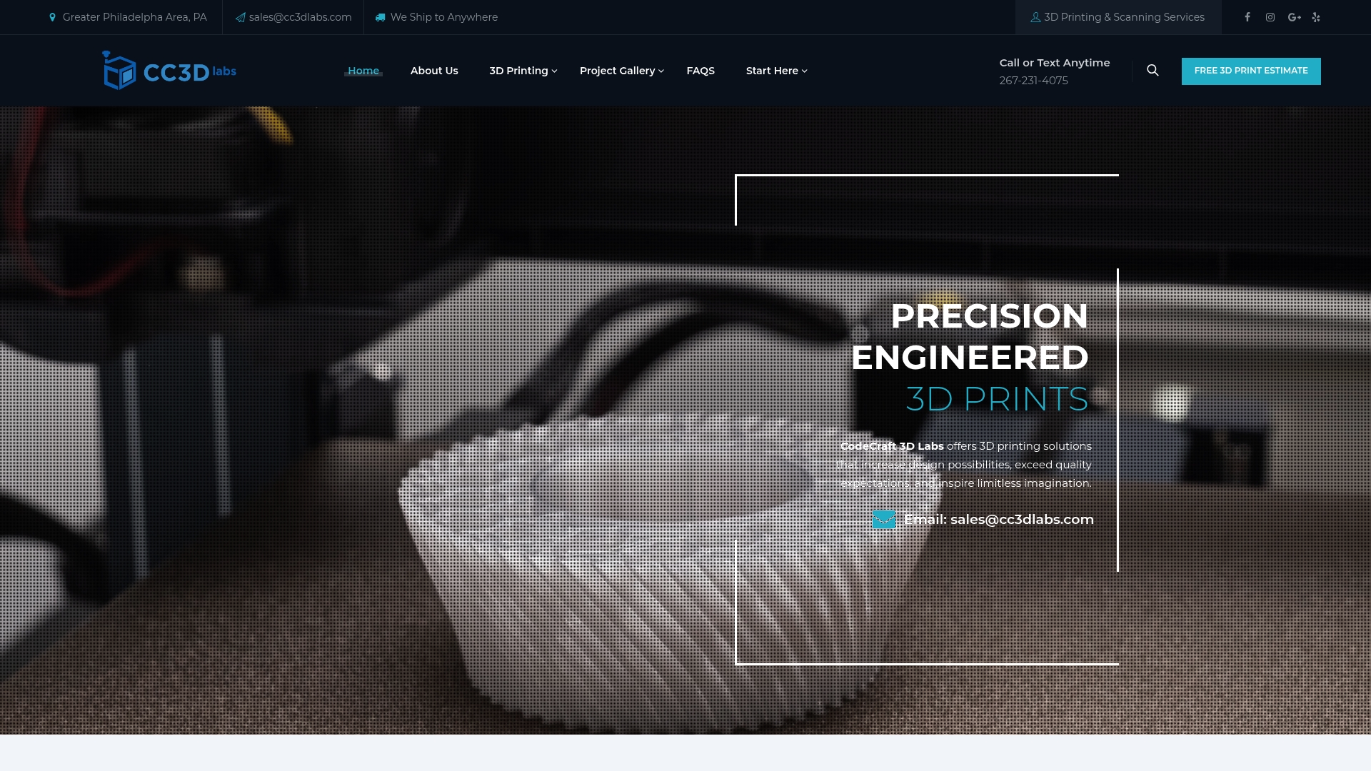
CC 3D Labs
At a Glance
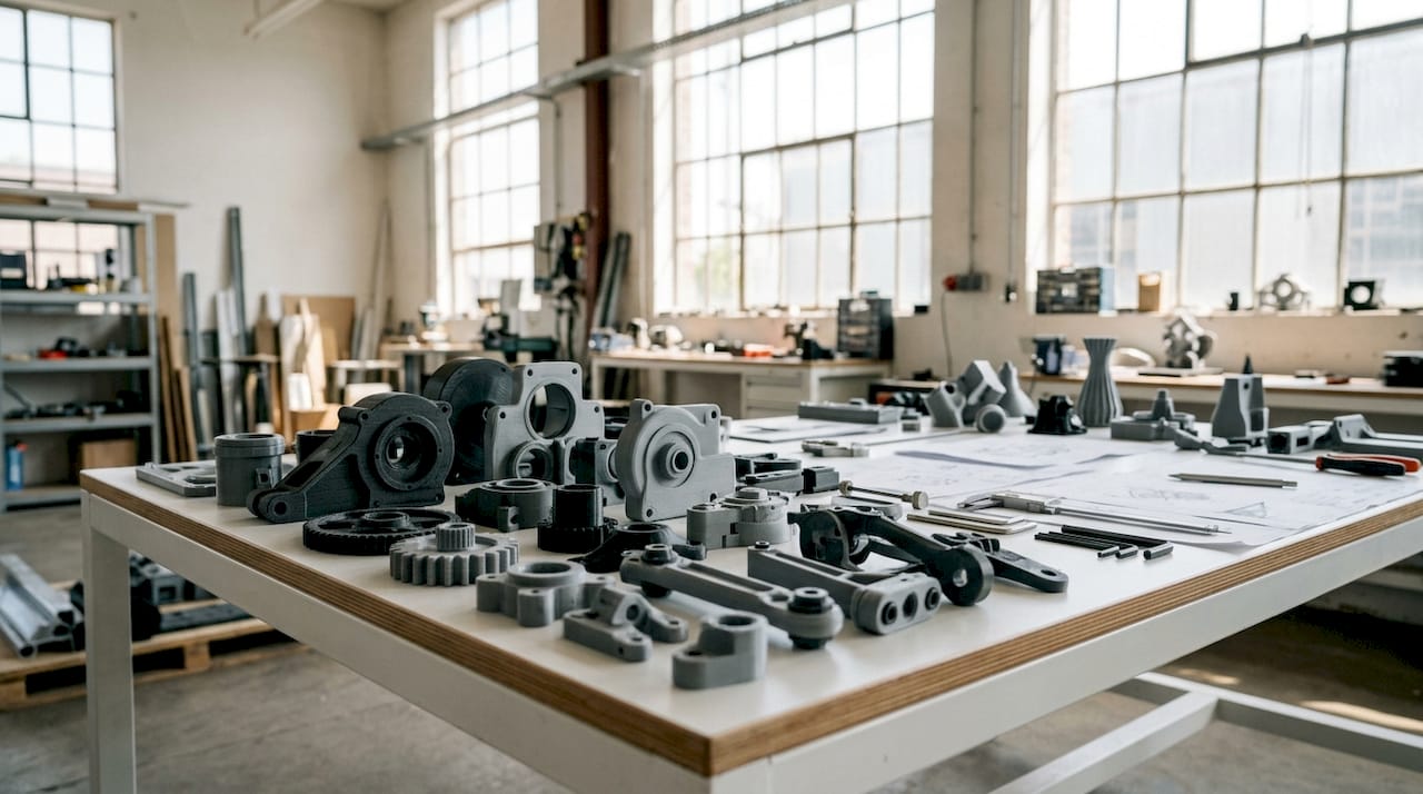
CC 3D Labs operates near Philadelphia and offers metrology-grade 3D scanning alongside filament-based printing. The shop focuses on functional parts, prototypes, and short-run manufacturing with options for multi-color and multi-material prints. The vendor advertises fast turnaround and local pickup plus nationwide shipping.
Core Features
CC 3D Labs combines on-demand FDM printing with CAD and 3D modeling services to support prototypes through batch production. The service lists a wide material selection that includes flexible and conductive filaments and engineering-grade options for load bearing parts. They also provide 3D scanning and repair support for reverse engineering and maintenance parts.
Key Differentiator
Local direct support paired with a broad filament catalog and precise printing for functional use cases. That mix targets product developers who need quick iterations, hands-on design feedback, and materials that perform in real applications.
Pros
Customer reviews report high-quality prints with strong dimensional accuracy, which supports use for functional components and test-fit prototypes. The shop offers multi-material and multi-color builds combined with engineering-grade filaments, making parts suitable for real-world loads. Local pickup and direct communication reduce lead time for nearby teams, while shipping covers national orders. Design support and CAD services help when files need repair or modification before print.
Cons
- Limited to FDM printing, so surface finish and ultra-fine detail achievable with resin or SLS are not available here.
Who It’s For
Small to medium manufacturers, product developers, mechanical engineers, and hobbyists who need durable, functional parts quickly. Local Philadelphia firms will benefit most from pickup and hands-on support, while teams nationwide can use shipping and file work.
Unique Value Proposition
The company emphasizes metrology-grade scanning plus hands-on local support. That combination shortens the loop between scanning, CAD fixes, and final prints, reducing iteration friction for parts that must meet tight fit and tolerance requirements.
Real World Use Case
A Philadelphia aerospace supplier used CC 3D Labs to scan a worn bracket, convert the scan into a repaired CAD model, and print a batch of engineering-grade replacement parts. The workflow kept tolerances tight and delivered parts suitable for assembly testing within the same week.
Pricing
Pricing varies by material, complexity, and volume and no fixed rates are posted. Reviews indicate the shop charges competitive rates. For an accurate figure you must request an online estimate or a quote for your specific project.
Website: https://cc3dlabs.com
American Additive Manufacturing
At a Glance
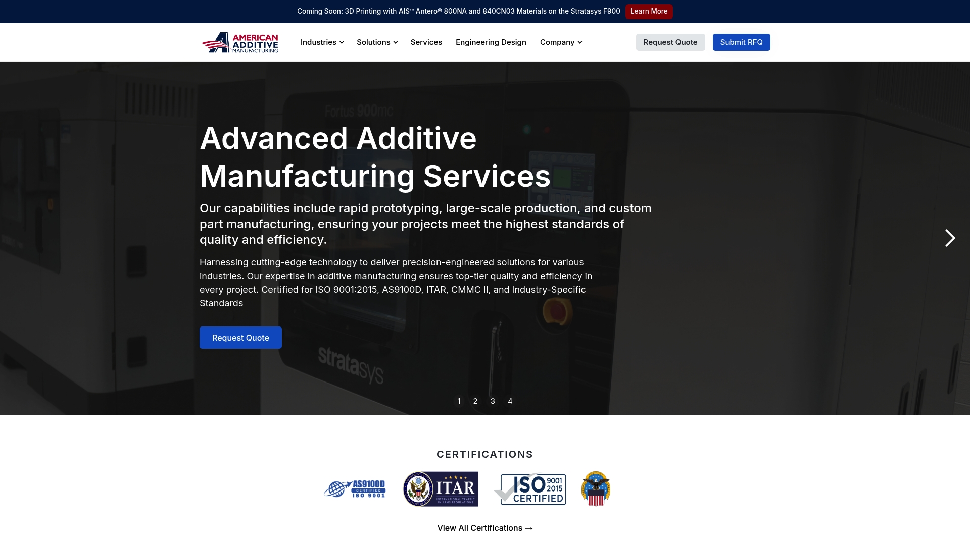
American Additive Manufacturing’s marketing materials state certification for ISO 9001:2015, AS9100D, ITAR, and CMMC II. Those standards target regulated industries such as aerospace, defense, medical, and automotive. The company pairs certified production with material testing and engineering support for prototype and short run parts.
Core Features
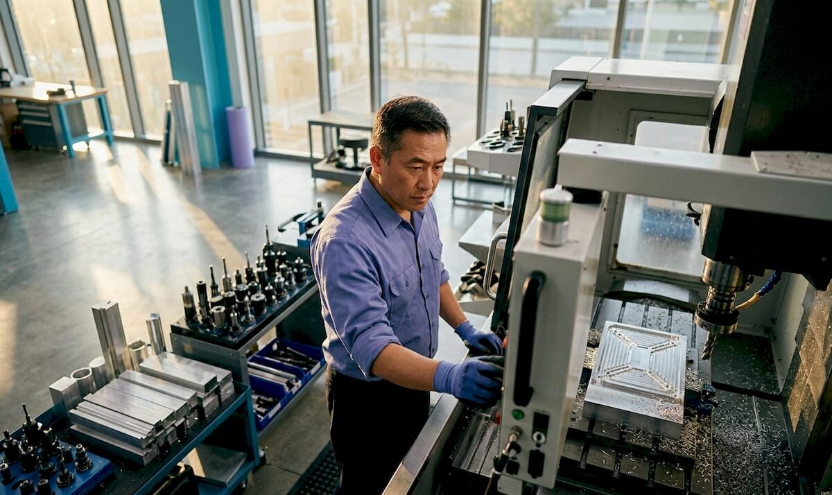
American Additive handles rapid prototyping, serial production, and advanced additive technologies across multiple polymer and resin systems. Material development and testing sit alongside reverse engineering and CAD services to shorten iteration cycles for engineers. Design and engineering support helps move parts from concept through qualification.
Key Differentiator
Those certifications combine with an in-house engineering team focused on industry-specific requirements for traceability and documentation. That combination makes the supplier suitable for programs that demand process control and material qualification. The vendor emphasizes meeting regulated program controls rather than commodity prototyping.
Pros
Certified processes and documented controls help teams qualify parts for regulated programs while keeping a clear audit trail. A wide materials set plus dedicated material testing and design for additive services helps you validate parts before small batch production. Reported work with notable clients indicates the company can support complex, compliance heavy contracts.
Cons
- Limited public detail on proprietary processes or unique technology. That lack of transparency makes direct technical comparisons harder.
- No clear pricing published. Quotes appear tailored and project based, so budgeting requires a consultation.
- Certifications and compliance add cost and administrative steps that may raise lead time for simple parts.
- Low online automation and no instant quoting mean you will likely need phone or email consultation for a scoped proposal.
When It May Not Fit
If you need an online configurator or same day automated quotes, this supplier may not fit. Their workflows look consultation driven and require scoped reviews. For rapid price shopping across suppliers expect slower response cycles.
Who It’s For
Manufacturers, engineers, and product designers who require certified, traceable additive manufacturing will find the fit best. Teams working on aerospace, defense, medical, or automotive programs benefit from documented processes. Small prototype shops focused solely on low cost consumer parts may find the model heavier than needed.
Real World Use Case
An aerospace OEM partnered with American Additive to produce interior aircraft components using certified FDM and SLA materials. That work reduced lead time for nonstructural assemblies while preserving traceability for qualification. Engineering support handled reverse engineering, fit checks, and transition into short run production.
Pricing
Pricing is not published online. Costing appears project based and typically requires design review and material testing input. Contact the vendor for a scoped proposal and timeline for budget planning.
Website: https://americanadditive.com
Shapeways
At a Glance
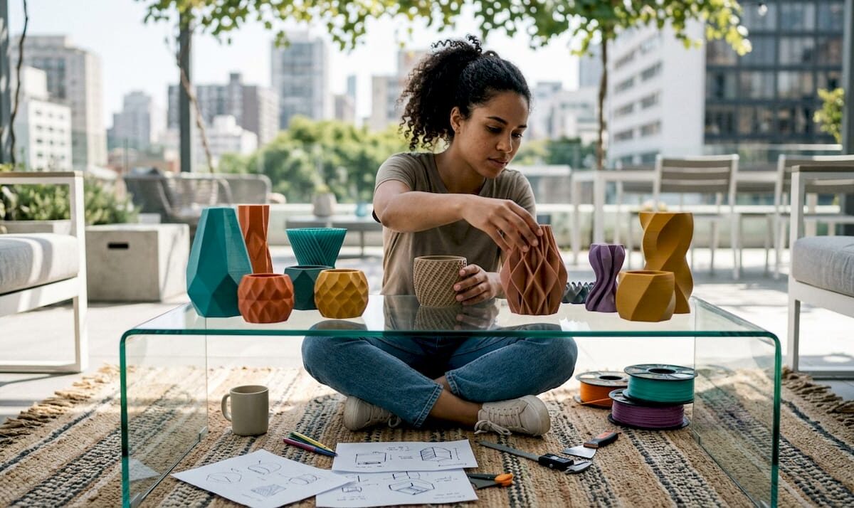
Shapeways’ marketing materials state it supports production runs from 1 to over 10,000 parts with no MOQs. That scale and flexibility make it usable for one-off prototypes and short production runs. The service also lists over 90 materials, covering common plastics and several metals.
Core Features
Shapeways combines a wide material catalog with multiple manufacturing methods, including additive manufacturing, CNC machining, and injection molding. It offers DFM feedback and professional design services to reduce iteration cycles and catch tolerance issues early. API links connect storefronts like Shopify and Etsy for direct fulfillment.
Key Differentiator
The standout detail is that scale claim and the vendor’s support across manufacturing methods. That scale pairs with centralized fulfillment and expert design advice. For teams that need to move from prototype to small production with one supplier, this alignment reduces vendor handoffs.
Pros
Material variety and finish options let you match functional requirements and surface appearance without switching suppliers. The global fulfillment network helps reduce shipping complexity for international orders and supports both single units and larger batches. Professional DFM feedback and design services help teams refine parts for manufacturability and assembly. The flexible technology mix supports prototypes, functional testing, and low-volume production, and the no-MOQs claim makes single-part orders possible.
Cons
- Pricing details are quote-based and not published, which adds friction for tight prototype budgets.
- The large set of material choices can overwhelm teams lacking materials expertise.
- Public information about the user interface and ordering workflow is limited.
- Lead times vary by material and process, so schedules may shift depending on chosen methods.
When It May Not Fit
If you need fixed, transparent pricing for immediate budget planning, a quote-only model will slow procurement. Teams without technical material knowledge will spend time learning options or paying for consulting. If guaranteed short lead times for a specific process are mandatory, variable production scheduling may not meet your deadlines.
Who It’s For
Product designers and startups that plan frequent iterations and need access to multiple processes will find value here. Small to medium enterprises that want to scale from prototype to small production with one supplier will benefit from the fulfillment and design services. If you handle small, casual hobby runs on a strict shoestring budget, this offering may feel heavyweight.
Real World Use Case
A startup building custom drone components uses selective laser sintering through Shapeways to produce prototype housings and functional test parts. The team iterates fit and tolerances with DFM feedback, then places low-volume production runs while keeping the same manufacturing partner.
Website: https://shapeways.com
Comparison of alternatives
Selecting a 3D printing vendor involves balancing material availability, supported processes, and compliance specifications to align with your project demands. Here we explore the offerings from CC 3D Labs, American Additive Manufacturing, and Shapeways to highlight their unique advantages and tradeoffs.
Material variety and process coverage
Shapeways supports an expansive set of over 90 materials and employs multiple manufacturing technologies, including SLS and metal printing. This extensive catalog accommodates a wide range of build requirements effectively. Meanwhile, CC 3D Labs specializes in engineering-grade filaments and multi-material FDM processes. While limited compared to Shapeways in material diversity, CC 3D Labs excels in creating load-bearing, functional prototypes and small production batches.
Compliance to aerospace and regulated standards
American Additive Manufacturing stands out for its certifications like AS9100D, making it a strong choice for aerospace, defense, and medical applications where traceability and documentation are crucial. Their processes align tightly with regulated product standards, though this compliance adds potential time and cost tradeoffs unsuitable for projects emphasizing speed or simplicity.
Best fit
- Engineers and design firms in Philadelphia needing reliable local services for functional prototypes will find CC 3D Labs compelling. Their emphasis on material quality and personalized CAD feedback delivers precise results.
- Teams working under rigorous program controls, such as those in the aerospace or medical sectors, should consider American Additive Manufacturing for its strong compliance and process transparency.
- Product developers and fashion professionals planning frequent iterations or scaling production across multiple methods will appreciate Shapeways for its material diversity and batch flexibility.
Our pick
CC 3D Labs excels for users in Philadelphia seeking precision scanning and rapid, durable prototyping guidance locally. Their hands-on approach and engineering-grade processes address functional needs directly. While Shapeways provides extensive scalability and material diversity, this localized precision sets CC 3D Labs apart for regional, fit-critical projects.
In selecting alternatives for custom 3D printing services, important factors include material range, functional printing capabilities, and production scale.
| Product | Core Feature | Key Differentiator | Best For | Pricing | Notable Limitation |
|---|---|---|---|---|---|
| CC 3D Labs | FDM printing and 3D scanning | Local direct support for user feedback | Small to medium manufacturers and product developers | Price not published | Limited to FDM technology |
| American Additive Manufacturing | Certified production processes | Industry certifications | Manufacturers in aerospace, defense, medical industries | Price not published | Requires consultation for quotes and project specifications |
| Shapeways | Wide range of materials and methods | No minimum order quantities | Product designers scaling from prototype to small production | Price not published | Quotes only, variable production scheduling |
How to Choose the Right cd3dcreations.com Alternatives for Durable, Accurate 3D Printing
The search for reliable cd3dcreations.com alternatives often centers on fast turnaround and functional parts with precise details. Product developers, mechanical engineers, and small to medium manufacturers need a trusted partner who can handle multi-color and engineering-grade filament prints while providing design support and metrology-grade scanning.
Cc3dlabs delivers on these needs with custom filament-based 3D printing and 3D scanning solutions near Philadelphia. Whether you require quick prototype iterations or batch production with local pickup or shipping, Cc3dlabs ensures durable parts and CAD modeling support to reduce errors before printing. Explore Cc3dlabs’ offerings to secure accurate, reliable manufacturing for your projects.
Learn more about Cc3dlabs services and request your free online estimate today to move from design to finished part with confidence.
FAQ
How does Cc3dlabs support on-demand 3D printing needs?
Cc3dlabs provides on-demand FDM printing with a wide material selection. Their focus on functional parts, prototypes, and short-run manufacturing allows for fast turnaround times tailored for product developers and engineers. Teams needing quick iterations can expect reliable, high-quality prints suited to real applications.
What is the difference between Cc3dlabs and American Additive Manufacturing?
American Additive Manufacturing emphasizes its industry certifications like ISO 9001:2015 and AS9100D, which support regulated sectors such as aerospace and defense. Cc3dlabs offers a strong local support model with fast turnaround for functional prototypes, making it more suitable for teams seeking immediate, hands-on assistance without extensive compliance requirements.
Can I use Cc3dlabs for multi-material 3D printing?
Cc3dlabs offers multi-material and multi-color printing options using various engineering-grade filaments. This enables creators to produce parts that meet specific functional demands while ensuring that design modifications can be made efficiently.
What should I consider if I need a wide material catalog?
If a wide material catalog is essential, Shapeways excels with over 90 available materials including plastics and metals. Cc3dlabs, while offering a strong filament selection, focuses primarily on functional filaments and may not cover as broad a range. Evaluating specific material needs will help you choose the best fit.
How does Cc3dlabs ensure dimensional accuracy in prints?
Cc3dlabs is known for delivering high-quality prints with strong dimensional accuracy. This quality makes their services ideal for functional components and test-fit prototypes, giving clients confidence in the integrity of their parts during assembly testing.