TL;DR:
- Scan to CAD transforms raw 3D scan data into editable, parametric models for manufacturing and design purposes. The process involves scanning, data export, alignment, feature extraction, and exporting the final CAD file, with reconstruction being the most time-consuming step. Advanced tools and AI-assisted software help streamline the workflow, but operator skill remains essential for accuracy and usability.
Scan to CAD is the process of converting raw 3D scan data into editable, parametric CAD files used for design, manufacturing, and prototyping. Formally called reverse engineering from scan data, this workflow transforms millions of captured spatial points into structured models in formats like STEP, SLDPRT, or OBJ. Tools like Geomagic, Autodesk Fusion 360, and Creaform Metrology Suite sit at the center of this process. Whether you are recreating a broken part, building a custom fixture, or digitizing a physical object for redesign, scan to CAD gives you a precise, modifiable starting point that raw scan files simply cannot provide.
What is the scan-to-CAD workflow, step by step?
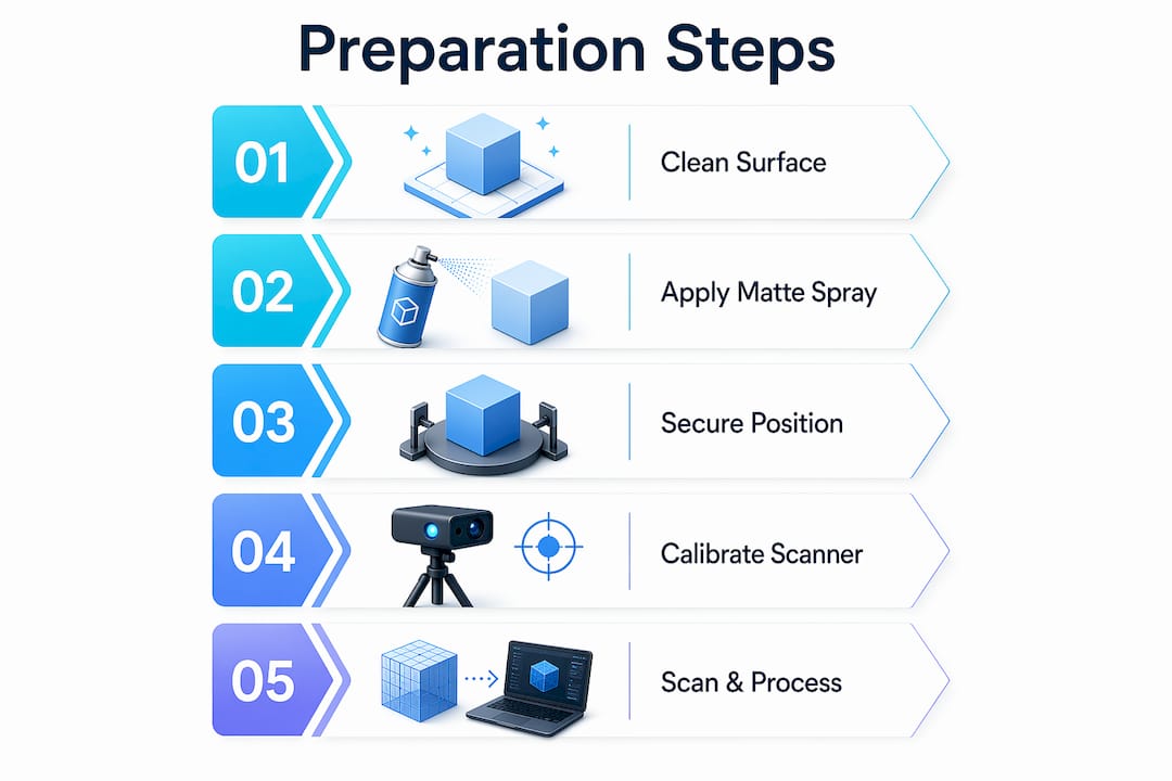
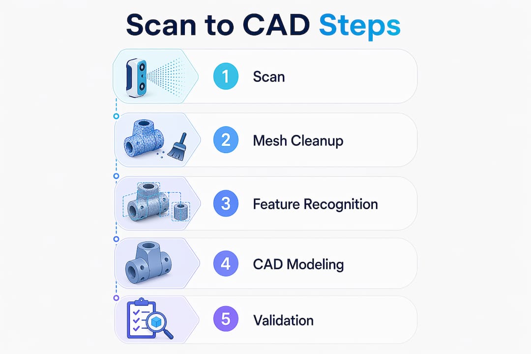
The scan-to-CAD process follows a five-step lifecycle: scanning, data export and import, alignment, feature extraction, and exporting parametric files. Each stage builds on the last, and skipping any one of them produces unreliable results downstream.
-
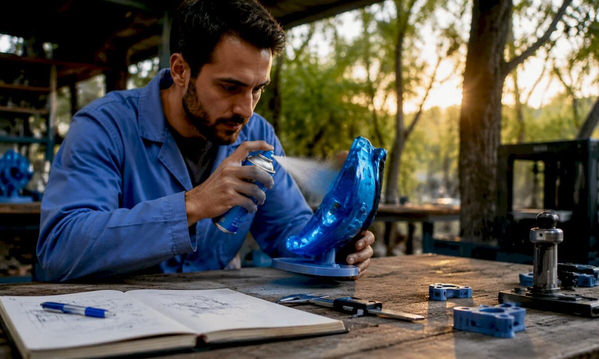
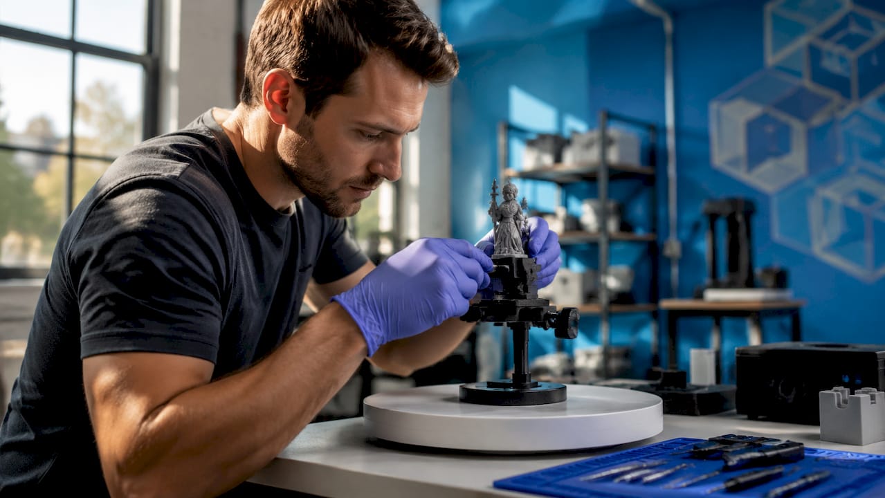
Capture the object with a 3D scanner. Structured light scanners, laser scanners, and photogrammetry rigs all capture surface geometry as a point cloud. The output is a dense collection of XYZ coordinates that represents the physical object’s shape.
-
Export the scan in a compatible file format. OBJ files carry color and texture, STL files carry geometry only, and STEP files carry parametric engineering data. Choosing the right format at this stage saves significant rework later. STL works for geometry checks; STEP is the target for fully editable engineering models.
-
Import and align the mesh in CAD software. Once inside a tool like Autodesk Fusion 360 or Autodesk ReCap, the mesh must be oriented correctly. Misalignment in this step causes design errors that compound through every subsequent modeling decision.
-
Extract features and reconstruct geometry. This is the most demanding step. You identify planes, cylinders, fillets, and other geometric primitives in the mesh, then model them as parametric features. Auto-surfacing the raw mesh almost always creates unmanageable files. Fitting primitives to the mesh produces clean, editable CAD geometry.
-
Export the finished parametric model. The final output is a native CAD file, typically STEP or a format like SolidWorks SLDPRT, ready for modification, simulation, or direct manufacturing.
Pro Tip: A basic scan-to-CAD project can be completed in roughly 24 hours with the right hardware and software combination. Plan your scanning session carefully so you spend that time on modeling, not on fixing scan data.
Which tools are used for scan to CAD in 2026?

The scan-to-CAD software and hardware market has matured significantly. The right combination depends on your accuracy requirements, budget, and the complexity of the part you are working with.
Professional-grade scanners:
- Creaform HandySCAN and the Creaform Metrology Suite handle high-accuracy industrial scanning and include a dedicated Scan-to-CAD module that automates several post-processing steps.
- Artec 3D scanners, including the Artec Eva and Artec Leo, are widely used for medium-complexity parts and organic shapes.
Mobile and accessible options:
- iPhones and iPads equipped with LiDAR sensors (iPhone 12 Pro and later) provide a low-cost entry point for less demanding projects. Apps like Polycam export directly to formats compatible with Fusion 360.
- AI-assisted tools reduce turnaround times by automating manual stages like point-cloud tracing, making mobile LiDAR a practical option for concept work and reference modeling.
CAD and post-processing software:
- Autodesk Fusion 360 supports importing meshes and converting them using prismatic or faceted approaches, with built-in mesh simplification tools.
- Geomagic Design X specializes in reverse engineering and offers semi-automated feature extraction directly from scan data.
- Scan2CAD converts raster images and PDFs into CAD formats and is widely used for professional-grade CAD and CNC conversion on both Windows and macOS.
The trend in 2026 is toward AI-assisted mesh cleanup and feature recognition. These tools do not replace engineering judgment, but they cut the time spent on repetitive cleanup tasks by a meaningful margin. For complex organic shapes, Geomagic still leads. For prismatic mechanical parts, Fusion 360 with a clean STL import is often the fastest path.
What challenges do users face when converting scan data to CAD?
The biggest misconception in scan to CAD is treating the scan data as a finished model. A 3D scan is a visual reference blueprint. It shows you what the object looks like, not how it was designed. Getting an editable CAD model requires reconstruction, not conversion.
“A 3D scan is only a visual reference blueprint; manual reconstruction is needed to get an editable CAD model.” — Einstar Reverse Engineering Guide
Auto-surfacing raw scan meshes often leads to unmanageable files with thousands of irregular faces. The correct approach is to use the mesh as a dimensional reference and fit parametric features, like cylinders, planes, and fillets, on top of it. This takes more time but produces a model you can actually modify.
Mesh cleanup and alignment are the other major friction points. Dirty meshes with holes, noise, or overlapping faces cause feature extraction to fail or produce inaccurate geometry. Tools like Autodesk ReCap help orient and clean scans before they enter the CAD environment, but mesh cleanup and point cloud alignment still require operator attention and judgment.
The post-scan processing phase consistently takes more time than the scanning itself. Experienced practitioners budget two to four times as much time for reconstruction as for data capture. If you are new to the CAD modeling workflow, that ratio is often surprising and worth planning for from the start.
Pro Tip: Not every scan needs to become a fully parametric solid model. For fit-check or reference work, using the scan mesh as an overlay inside Fusion 360 is faster and often sufficient. Match your modeling effort to the actual project goal.
How is scan to CAD applied in real prototyping and design workflows?
Scan to CAD has three primary applications in practical design and manufacturing work: reverse engineering broken or legacy parts, creating custom fixtures and enclosures, and accelerating product iteration.
Reverse engineering broken or legacy parts
When a part breaks and no drawing exists, a 3D scan gives you the geometry you need to recreate it. Editable scan-to-CAD files enable modifications like thickening ribs, adjusting tolerances, or changing materials before the part goes back into production. This is far faster than measuring by hand and rebuilding from scratch.
Custom fixture and enclosure design
Designers scan an existing assembly or environment, then model a new part directly around the scan data. A custom bracket, housing, or adapter can be designed to fit perfectly because the scan captures the actual geometry of the mating surfaces, not a nominal drawing that may not reflect real-world tolerances.
Accelerating product iteration with 3D printing
The combination of scan to CAD and 3D printing creates a tight iteration loop. You scan a physical prototype, modify the CAD model, print a revised version, and test it. Each cycle takes hours instead of days. This workflow is especially effective for ergonomic parts, consumer products, and any design where fit and feel matter as much as function.
| Application | Primary benefit | Typical output format |
|---|---|---|
| Reverse engineering legacy parts | Recreate geometry without original drawings | STEP, SLDPRT |
| Custom fixture design | Fit new parts to existing assemblies | STEP, STL for printing |
| Product iteration with 3D printing | Rapid physical testing of design changes | STL for FDM or SLA printing |
| Digital asset creation | Preserve physical objects as editable models | OBJ, STEP |
The 3D modeling process for businesses follows a similar logic: scan data provides the dimensional foundation, and CAD modeling adds the engineering intent. The two together produce results that neither can achieve alone.
Key takeaways
Scan to CAD converts physical objects into editable parametric models by combining accurate scan data with deliberate CAD reconstruction, and the quality of the output depends entirely on the operator’s modeling skill and process discipline.
| Point | Details |
|---|---|
| Scan data is a blueprint, not a model | Raw scans require manual reconstruction to become editable CAD geometry. |
| Five-step workflow | Scanning, export, alignment, feature extraction, and parametric export define every successful project. |
| Tool selection matters | Geomagic Design X leads for organic shapes; Fusion 360 works well for prismatic mechanical parts. |
| Post-processing takes the most time | Budget two to four times more time for reconstruction than for the scan itself. |
| Match effort to project goals | Reference overlays in Fusion 360 can replace full solid modeling when fit-check is the only requirement. |
Why scan to CAD is harder than it looks, and worth it anyway
I have seen a lot of people come into scan-to-CAD projects expecting the software to do the heavy lifting. They scan an object, import the mesh, hit a button, and expect a clean parametric model to appear. That is not how it works, and that gap between expectation and reality is where most projects stall.
The value of scan data is tied entirely to the operator’s ability to interpret and reconstruct design intent accurately. A mesh tells you where the surface is. It does not tell you whether that surface is supposed to be a 25mm cylinder or a 24.97mm cylinder with manufacturing variation. That judgment call is yours, and it requires both CAD skill and domain knowledge about the part you are modeling.
What I find genuinely exciting about the current state of the tools is that AI-assisted feature recognition in software like Geomagic Design X is starting to close that gap. It does not eliminate the need for engineering judgment, but it handles the tedious parts of mesh cleanup and primitive fitting faster than any manual workflow. For someone learning the process, that means you can focus your attention on the decisions that actually matter.
My honest recommendation: start with a simple prismatic part, something with flat faces, clear holes, and obvious geometry. Get that workflow clean before you attempt organic shapes or complex assemblies. The skills transfer directly, and you will build confidence in the process before the difficulty ramps up.
— Justin
Take your scan-to-CAD projects further with Cc3dlabs
If you are working on a project that requires precise scan data or professional CAD modeling support, Cc3dlabs offers metrology-grade 3D scanning and full CAD modeling services from its facility near Philadelphia. Whether you need a single part scanned and reconstructed or a full reverse engineering workflow for a production component, the team brings the equipment and expertise to deliver accurate, print-ready files.

From scan capture through to on-demand 3D printing of the finished model, Cc3dlabs handles the complete workflow. Local pickup is available, and shipping options cover clients across the United States and internationally. Request a free online estimate directly from the website to get started.
FAQ
What is scan to CAD in simple terms?
Scan to CAD is the process of taking a 3D scan of a physical object and converting that scan data into an editable CAD model. The result is a parametric file you can modify, manufacture, or 3D print.
What file formats are used in the scan-to-CAD process?
OBJ is preferred for color and texture, STL for geometry-only 3D printing, and STEP for parametric engineering models. STEP is the standard output format for fully editable scan-to-CAD results.
How long does a scan-to-CAD project take?
A basic project can be completed in roughly 24 hours with the right hardware and software. More complex parts with organic geometry or tight tolerances require significantly more time, primarily in the reconstruction phase.
Is scan to CAD the same as reverse engineering?
Scan to CAD is the primary method used in reverse engineering, but reverse engineering is the broader discipline. Reverse engineering can also involve manual measurement, teardown analysis, and functional testing beyond what scan data alone provides.
What is the hardest part of the scan-to-CAD workflow?
Feature extraction and parametric reconstruction are consistently the most demanding steps. Auto-surfacing raw meshes produces messy, uneditable geometry. Fitting geometric primitives manually to the mesh takes skill but delivers clean, usable CAD models.