Engineer scanning mechanical part in lab

What Is Reverse Engineering 3D: A Practical Guide


TL;DR:

  • Reverse engineering 3D converts physical parts into parametric CAD models using scan-to-CAD workflows. It speeds up design, repair, and quality inspection by capturing complex geometries with 3D scanners. Restoring engineering intent ensures functional accuracy and manufacturability in industrial applications.

Reverse engineering 3D is defined as the process of capturing a physical object’s geometry and converting it into an editable, parametric CAD model for reproduction, redesign, or inspection. The industry standard term for this workflow is “scan-to-CAD,” and it relies on 3D scanning to collect surface data far faster than manual measurement ever could. Where traditional methods with calipers or coordinate measuring machines (CMMs) take days or weeks, scan-based reconstruction compresses that timeline to hours or days. Cc3dlabs applies this workflow daily for product developers, engineers, and designers who need production-ready digital models from physical parts.

What is the role of 3D scanning in reverse engineering?

3D scanning is the foundation of modern reverse engineering. Without it, capturing complex organic shapes or worn surfaces with enough accuracy for manufacturing is nearly impossible using hand tools alone.

Structured light 3D scanner projecting grid on object

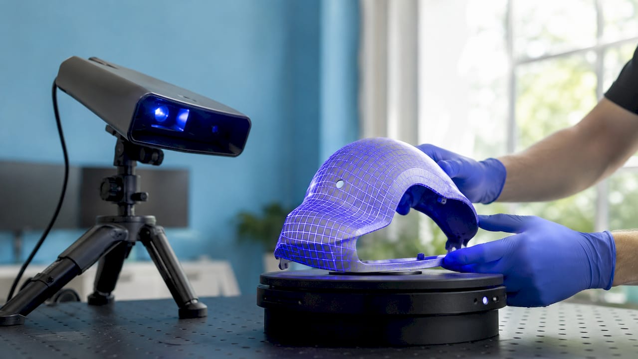
Two scanning technologies dominate professional workflows today. Structured light scanning projects a grid of light onto a surface and measures how it deforms to calculate geometry. Laser triangulation fires a laser line across the part and uses the reflection angle to build surface data. Both methods produce raw point clouds, which are dense collections of measured coordinates in three-dimensional space.

Standard scanning accuracy in professional settings falls between 50 and 100 microns (0.05–0.1 mm). That level of precision is sufficient for most industrial applications, from aerospace brackets to consumer product housings. Environmental factors like temperature shifts and vibration directly affect that precision, which is why controlled scanning environments matter.

Once the scanner collects enough data, the software stitches individual scans into a unified polygon mesh. A mesh is made of millions of small triangles that approximate the part’s surface. This mesh is not directly editable as a CAD model. It is a visual representation, not a parametric solid, and that distinction drives the next phase of the workflow.

  • Structured light scanning: Best for small to medium parts with fine surface detail
  • Laser triangulation: Effective for larger parts and industrial environments
  • Point cloud output: Raw coordinate data requiring cleanup before modeling
  • Polygon mesh: Processed surface geometry used as the reference for CAD reconstruction
  • CMM comparison: Contact-based CMMs measure discrete points; scanners capture millions simultaneously

Pro Tip: Apply a thin, uniform matte spray to shiny or translucent surfaces before scanning. Reflective surfaces scatter laser or structured light, creating gaps and noise in the point cloud that are difficult to fix in post-processing.

What is the standard workflow for reverse engineering in 3D?

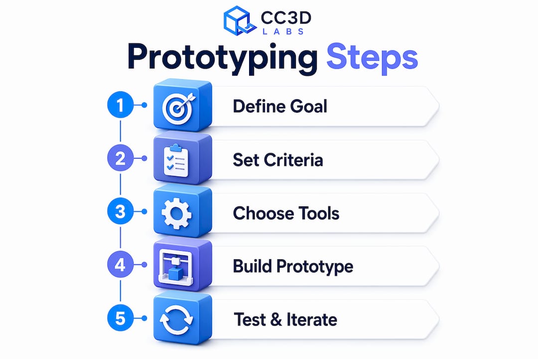
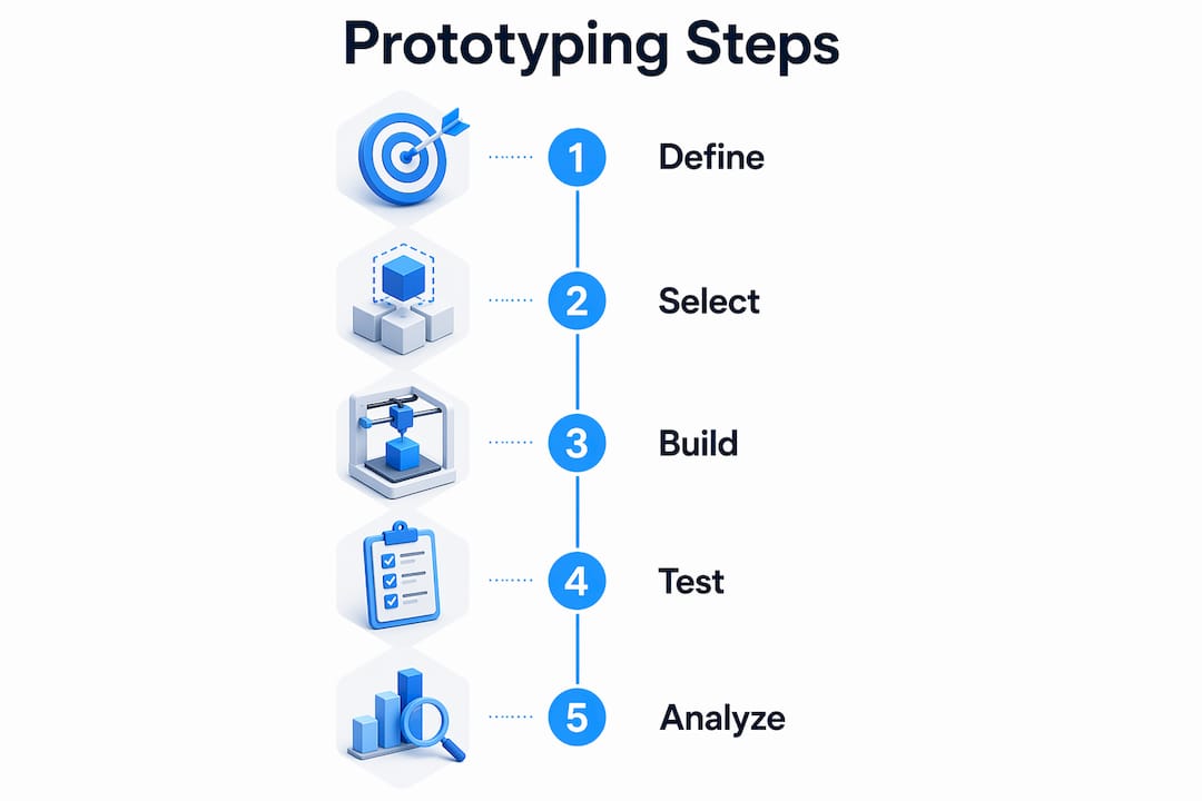
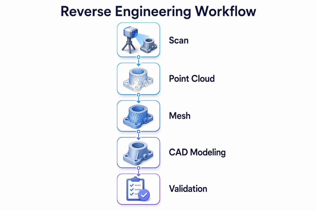
The reverse engineering workflow follows five sequential steps. Skipping any one of them increases the risk of producing a model that looks right but fails in manufacturing.

  1. Part evaluation and preparation. Examine the physical part for wear, damage, and surface condition. Identify which features are functional and which are artifacts of use. Clean and prep the surface for scanning.

  2. Data capture. Scan the part using structured light or laser triangulation. Capture multiple passes from different angles to cover all surfaces. Apply reference targets or markers if the part requires multi-position scanning.

  3. Point cloud and mesh processing. Import raw scan data into processing software. Align multiple scans, remove noise, fill small gaps, and generate a clean polygon mesh. This step determines the quality ceiling for everything that follows.

  4. CAD reconstruction. Use the mesh as a reference to rebuild the part as a parametric CAD model. Engineers fit geometric primitives, such as planes, cylinders, and fillets, to the mesh rather than simply wrapping it. This is where design intent is restored rather than copied.

  5. Validation. Compare the finished CAD model back to the original scan data using deviation mapping. Color-coded deviation maps highlight where the model diverges from the scan. Deviations exceeding application-specific thresholds must be corrected before the model goes to manufacturing.

“The real challenge lies in the scan-to-CAD step, where engineers rebuild clean parametric models from raw meshes for manufacturing suitability.” This is where expertise separates a functional part from a failed one.

The scan-to-CAD workflow compresses what once took weeks into a process measured in hours. That speed advantage directly reduces product development costs and accelerates time to market for manufacturers and product developers alike.

How does reverse engineering 3D restore engineering intent beyond shape copying?

Infographic showing reverse engineering 3D step workflow

Engineering intent is the set of functional decisions the original designer made: specific tolerances, geometric relationships, and feature dimensions that make a part work. Simply tracing the scanned mesh does not recover those decisions.

A worn shaft, for example, may measure 24.87 mm in diameter after years of use. The original design called for 25.00 mm. If you model what you measure, you reproduce the wear. If you recognize the intent, you model 25.00 mm and restore the part to its functional specification. Distinguishing intended geometry from surface wear is one of the most critical skills in the entire process.

Common mistakes engineers make when skipping this step include:

  • Replicating defects: Modeling cracks, dents, or wear as designed features
  • Ignoring tolerances: Producing nominal geometry without fit or clearance specifications
  • Over-trusting the mesh: Accepting scan noise as real geometry
  • Missing symmetry: Failing to apply mirror or pattern constraints that the original design used
  • Skipping feature recognition: Modeling freeform surfaces where the original used a simple cylinder or plane

Pro Tip: When reconstructing holes, always check whether the diameter corresponds to a standard drill size or thread specification. Parametric CAD modeling with standard feature dimensions makes downstream manufacturing far simpler than working from arbitrary measured values.

The balance between accuracy and simplification is deliberate. A model does not need to match the scan to within 5 microns everywhere. It needs to match within the tolerance that the application demands. Over-modeling wastes time and creates unnecessarily complex files. Under-modeling produces parts that do not fit. Experienced engineers know where each threshold sits.

What practical applications and industries benefit from reverse engineering 3D?

Reverse engineering 3D solves problems across a wide range of industries. The common thread is a physical object that needs a digital counterpart, whether for reproduction, modification, or quality verification.

  • Legacy part reproduction: Mining and energy companies regularly use reverse engineering to reproduce parts for equipment that manufacturers no longer support. When original drawings do not exist, scanning obsolete parts is the only path to a replacement.
  • Product redesign: Consumer product developers scan existing objects to understand their geometry, then modify the CAD model to improve ergonomics, reduce weight, or adapt for new manufacturing methods.
  • Quality inspection: Deviation analysis compares manufactured parts to their CAD reference. This application uses the same scanning technology in reverse: the CAD model is the standard, and the scan reveals how closely production parts match it.
  • 3D printing and CNC workflows: Reverse engineered CAD models feed directly into 3D printing services and CNC machining programs. The model must be parametric and clean for toolpaths to generate correctly.
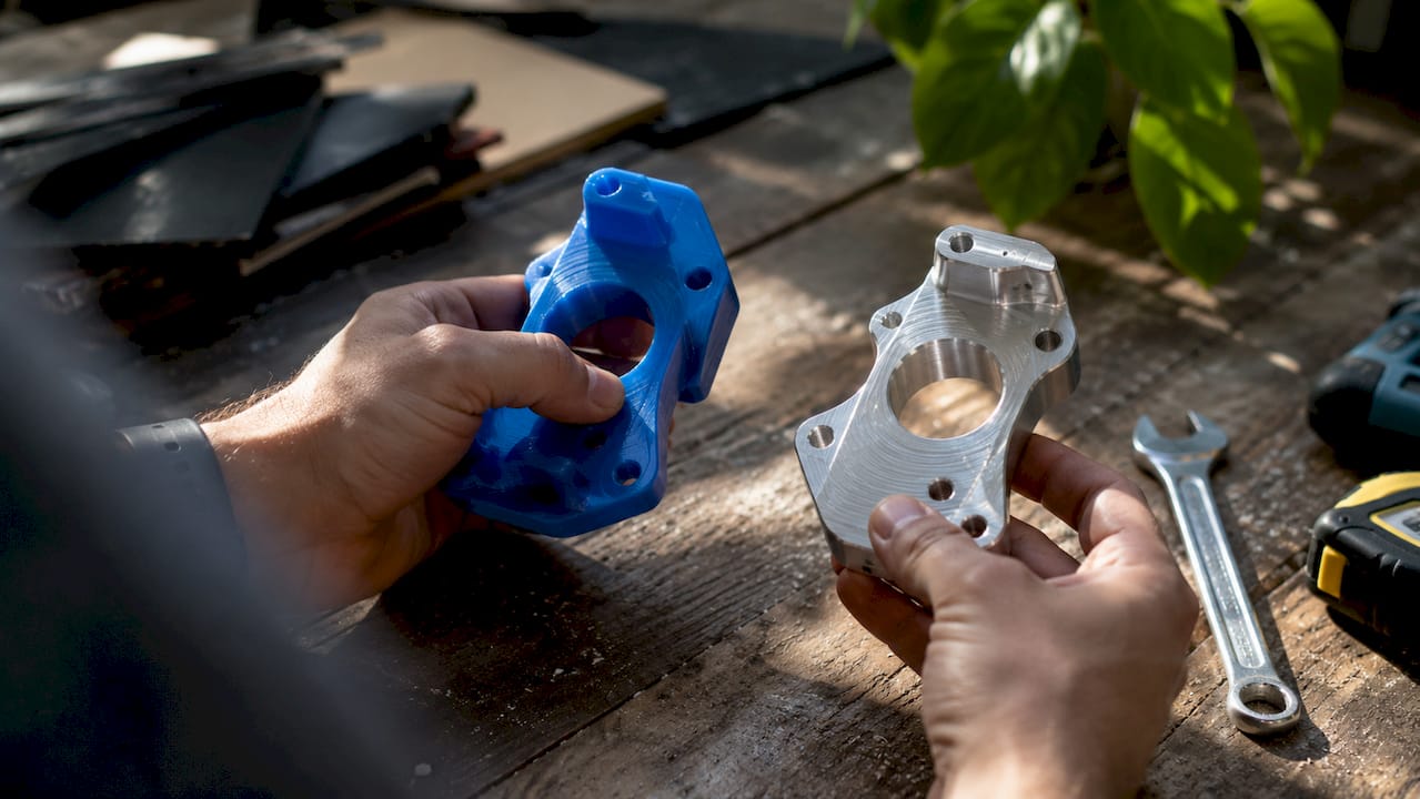
  • Prototyping acceleration: Designers scan a hand-built foam or clay model, convert it to CAD, and send it to production within the same day. That speed is not achievable with manual measurement.

The scan-to-CAD process also supports injection molding workflows, where precise wall thickness and draft angles must be modeled explicitly. A mesh alone cannot drive a mold design. A parametric CAD model can.

What are common challenges and tips for successful 3D reverse engineering projects?

Every reverse engineering project encounters friction. Knowing where the friction comes from lets you address it before it costs time or accuracy.

Surface condition is the most common source of scan failure. Shiny metals, clear plastics, and very dark surfaces all interfere with optical scanners. Matte sprays solve this for most materials, but the coating must be thin and uniform. Thick or uneven coatings add measurable geometry to the surface and skew results.

Environmental control matters more than most beginners expect. Temperature fluctuations and vibration introduce measurement error that accumulates across a multi-scan session. Professional scanning environments use stable lighting, controlled temperature, and vibration-isolated tables for critical work.

  • Mesh cleanup: Remove floating points, fill holes, and smooth noise before starting CAD reconstruction. A poor mesh produces a poor model regardless of how skilled the engineer is.
  • Feature recognition software: Tools that automatically detect planes, cylinders, and spheres in the mesh speed up reconstruction and reduce human error.
  • Deviation thresholds: Set acceptable deviation limits before modeling, not after. Application-specific tolerances for aerospace differ from those for consumer goods.
  • Expert review: Have a second engineer review the CAD model against the scan before releasing it to manufacturing. Deviation mapping catches errors that visual inspection misses.

Pro Tip: Break complex parts into logical sub-regions during reconstruction. Model each functional zone separately, then assemble them. This approach makes it easier to identify where the model drifts from the scan and correct it without rebuilding the entire file.

Key Takeaways

Reverse engineering 3D converts physical parts into parametric CAD models through a five-step scan-to-CAD workflow that restores engineering intent, not just geometry, making parts manufacturable and functionally accurate.

Point Details
Scanning replaces manual measurement 3D scanners collect millions of data points in hours, replacing days of caliper and CMM work.
Mesh is not a CAD model Raw scan output requires parametric reconstruction before it can drive CNC, molding, or printing.
Engineering intent must be restored Model the original design specification, not the worn or defective scanned shape.
Validation is non-negotiable Deviation mapping confirms the CAD model matches the scan within manufacturing tolerances.
Applications span every industry From legacy part reproduction to quality inspection, reverse engineering serves manufacturing, design, and prototyping.

Why engineering intent is the real deliverable in reverse engineering

Most articles about reverse engineering focus on the scanning hardware. That is the wrong place to put the emphasis. The scanner is just a measuring tool. The real work happens when an engineer sits down with a mesh and decides what the original designer intended.

I have seen projects where teams invested in high-end scanning equipment and still delivered unusable models. The scans were beautiful. The mesh was clean. But the CAD reconstruction copied the worn geometry faithfully, including a shaft that was 0.3 mm undersize from years of friction wear. The replacement parts failed immediately because the engineer modeled what existed rather than what was designed.

The scan-to-CAD step is where engineering judgment is irreplaceable. Software can detect that a surface is approximately cylindrical. Only an engineer can decide whether that cylinder should be 25.00 mm or 24.87 mm based on context, fit requirements, and standard sizing conventions. Technology accelerates the data collection. It does not make that call for you.

My advice to product developers and engineers entering this field: invest as much time learning CAD reconstruction and feature recognition as you do learning to operate the scanner. The 3D modeling process is where value is created. The scan is just the starting point. And always run deviation analysis before you sign off. A color map that looks green across the board is the only honest confirmation that your model is ready for production.

— Justin

Cc3dlabs scanning and CAD services for your reverse engineering needs

Cc3dlabs offers professional 3D scanning and CAD modeling near Philadelphia, with capabilities that cover the full reverse engineering workflow from initial scan to validated parametric model.

https://cc3dlabs.com

The team at Cc3dlabs works with product developers, engineers, and manufacturers who need accurate digital models from physical parts. Services include metrology-grade scanning, mesh processing, parametric CAD reconstruction, and deviation analysis. Whether you need a single legacy part reproduced or a batch of components digitized for redesign, Cc3dlabs delivers models built for manufacturing, not just visualization. Request a free online estimate to get your project scoped quickly.

FAQ

What is reverse engineering 3D in simple terms?

Reverse engineering 3D is the process of scanning a physical object and converting the scan data into an editable CAD model. The goal is a parametric digital file that can be used for manufacturing, redesign, or inspection.

How accurate is 3D scanning for reverse engineering?

Professional 3D scanners typically achieve accuracy between 50 and 100 microns (0.05–0.1 mm). Environmental factors like temperature and vibration affect that precision, so controlled scanning conditions are standard practice for industrial work.

What is the difference between a scan mesh and a CAD model?

A scan mesh is a surface made of millions of triangles that represents the object’s shape but cannot be directly edited or used to drive manufacturing. A parametric CAD model contains geometric features with defined dimensions and relationships, making it suitable for CNC machining, 3D printing, and injection molding.

Why does validation matter in a reverse engineering workflow?

Validation compares the finished CAD model to the original scan using deviation mapping. Color-coded maps reveal where the model diverges from the measured part, allowing engineers to correct errors before manufacturing begins and avoid producing faulty parts.

What industries use reverse engineering 3D most often?

Manufacturing, energy, mining, consumer product development, and aerospace all rely on reverse engineering to reproduce obsolete parts, inspect production quality, and accelerate product redesign. Any industry that works with physical parts and needs digital models benefits from the process.

Engineer assembling prototype at workbench

The Role of Prototypes in Product Development


TL;DR:

  • Prototypes turn abstract ideas into testable models to reduce costly mistakes during product development. Using multiple rapid iterations and appropriate fidelity levels accelerates timelines, cuts rework costs, and improves stakeholder alignment. Modern 3D printing enables fast, affordable physical prototypes, supporting better design decisions and faster market entry.

A prototype is a testable, tangible model built before full-scale production begins. The role of prototypes in product development is to transform abstract ideas into physical or digital objects that can be tested, challenged, and refined. Companies that skip this step pay for it later. Prototyping tools like Figma for digital products and 3D printing for physical goods give product developers a concrete way to validate assumptions before they become expensive mistakes. The data is clear: companies that prioritize prototyping reach markets up to 50% faster and spend far less on post-launch fixes.

How do prototypes impact product development timelines and costs?

Prototyping is the single most effective way to compress your development timeline and protect your budget. Teams that build and test early catch design flaws when they are still cheap to fix. Rework costs without prototyping run 3–5 times higher than when problems are caught at the prototype stage. That gap represents real money, especially for startups and small product teams operating with limited runway.

The budget math is straightforward. Prototyping typically consumes 5–15% of total development budget, but fixes made during that phase cost up to 100 times less than fixes made after launch. Spending a few thousand dollars on a prototype to avoid a six-figure redesign is not a risk. It is basic financial discipline.

Phase Cost of fixing a design flaw
Prototype stage Lowest cost, fastest resolution
Pre-launch testing Moderate cost, delays timeline
Post-launch redesign 3–5x higher cost, damages brand

Speed is the other major benefit. When your team has a physical or digital model in hand, decisions happen faster. Stakeholders stop debating hypotheticals and start reacting to something real. That shift alone can shave weeks off a development cycle.

Pro Tip: Budget for 3–5 prototype iterations from the start, not just one. A single prototype rarely answers every question. Multiple cycles give you the room to learn, pivot, and refine without blowing your timeline.

What are the different types and fidelities of prototypes?

Fidelity describes how closely a prototype resembles the final product. Choosing the wrong fidelity at the wrong stage wastes time and introduces design bias. The goal is always to use the lowest fidelity that still answers your current question.

Infographic showing types and progression of prototypes

Low-fidelity prototypes

Low-fidelity prototypes include paper sketches, cardboard mockups, and basic wireframes built in tools like Balsamiq or even on a whiteboard. They are fast to produce and easy to discard. Because they look unfinished, users give honest feedback instead of assuming the design is locked in. IDEO and other leading design firms use low-fidelity models at the earliest stages precisely because they reduce attachment and speed up iteration.

Designers building low fidelity prototypes

Mid-fidelity prototypes

Mid-fidelity prototypes are clickable digital models, often built in Figma or Adobe XD. They simulate user flows without requiring full code. Product teams use them to test navigation logic, screen layouts, and interaction patterns before any engineering work begins. This is the most common fidelity level for software and app development.

High-fidelity prototypes

High-fidelity prototypes look and function close to the final product. For digital products, this means working code or near-final UI. For physical products, this means machined or 3D-printed parts made from production-grade materials. Physical prototypes validate material behavior, tolerance stack-ups, and assembly sequences that CAD models alone cannot predict. You cannot know how a part feels in the hand, or whether two components fit together under real conditions, until you build it.

Fidelity level Best used for Common tools
Low Early concept testing, ideation Paper, Balsamiq, whiteboards
Mid User flow and interaction testing Figma, Adobe XD
High Final validation, manufacturing prep 3D printing, CNC machining

Pro Tip: Resist the urge to jump to high-fidelity too early. A polished prototype signals “this is done” to stakeholders and users, which shuts down the honest feedback you need most.

How do prototypes improve stakeholder alignment and product-market fit?

Prototypes convert subjective opinions into objective evidence. Before a prototype exists, every stakeholder has a different mental image of the product. Tangible user testing replaces those competing assumptions with shared, observable data. That shift changes the nature of every meeting.

IDEO’s core philosophy is “fail earlier to succeed sooner.” The idea is not to celebrate failure. It is to surface problems when they are still fixable. Teams that run iterative build-test-learn cycles consistently produce better products than teams that design in isolation and test only at the end.

The market impact of this approach is significant. UX improvements driven by prototype testing can increase customer loyalty and revenue by up to 240%. That number reflects what happens when products are shaped by real user behavior rather than internal assumptions.

Prototypes also change how investors and partners engage with a product. A working model on a table communicates more than a slide deck ever will. Key benefits of showing prototypes to stakeholders include:

  • Faster buy-in: Stakeholders react to what they see, not what they imagine.
  • Clearer feedback: Users can point to specific elements rather than describe abstract preferences.
  • Reduced scope creep: A defined prototype sets boundaries that keep the project focused.
  • Earlier risk detection: Problems surface before engineering resources are committed.

“Prototyping is not a phase. It is a mindset. The teams that treat every build as a learning opportunity, not a deliverable, are the ones that ship products people actually want.”

Entrepreneurs who show investors a working prototype, even a rough one, close funding rounds faster than those who present only concepts. The prototype proves the idea is buildable and that the team can execute.

What practical steps should product developers follow when prototyping?

Effective prototyping follows a repeatable cycle: define your objective, build the minimum model needed to test it, put it in front of real users, collect feedback, and refine. Rapid prototyping compresses this cycle as much as possible. The faster you complete each loop, the more loops you can run before your budget or deadline runs out.

Follow these steps to integrate prototyping into your development process:

  1. Define a single learning objective per cycle. Do not try to test everything at once. Each prototype should answer one specific question, such as “Can users find the checkout button?” or “Does this bracket hold under load?”

  2. Choose the right fidelity for that question. Match your prototype complexity to what you need to learn. A paper sketch answers layout questions. A 3D-printed part answers fit and feel questions.

  3. Test with real users, not internal team members. Your team already knows how the product works. Users do not. Their confusion is your data.

  4. Document every session. Record what users do, not just what they say. Behavior reveals problems that verbal feedback often misses.

  5. Plan for 3–5 iterations. Emotional or financial attachment to a single prototype version is one of the most common reasons products fail. Treat each version as disposable.

For physical products, manufacturing-grade 3D printing and scanning improves prototype accuracy and speeds up validation. You can go from a CAD file to a testable part in hours rather than weeks. That speed changes what is possible within a single development sprint. Teams using iterative prototyping strategies consistently reduce integration failures by catching tolerance and assembly issues before production tooling is cut.

Pro Tip: Treat your prototype as a question, not an answer. The moment you start defending a prototype instead of testing it, you have stopped learning.

Key Takeaways

Prototypes are the most cost-effective tool in product development, reducing rework costs by 3–5x and accelerating time-to-market by up to 50% when used in iterative cycles.

Point Details
Prototypes cut rework costs Fixing problems at the prototype stage costs up to 100x less than post-launch redesigns.
Fidelity must match the question Use the lowest fidelity needed to answer your current learning objective and avoid design bias.
Iteration beats single builds Plan for 3–5 prototype cycles to allow meaningful refinement and avoid attachment to one version.
Stakeholder alignment improves Tangible prototypes replace subjective debate with observable user data and shared evidence.
Physical testing is irreplaceable 3D-printed prototypes validate material behavior and assembly fit that CAD models cannot predict.

Why most teams prototype wrong

Most product teams treat the prototype as a milestone. They build one, show it, get approval, and move on. That is the wrong mental model entirely. A prototype is a question made physical. The moment you stop asking questions with it, you lose the entire benefit.

The teams I have seen succeed treat prototypes as disposable from day one. They build rough, test fast, and throw away what does not work without sentiment. The teams that struggle are the ones who spend three weeks polishing a prototype before anyone outside the building has seen it. By then, they are too invested to hear honest feedback.

The other mistake I see constantly is testing with the wrong people. Internal demos feel productive. They are not. Your colleagues know the product too well to simulate a real user. Get the prototype in front of strangers as fast as possible. Their confusion is not a problem. It is the most valuable data you will collect.

The technology available now, particularly filament-based 3D printing and metrology-grade scanning, has removed most of the excuses for skipping physical prototype cycles. You can produce a testable part in a day. There is no longer a cost or time argument for waiting. The only remaining barrier is the willingness to build something imperfect and learn from it.

— Justin

How Cc3dlabs accelerates your prototyping cycles

Product developers near Philadelphia and across the country use Cc3dlabs to turn CAD files into testable physical prototypes fast. Cc3dlabs specializes in custom filament-based 3D printing and metrology-grade 3D scanning, giving product teams the accuracy they need for functional validation without the lead times of traditional manufacturing.

https://cc3dlabs.com

Whether you need a single concept model or a batch of functional parts for user testing, Cc3dlabs handles orders of all sizes with quick turnaround and free online estimates. Their 3D printing on demand service means you can run multiple prototype iterations without committing to production tooling. For teams that need dimensional accuracy on complex geometries, the 3D scanning lab captures real-world parts and feeds precise data directly into your design workflow.

FAQ

What is the role of prototypes in product development?

A prototype is a testable model built before full production to validate design assumptions, catch errors early, and gather user feedback. It reduces the risk of expensive post-launch redesigns.

How much of a development budget should go to prototyping?

Prototyping typically consumes 5–15% of the total development budget. Fixes made during this phase cost up to 100 times less than changes made after launch.

What is the difference between low-fidelity and high-fidelity prototypes?

Low-fidelity prototypes are rough sketches or simple wireframes used for early concept testing. High-fidelity prototypes closely resemble the final product and are used for manufacturing validation and final user testing.

How many prototype iterations does a product typically need?

Most products benefit from 3–5 prototype iterations. Each cycle should answer a specific question, with findings from one round directly shaping the next build.

Can 3D printing replace traditional prototyping methods?

3D printing accelerates physical prototyping by producing testable parts in hours rather than weeks. It does not replace all methods, but it is the fastest way to validate fit, form, and function for most physical product categories.

Designer sketching prototype goals at drafting table

How to Create Custom Prototypes: A Practical Guide


TL;DR:

  • Custom prototyping involves creating targeted models to test specific design assumptions before full production. It emphasizes selecting appropriate fidelity, materials, and tools to answer focused questions efficiently. Rapid iteration and early testing help identify issues and protect intellectual property effectively.

Custom prototyping is the process of building a targeted physical or digital model to test a specific design assumption before committing to full production. The industry term for this practice is rapid prototyping, and it covers everything from paper sketches to full CAD-driven 3D prints. Knowing how to create custom prototypes well means choosing the right fidelity, the right materials, and the right testing method for each stage of development. Tools like Figma, Fusion 360, and FDM 3D printers each serve different stages of the process. This guide walks you through every step, from goal definition to final iteration.

How to plan your custom prototype: defining goals and choosing tools

The single most important step in custom prototype design is defining one clear, testable question before you build anything. Defining a single testable question focuses the effort and improves the quality of feedback you collect. Examples include: can users complete a checkout flow without guidance, or does a layout surface the most critical information first?

Once you have that question, set explicit success criteria. Decide in advance what a passing result looks like. Without that benchmark, feedback becomes noise.

Protect your idea before you build. Securing IP protection via a provisional patent and documented creation dates is advisable before investing significant time and money in prototypes. Work with an IP attorney early, not after your design is already in someone else’s hands.

Tool selection follows goal definition. The table below maps common prototyping tools to their best use cases:

Tool Best for Fidelity Cost
Paper sketches Early concept exploration Low Minimal
Figma Digital UI and UX flows Low to medium Low
Fusion 360 / SolidWorks CAD modeling for physical parts High Medium to high
FDM 3D printing Functional physical prototypes Medium to high Medium
SLA / resin printing High-detail visual models High Medium to high
Foam / cardboard Form and ergonomics testing Low Minimal

Pro Tip: Start with the cheapest tool that can answer your question. If a cardboard mockup can validate the shape, do not spend three days in CAD first.

Infographic showing prototyping step-by-step guide

What are the common types of prototypes and when to use them?

Prototype types fall into four main categories, each suited to a different stage of development. Choosing the wrong type wastes time and produces misleading feedback.

  • Lo-fi (paper or digital wireframes). Best for early-stage concept validation. Rough sketches and Figma wireframes let you test layout and flow without building anything physical. Rough prototypes reduce distraction from surface polish and accelerate honest feedback from users. The downside is that they cannot validate physical fit, material feel, or mechanical function.

  • Looks-like prototypes. These focus on aesthetics and form without delivering full function. A resin-printed shell with no working electronics is a looks-like prototype. Use them for investor presentations, ergonomic reviews, and packaging fit checks. They are fast to produce but tell you nothing about whether the product actually works.

  • Works-like prototypes. These prove mechanical or software function without matching the final appearance. A breadboard circuit in a foam housing is a classic example. Use them to validate engineering assumptions and stress-test core mechanisms before spending money on cosmetics.

  • Combined works-like-looks-like prototypes. These integrate both form and function. They are expensive and time-consuming, so reserve them for late-stage validation before tooling or manufacturing investment.

  • Pre-production prototypes. Built to production specifications, these are used for final regulatory testing, manufacturing trials, and investor sign-off. They represent the highest cost and fidelity in the prototyping sequence.

The key rule: match prototype type to the specific risk you are testing at that moment. Do not build a pre-production prototype to answer a question a paper sketch could resolve in an afternoon.

Step-by-step guide to building and testing your custom prototype

A structured workflow separates developers who ship products from those who stay stuck in endless revision cycles. Iterative prototyping outperforms linear models because each cycle answers one question and feeds directly into the next build.

Follow these steps for creating effective prototypes:

  1. Sketch the concept. Draw the core idea by hand or in Figma. Focus only on the elements that relate to your testable question. Skip details that do not affect the outcome.

  2. Build the minimum viable prototype. Digital prototyping follows a path of research, sketching, interactive creation, testing, and refining. For physical builds, move from sketch to CAD model in Fusion 360 or SolidWorks. Keep geometry simple at this stage.

  3. Run a design for manufacturability (DFM) check. Before printing, review wall thickness, overhangs, and tolerances. This step prevents failed prints and wasted material.

  4. Print or fabricate. 3D printed prototypes are built via CAD modeling, DFM checks, print setup, and post-processing specific to the technology used. Print times range from 2 to 24 hours depending on part size and technology. FDM works for functional tests; SLA delivers finer surface detail for visual reviews.

  5. Post-process the part. Sand, prime, or paint as needed. For FDM prints, support removal and light sanding are standard. For SLA, UV curing is required after printing.

  6. Test with real users. Use moderated testing when you need to understand why users behave a certain way. Use unmoderated testing when you need behavioral data at scale. Frequent small validation cycles outperform one large test late in the process.

  7. Document findings and iterate. Record what worked, what failed, and what the next testable question is. Then repeat the cycle.

Pro Tip: Set a hard time limit on each build window, such as two days maximum per iteration. A constrained timeline forces you to prioritize the one feature that answers your question rather than adding scope.

A typical early-stage physical prototype cycle runs two to five days from sketch to tested part. Digital UI prototypes in Figma can complete a full cycle in under 24 hours. The faster your cycle, the more you learn before committing to expensive tooling.

How to choose materials and methods for custom prototypes

Material and method selection directly determines what questions your prototype can answer. The wrong combination produces data that does not transfer to the final product.

Hands comparing prototype materials in workshop

Method Material options Speed Detail level Relative cost
FDM 3D printing PLA, ABS, PETG, TPU Fast Medium Low
SLA / resin printing Standard, tough, flexible resins Medium High Medium
SLS 3D printing Nylon, glass-filled nylon Medium High High
CNC machining Aluminum, acetal, HDPE Slow Very high High
Handcrafting / foam Foam, cardboard, silicone Very fast Low Minimal
Silicone molding Silicone, urethane Medium High Medium

FDM printing with PLA or PETG is the fastest and most affordable path for functional fit-and-form testing. SLA resin printing produces finer surface detail, making it the right choice for consumer product aesthetics reviews. SLS nylon parts offer the best mechanical properties among 3D printing methods, which makes them suitable for load-bearing functional tests.

CNC machining delivers the tightest tolerances and is the correct choice when you need metal parts or production-equivalent material behavior. The tradeoff is cost and lead time. For early-stage work, CNC is rarely justified.

Choosing the right 3D printing type depends on the prototype’s purpose, required surface finish, and mechanical demands. A consumer electronics housing needs SLA for its surface quality. A bracket that must survive load testing needs SLS or CNC.

Pro Tip: Test material behavior separately from geometry. Print a small coupon of your chosen material and stress it before committing to a full prototype build. This saves hours of reprinting.

What common pitfalls should you avoid when creating custom prototypes?

Most prototyping failures share the same root cause: building too much before testing anything. Constraining features prevents prototype sprawl and the delays that come with it.

  • Skipping goal definition. Building without a testable question produces a prototype that looks impressive but answers nothing. Every build must trace back to a specific risk or assumption.

  • Starting at high fidelity too early. A polished prototype signals to users that the design is finished. That perception suppresses honest feedback. Low-fidelity early prototypes enable more honest and actionable user feedback by removing the distraction of surface polish.

  • Testing too late and too rarely. One large test at the end of a development phase is the most expensive way to find problems. Small, frequent tests catch issues while they are still cheap to fix.

  • Ignoring what users actually do. Developers often watch users struggle with a prototype and instinctively explain the interface rather than observing. Let users fail. Their confusion is the data.

  • Neglecting IP protection. Sharing a prototype with manufacturers or investors before filing a provisional patent exposes your design to risk. Document creation dates and consult an IP attorney before any external sharing.

“Prototyping creates options for product development by testing single moments of value quickly and iteratively, maximizing learning speed and leverage.”

Scope creep is the silent killer of prototype cycles. Every feature you add beyond the testable question extends your build time and dilutes your results. Treat each prototype as a focused experiment, not a product preview.

Key Takeaways

Effective custom prototyping requires a defined question, the right fidelity for each stage, and short iterative cycles that build knowledge faster than any single large test.

Point Details
Define one testable question Every prototype must answer a specific risk before you build anything.
Match fidelity to the stage Use lo-fi sketches early; reserve high-fidelity builds for late-stage validation.
Choose materials by purpose FDM suits functional tests; SLA suits visual reviews; SLS suits load-bearing parts.
Test early and often Frequent small cycles outperform one large test late in the process.
Protect IP before sharing File a provisional patent and document creation dates before external exposure.

What I’ve learned from years of watching prototypes succeed and fail

The most common mistake I see from product developers is treating the first prototype as a draft of the final product. It is not. It is a question written in physical form. The moment you start adding features that are not tied to your testable question, you have stopped prototyping and started building. Those are very different activities.

The second lesson is that material choice reveals things CAD cannot. I have watched engineers spend weeks perfecting a model in Fusion 360, only to discover that the chosen material flexes in a way the simulation never predicted. A two-hour coupon test with the actual filament or resin would have caught that on day one. Physical behavior is not fully predictable from a screen.

Collaboration across disciplines also changes prototype outcomes in ways that are hard to overstate. When a mechanical engineer, a UX designer, and a manufacturing specialist review the same prototype together, they catch three different categories of problems in a single session. Siloed review misses the intersections where real product failures live.

My honest recommendation for anyone new to iterative prototyping: start with the lowest fidelity that can answer your question, set a hard deadline on the build, and get it in front of a real user within 48 hours. Speed of learning beats quality of prototype at every early stage.

— Justin

Cc3dlabs can help you build your next prototype faster

Physical prototyping moves faster when you have reliable print quality and material options behind you. Cc3dlabs, based near Philadelphia, offers custom 3D printing services covering FDM, SLA, and multi-color printing for prototypes, functional parts, and batch production runs.

https://cc3dlabs.com

Whether you need a single concept model or a series of iterated parts, Cc3dlabs provides CAD support, design for manufacturability review, and fast turnaround with local pickup or shipping. Their team works with product developers and engineers who need accurate, durable parts without long lead times. If you want to see how 3D printing drives product innovation at every stage of development, Cc3dlabs is a direct path from CAD file to tested physical prototype.

FAQ

What is a custom prototype in product development?

A custom prototype is a targeted model built to test a specific design assumption or risk before full production. It can be physical, digital, or a combination of both, depending on what question it needs to answer.

How long does it take to build a custom prototype?

Physical 3D printed prototypes typically take 2–24 hours to print, plus additional time for post-processing and testing. Digital prototypes in tools like Figma can complete a full build-and-test cycle in under 24 hours.

What materials work best for physical prototypes?

FDM materials like PLA and PETG work best for functional fit tests. SLA resin delivers finer surface detail for visual reviews. SLS nylon is the strongest option for load-bearing functional prototypes.

Should I protect my IP before prototyping?

Filing a provisional patent and documenting creation dates before sharing your prototype with any external party is the standard recommendation. Consult an IP attorney before showing your design to manufacturers or investors.

What is the difference between a works-like and a looks-like prototype?

A works-like prototype validates mechanical or software function without matching the final appearance. A looks-like prototype matches the final form and aesthetics without delivering working function. Each type answers a different category of design risk.

Product developer assembling functional prototype

Functional Prototyping Guide for Product Developers


TL;DR:

  • Functional prototyping builds working models to validate core product functions early, saving costs and time. Testing with five users uncovers most usability issues, while matching tools and materials to specific tests ensures accurate validation. Stopping after three consecutive tests reveal no new problems marks the completion of effective prototype development.

Functional prototyping is the process of building working models that perform core product functions to validate design feasibility before committing to production. In engineering and product development, this practice is also called design validation prototyping. A well-executed functional prototyping guide saves teams real money: prototyping prevents expensive mistakes by surfacing issues early, saving 30% in costs and 50% of development time. Tools like FDM 3D printing, CNC machining, and CAD platforms such as Fusion 360 and SolidWorks are the backbone of this process. The goal is never a perfect product. The goal is a working model that answers specific engineering questions fast.

What does a functional prototyping guide actually cover?

A functional prototype is defined as a working model that represents core operational capabilities under realistic use conditions. That distinction matters. A visual mockup shows shape. A functional prototype shows whether the product actually works. It exposes mechanical failures, assembly problems, and usability gaps that CAD models and simulations simply cannot reveal.

The scope of a prototype development guide covers three things: what to build, how to build it, and how to test it. Product developers who skip any of those three stages tend to discover problems at the worst possible time, during tooling or production. The structured approach described here applies whether you are building a consumer device, an industrial component, or a medical instrument.

What do you need before starting a functional prototype?

Define your functional objectives first

Projects with clearly defined functional objectives have a 35% higher chance of meeting market demand. That number reflects a simple truth: vague goals produce vague prototypes. Before touching any software or material, write down exactly which functions the prototype must demonstrate. Load capacity, fluid flow, snap-fit engagement, thermal resistance. Pick the specific parameters that matter.

Hands with blueprints and prototype samples

Functional objectives should tie directly to user requirements. If your end user needs a part that survives 500 assembly cycles, that is your test target. If they need a housing that fits within a 40mm envelope, that is your constraint. Defining these upfront prevents the most expensive mistake in prototyping: building the wrong thing well.

Infographic illustrating five prototyping steps

Tools and materials comparison

The right tool depends on what you are testing. Here is a direct comparison of the most common prototyping methods:

Method Best for Material options Speed Cost
FDM 3D printing Fit, form, and light functional tests PLA, PETG, ABS, Nylon, TPU Fast (hours) Low
SLA/resin printing Fine detail, smooth surfaces Photopolymer resins Fast (hours) Low to medium
CNC machining High-stress mechanical parts Aluminum, steel, acetal Medium (days) Medium to high
Urethane casting Small batch functional parts Polyurethane resins Medium Medium
Injection mold tooling Production-intent validation Any thermoplastic Slow (weeks) High

Tooling and materials for prototypes vary widely; production-intent materials are ideal but substitutions balance cost and functionality. FDM printing with Nylon or PETG, for example, handles most mechanical validation tasks at a fraction of CNC cost.

Pro Tip: Match your material to your test, not to the final product spec. If you are testing snap-fit geometry, PLA works fine. If you are testing fatigue under cyclic load, use the production material or its closest analog.

How do you create a functional prototype step by step?

The functional prototype process follows a clear sequence. Skipping steps does not save time. It creates rework.

  1. Define the test question. Write one sentence describing what the prototype must prove. “This bracket must support 50 lbs without deflecting more than 2mm.” Every decision after this flows from that sentence.

  2. Sketch low-fidelity concepts. Hand sketches or rough digital wireframes identify geometry and assembly logic before committing to CAD. This step takes hours, not days, and catches obvious problems early.

  3. Build the CAD model. Use Fusion 360, SolidWorks, or Onshape to create a parametric model. Design for the manufacturing method you plan to use. FDM parts need wall thickness above 1.2mm and should avoid unsupported overhangs beyond 45 degrees.

  4. Prepare and print or machine the part. Export your CAD file as an STL or STEP file. For FDM printing, slice the file in software like Bambu Studio, Cura, or PrusaSlicer. Set infill, layer height, and support strategy based on the functional load the part will carry.

  5. Assemble and conduct initial internal testing. Fit the prototype into its intended assembly context. Check clearances, fastener alignment, and mechanical travel. Document every failure point with photos and measurements.

  6. Iterate the design. Return to CAD, correct the identified issues, and reprint. For iterative prototyping to work efficiently, each iteration should address only the issues found in the previous test. Changing multiple variables at once makes it impossible to know what fixed the problem.

  7. Prepare for user testing. Once internal testing confirms basic function, move to external validation with real users. This is where most teams underinvest.

Choosing manufacturing methods matched to performance metrics is critical at step four. A part tested for fluid flow needs watertight walls, which FDM alone may not provide without post-processing. A part tested for impact resistance needs ABS or Nylon, not PLA.

How do you test and validate functional prototypes effectively?

Run tests with real users, not just your team

Testing a prototype with 5 real users uncovers 85% of usability issues. That finding from usability research holds true for physical products as much as software. Five users is not a large sample. It is the minimum effective dose for surfacing the most critical problems.

Internal team feedback is not a substitute for user testing. Engineers and designers carry domain expertise that blinds them to usability flaws. A team member who designed the assembly sequence will not struggle with it. A first-time user will. Avoid confusing internal feedback with real user validation, because domain expertise consistently obscures usability problems.

Common pitfalls to avoid

  • Testing too late. Waiting until the prototype is “ready” delays feedback by weeks. Test rough versions early.
  • Changing too many variables between iterations. One change per cycle keeps your data clean.
  • Ignoring failure modes. If a part breaks during testing, that is data. Document it, do not discard it.
  • Skipping quantitative metrics. Subjective feedback like “it feels loose” needs a measurement behind it. Define pass/fail criteria before testing begins.
  • Over-finishing the prototype. Sanding, painting, and polishing a prototype before function is confirmed wastes time and distorts user feedback.

When to stop prototyping

Stop prototyping when three consecutive user tests yield no new issues. Further refinement at that point wastes resources and delays production. The prototype has served its purpose. Shift focus to production tooling and manufacturing documentation.

“Functional prototypes are experiments for validation, not final products.” — A Practical Guide to Prototyping

That framing changes how you approach every build. An experiment that fails is still a success if it answers the question.

Pro Tip: Write your test criteria before you build the prototype. If you cannot define what “pass” looks like, you are not ready to test.

3D printing vs. other prototyping methods: which should you choose?

The choice of prototyping method determines what questions you can answer. No single method covers every scenario. Here is how the most common approaches compare for functional engineering prototypes:

Method Geometric complexity Functional accuracy Lead time Cost per part
FDM 3D printing High Medium (material dependent) Hours Very low
SLA printing Very high Medium (brittle resins) Hours Low
CNC machining Medium Very high 1–5 days High
Urethane casting High High 3–7 days Medium
Sheet metal fabrication Low Very high 3–10 days Medium to high

FDM 3D printing wins on speed and cost for early-stage functional tests. It handles complex geometry that CNC cannot reach without multi-axis setups. The tradeoff is material performance. FDM parts printed in standard PLA will not survive high-temperature or high-stress environments. For those conditions, CNC machining in aluminum or engineering-grade filaments like PEEK and carbon-fiber-reinforced Nylon close the gap.

Functional prototyping acts as a systematic validation gateway, aligning manufacturing methods with performance tests. That means the method you choose should be driven by the test parameter, not by habit or convenience. If you are validating a load-bearing bracket, CNC aluminum gives you real-world data. If you are validating assembly geometry, FDM is faster and cheaper. You can learn more about choosing the right 3D printing type for specific prototype and production goals.

Key Takeaways

Functional prototyping succeeds when you define specific test objectives, match your manufacturing method to those objectives, and validate with real users before investing in production tooling.

Point Details
Define objectives first Clear functional goals increase market success rates and prevent costly late-stage redesigns.
Match method to test FDM suits geometry and fit tests; CNC machining suits high-stress mechanical validation.
Test with real users Five users uncover 85% of usability issues that internal teams consistently miss.
Iterate one change at a time Changing multiple variables between builds makes it impossible to isolate what worked.
Know when to stop Three consecutive tests with no new findings signal the prototype has done its job.

What I’ve learned after watching hundreds of prototypes fail

The most consistent mistake I see product developers make is treating the prototype as a preview of the final product. They spend weeks perfecting surface finish and color before the core mechanism has been tested once. That instinct is understandable. Showing a polished prototype to stakeholders feels safer. But over-investing in prototype fidelity too early is one of the most documented failure modes in product development. Build only what is necessary to answer the specific question in front of you.

The second mistake is using the engineering team as the primary test audience. I have watched teams convince themselves a product is ready based on internal reviews, then see it fail immediately in user testing. Your team knows too much. They know the workarounds, the intended assembly sequence, the quirks. Real users do not. Get the prototype in front of people who have never seen it as early as possible, even if it is rough.

The third lesson is about method selection. Engineers often default to the method they know best rather than the method that fits the test. If your question is about ergonomics and grip, a foam model answers it faster than a printed part. If your question is about thermal performance, no amount of FDM printing replaces a test with the actual material. Align the method to the question, every time. That discipline is what separates teams that iterate fast from teams that spin their wheels.

— Justin

How Cc3dlabs supports your prototype builds

Product developers near Philadelphia and across the country use Cc3dlabs for on-demand filament-based 3D printing that fits directly into the iterative prototype cycle. Whether you need a single test part overnight or a batch of functional assemblies for user testing, the turnaround is built for speed.

https://cc3dlabs.com

Cc3dlabs offers professional 3D printing services for prototypes and functional parts, including multi-material options and CAD support for teams that need design-to-print help. The project gallery shows real functional parts across industries, from mechanical assemblies to enclosures. If you want to see what filament-based printing can do for your next prototype, request a free online estimate directly on the site.

FAQ

What is a functional prototype?

A functional prototype is a working model that performs the core functions of a product under realistic conditions. It is used to validate design decisions before committing to production tooling.

How many users do you need to test a prototype?

Testing with 5 real users uncovers 85% of usability issues. That threshold applies to physical product testing as well as software usability research.

When should you stop iterating on a prototype?

Stop prototyping when three consecutive user testing rounds produce no new findings. At that point, the design is validated and resources should shift to production preparation.

Is 3D printing good enough for functional prototypes?

FDM 3D printing handles fit, form, and light mechanical testing effectively. For high-stress or high-temperature applications, CNC machining or engineering-grade filaments like Nylon and PEEK are more appropriate.

What is the biggest mistake in functional prototyping?

Over-investing in prototype fidelity before answering the core functional question. Build the minimum version that tests what you need to know, then refine based on real data.