
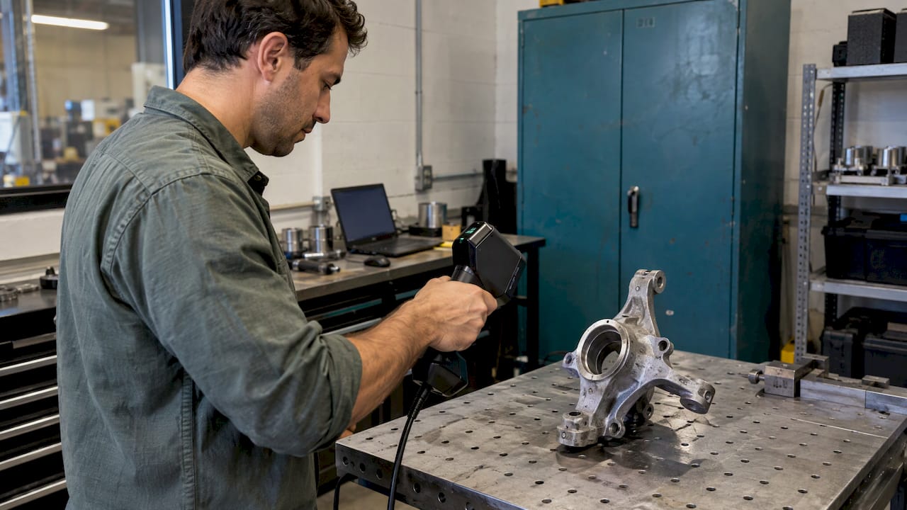
The right 3D scanning service is the one whose scanning method, stated accuracy, deliverable files and downstream CAD capability match what you plan to do with the data. Price matters, but it only means something once those four things line up. This guide walks through how to evaluate a provider for a reverse-engineering, part reproduction or prototyping project, what to put in your request, and how to read the answers you get back.
TL;DR
- Define the end use first: inspection and reverse engineering need far tighter accuracy than visualization or archiving.
- Ask for accuracy in terms of the size of your part, because accuracy typically degrades as the scanned object gets larger.
- Decide on deliverables before the scan: a raw mesh (STL, OBJ, PLY) is not the same as an editable CAD model (STEP, IGES).
- Send a clear request with part size, material, surface finish, tolerances and intended use, so quotes are comparable.
- Choose a provider that can carry the scan through to CAD and, if needed, a printed prototype, so the data never changes hands.
Table of Contents
- Start with what the scan is for
- Understand accuracy, precision and resolution
- Match the scanning method to the part
- Decide on deliverables before the scan
- Check whether the provider can finish the job
- What affects the price and timeline
- How to prepare your request
- Scanning for prototypes: printing or machining?
- Questions to ask any provider
- Our perspective
- Start a scanning project with us
- FAQ
- Sources
Start with what the scan is for
Most bad scanning experiences trace back to a mismatch between the job and the method. A scan made to document a part’s appearance is a different product from a scan made to rebuild a bracket that has to fit a discontinued assembly.
Three common end uses:
- Reverse engineering or part reproduction. You need dimensional fidelity, clean surfaces and usually a CAD model at the end. This is the most demanding case, and the one automotive restorers and product developers run into most often.
- Quality control or inspection. You compare a produced part against its nominal model. Accuracy and repeatability matter most. Our article on scan-based quality control covers how that comparison works.
- Design reference or prototyping. You capture an existing object so a new design can wrap around it, such as an enclosure for an existing component. Moderate accuracy is often enough, as long as critical mating features are captured well.
Write one sentence for your project in this form: “We need [deliverable] of [part] accurate enough to [decision it supports].” Every question below is easier to answer once you have that sentence.
Understand accuracy, precision and resolution
Providers use these three terms loosely, and quotes can look equivalent while describing very different results.
- Resolution is the smallest increment between captured points, usually the point-to-point distance in the mesh. A fine mesh does not make a scan correct.
- Accuracy is how close the scan is to the true size of the object.
- Precision is how well repeated measurements agree with each other.
These definitions are consistent across technical explainers, including Artec’s learning center, which also notes that reverse engineering and quality control put more weight on accuracy and precision than visual applications do.
Ask about volumetric accuracy
A single accuracy figure on a spec sheet usually describes a small area under ideal conditions. Aniwaa’s explainer points out that volumetric accuracy, which describes accuracy across several captures, matters more for larger parts, because overall accuracy diminishes as the part grows. It also lists temperature, calibration, operator skill and the manufacturer’s test standard as factors that affect results.
So instead of asking “how accurate are you?”, ask:
- What accuracy do you expect on a part of my size and shape?
- How do you handle alignment across multiple scan passes on a large part?
- Is the figure a manufacturer spec or something you have verified on similar work?
For our own work, we describe it as professional handheld 3D scanning with accuracy to about 0.1 mm. How that translates to a given part depends on its size, geometry and surface, which is why we discuss it per project. Our guide to what handheld scanner accuracy numbers mean goes into the details, and how to optimize scan accuracy covers the variables you control.
Ask how the result is validated
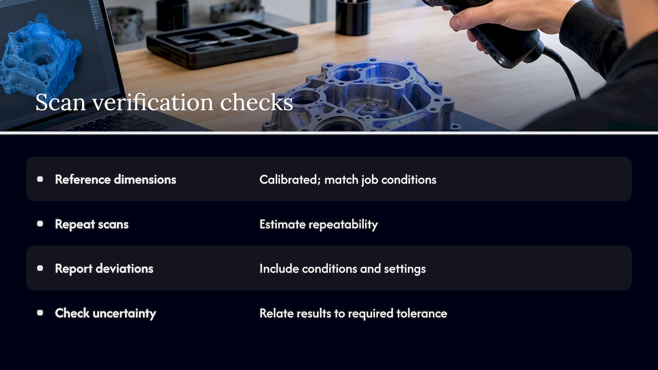
A credible provider can explain how they check a scan. 3DMag’s verification guide recommends validating against calibrated reference dimensions under conditions that match the real job, repeating scans to estimate repeatability, and reporting deviations alongside the conditions and processing settings. The same piece makes a useful point: calibration paperwork is necessary, but it does not on its own show that the uncertainty fits your tolerance. What settles it is whether the provider can relate the measured result to the tolerance you actually need.
If your application is demanding, also ask whether the provider works to a recognized standard such as VDI/VDE or ISO for scanner verification, as the Aniwaa explainer suggests. For many reverse-engineering jobs, a documented check of key dimensions against a caliper or micrometer measurement of the original part is the practical test.
Do not over-specify
Tighter is not always better. If you only need an object’s shape to design a fitting enclosure, paying for the highest accuracy tier adds cost without improving the outcome. Match the specification to the decision the scan supports, and put extra budget into the CAD work that follows.
Match the scanning method to the part
Scanning methods differ in what they handle well. Handheld structured-light and laser scanners are flexible: they capture medium-sized parts, complex curves and objects that cannot be moved to a lab. Fixed-position systems and tracked systems trade flexibility for different accuracy profiles.
Practical questions to ask about method:
- Can the scanner capture the geometry that matters, including deep recesses, thin walls, undercuts and threads?
- How does the provider deal with shiny, dark or transparent surfaces? These often need a temporary matte coating or careful lighting.
- Does the scanner use reference targets, and how does the provider keep alignment stable on large or featureless parts?
Automotive parts are a good example. Cast housings, trim pieces, brackets and manifolds combine large smooth areas with small functional features. A good workflow captures the whole shape and then prioritizes the mounting points, bores and mating faces. Our walkthrough of achieving a high-quality scan for manufacturing shows how that is planned.
Decide on deliverables before the scan
The scan itself is only the raw material. What you receive determines what you can do with it.
| Deliverable | Typical formats | Best for | Limitation |
|---|---|---|---|
| Raw or cleaned mesh | STL, OBJ, PLY | Viewing, 3D printing a copy, comparing against a model | Not parametric; hard to edit dimensions |
| Point cloud | PLY, other point formats | Large-scale capture, software-based inspection | Needs processing before most uses |
| Surface or solid CAD model | STEP, IGES | Reverse engineering, redesign, manufacturing | Requires skilled modeling time |
| Inspection report | PDF, color deviation map | Quality control | Only as good as the reference model and method |
Meshes such as STL, OBJ and PLY can be imported into CAD packages, and reconstructed models are commonly exported as STEP or IGES for use across CAD/CAM tools and manufacturing. If your goal is to change a dimension, add a boss or tune a clearance, a mesh alone will not get you there. You need a rebuilt model.
The step from mesh to editable solid is where much of the effort sits. We explain it in mesh to CAD conversion. For an engineer’s view of the same workflow, this 3D scan to CAD workflow is useful for confirming file compatibility before you commit.
When you request a quote, state the file format you need and the CAD package your team uses. Ask whether the CAD model is delivered as a feature-based model or as a surfaced body, and whether you will receive the original scan data as well. Keeping the raw scan lets you re-verify the CAD model later.
Check whether the provider can finish the job
A scan-only vendor hands you a file and a new problem. A provider that can also model and print lets you validate the result quickly: scan, rebuild, print a test fit, adjust.
This matters for three reasons:
- Fewer handoffs. The person who understood the scan quality is the person building the model.
- Faster correction. If a printed test part does not fit, the cause is traced to the scan, the model or the print in one conversation.
- Better quoting. One provider can describe the whole path rather than leaving you to piece together separate estimates.
At CC 3D Labs, the chain runs from handheld scanning through reverse-engineering CAD to FDM printing on our Bambu Lab farm, with materials including PLA, PETG, ABS, ASA, PC and carbon-fiber nylon. We can also print mold masters from the resulting models. Details on each step are on our services page.
What affects the price and timeline
Scanning is almost always quoted per project, and for good reason. 3DMag’s cost guide lists the factors that make quotes comparable: the required output, tolerance and measurement-uncertainty needs, the size of the object or site, surface and access conditions, onsite logistics, post-processing, and the quality-assurance evidence you want.
In plain terms, two quotes are only comparable if they describe:
- the same deliverable (mesh versus CAD model),
- the same accuracy expectation,
- the same amount of cleanup and modeling,
- the same documentation.
Be careful with any provider that gives a firm price and date from a one-line email. Part complexity, surface condition and the amount of CAD rebuilding vary enormously. We do not publish fixed pricing or blanket turnaround times for that reason. Each job is quoted individually, and for production printing we base the quote on a test print of your actual model.
How to prepare your request
Good inputs get you accurate quotes and fewer surprises. Include:
- Purpose. Reverse engineering, inspection, fit check, reproduction, or design reference.
- Part size and weight, plus how many parts.
- Material and finish. Glossy, dark, translucent or rubbery surfaces can need extra preparation.
- Critical features and tolerances. Mark the dimensions that must be right, such as bore diameters, hole spacing and mating faces.
- Deliverable format. Mesh, STEP, inspection report, or all three.
- Photos and any drawings. Even a hand sketch with a few measured dimensions helps the modeler.
- Delivery method. Local pickup or shipping, and how the part will be returned.
- Downstream plan. Will you print it, machine it, or mold it?
Physical preparation helps too. Clean the part of grease, dirt and rust, and flag anything fragile. Our 3D scanning checklist lists the preparation steps in order, and the guide on scanning objects for 3D printing shows how scan choices carry into printing.
Pro Tip: If the part is worn or damaged, send a second, undamaged example if you have one. The modeler can then rebuild the intended geometry rather than the worn one.
Scanning for prototypes: printing or machining?
Many scanning projects end in a prototype, so the process choice comes up. The two common routes are additive (3D printing) and subtractive (CNC machining), and they suit different priorities.
| Consideration | FDM 3D printing | CNC machining |
|---|---|---|
| Geometry | Internal channels, organic shapes and lattices are practical | Shapes must be reachable by a cutting tool |
| Iteration | Design changes mean a new print file | Design changes usually mean new toolpaths and setup |
| Typical tolerance | About ±0.2 to 0.5 mm for FDM | Generally tighter, depending on machine and material |
| Materials | Engineering thermoplastics for FDM | Wide range, including metals |
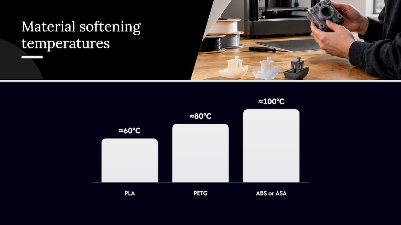
For form, fit and function checks on plastic parts, FDM is well suited, particularly when you expect several design revisions. Material choice matters for heat: PLA softens at roughly 60°C, PETG at about 80°C and ABS or ASA at about 100°C, which are approximate averages and not guarantees for a given part. If a part will sit near an engine bay or a heat source, material selection should be part of the scanning conversation. Our prototyping workflow guide and rapid prototyping overview cover how to sequence these decisions.
A scan-derived CAD model is process-neutral, so the same file can support whichever route your project needs.
Questions to ask any provider
Use this list when comparing providers:
- What accuracy do you expect for a part like mine, and how do you verify it?
- What formats do I receive, and do I keep the raw scan data?
- Who builds the CAD model, and how is it checked against the scan?
- How do you handle shiny or dark surfaces?
- How is the quote built, and what could change it?
- Can you print a test part to confirm fit?
- How do you handle shipping, packaging and return of my original part?
- What will you tell me if the part is a poor candidate for scanning?
A provider who answers specifically, with reference to your part, is usually one who has done similar work.
Our perspective
We built CC 3D Labs around a simple observation: most scanning problems are really handoff problems. A scan arrives as a mesh, someone else has to rebuild it, and a third party prints it. Each step loses context, and the part that comes back does not fit.
Our approach is to keep the chain short. We scan with professional handheld equipment (accuracy to about 0.1 mm), rebuild the geometry in CAD, and print a test part on our Bambu Lab farm so you can check fit in your hand before committing to a run. We are owner-operated, so you talk to the person doing the work, and we take on awkward jobs, fragile originals and legacy parts that others have turned down.
We also prefer to be plain about what we do not know until we see the part. That is why we quote individually rather than posting a price list. A cast housing and a thin plastic clip are different problems, and the quote should reflect that.
Justin
Start a scanning project with us
CC 3D Labs is a 3D scanning and printing service in the Greater Philadelphia area (Bucks County, PA). Local customers can use residential pickup, since we do not run a walk-in storefront, and finished orders ship anywhere in the United States. We work with automotive shops and restorers, product developers, engineers and small businesses that need scanning, reverse engineering, prototypes or low-volume parts. See our 3D scanning lab for the full scope.
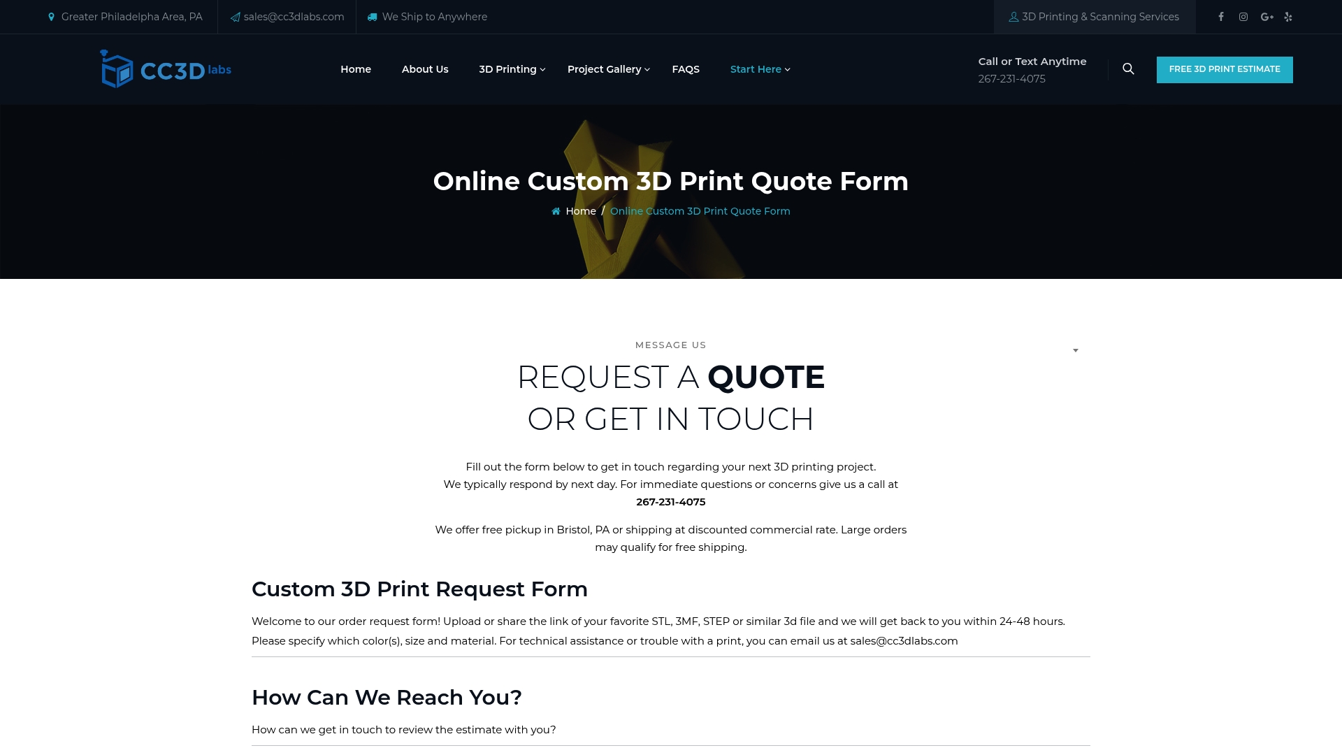
To get a quote, send the details from the checklist above through our 3D scan request form. If you also need printed parts, use the 3D print quote form, and for modeling work, the CAD quote form.
FAQ
Is a mesh file enough, or do I need a CAD model?
A mesh is enough if you want to view the part, compare it against a design or print a copy. If you need to edit dimensions, adjust tolerances or send the part to manufacturing, you need an editable CAD model, typically delivered as STEP. Tell the provider which one you need when you request the quote.
How accurate does my scan need to be?
It depends on the decision the scan supports. Reverse engineering and inspection call for higher accuracy and repeatability than visual capture. Identify the tightest tolerance on your part and ask the provider how they would verify that dimension.
Can a scan be used to 3D print a replacement part?
Yes, in most cases the scan is cleaned, rebuilt into a model and printed in a material chosen for the part’s load and temperature. FDM printing typically holds about ±0.2 to 0.5 mm, so critical mating features are often designed with that in mind. A test print confirms the fit before any larger run.
Why don’t you list prices for scanning?
Cost depends on part size, surface condition, the accuracy you need, the amount of CAD rebuilding and the documentation you want. We quote each job individually so the estimate describes your actual part.
What should I send with my request?
Send the purpose of the scan, part dimensions, material and finish, critical features, the file formats you need and a few photos. Drawings or measurements help. If you can, send an undamaged example of a worn part as well.
Sources
- 3D scanner accuracy and resolution: What you need to know (Aniwaa)
- 3D scanner accuracy vs resolution and precision, and how to verify (3DMag)
- 3D scanning accuracy, precision and resolution (Artec)
- 3D scanning services cost, quotes, accuracy and hiring (3DMag)
- 3D scan to CAD: a practical workflow for engineers