TL;DR:
- Achieving true precision in 3D printing involves controlling tolerances, surface finish, and internal integrity throughout the entire process.
- Effective collaboration between designers and manufacturers, along with comprehensive inspection methods like CT scanning, ensures consistent, high-quality parts ready for critical applications.
Understanding the qualities of precision 3D parts separates engineers who get functional assemblies right the first time from those who spend weeks chasing tolerance failures. Precision in additive manufacturing is not simply “the printer is accurate.” It covers dimensional tolerance control, surface integrity, material behavior, process repeatability, and post-processing effects working together. This article breaks down the specific technical characteristics that define a truly precise 3D printed part, how different technologies compare, and what process controls actually move the needle for engineers and product developers in 2026.
Table of Contents
- Key takeaways
- 1. The core qualities of precision 3D parts defined
- 2. Tight dimensional tolerances and their effect on fit and function
- 3. Consistent surface finish and low roughness metrics
- 4. Feature resolution and minimum wall thickness
- 5. Volumetric integrity verified through CT scanning
- 6. Material homogeneity and post-processing effects
- 7. Comparison of printing technologies by precision capability
- 8. Best practices and process controls for achieving precision
- My honest take on precision in additive manufacturing
- How Cc3dlabs helps you achieve precision in every part
- FAQ
Key takeaways
| Point | Details |
|---|---|
| Tolerance defines function | High-precision parts target ±0.05 mm to ±0.1 mm, but the full print-to-finish process determines final dimensional accuracy. |
| Technology choice matters | SLA and DLP deliver the tightest tolerances; SLS and DMLS trade some precision for structural complexity. |
| Precision includes the interior | CT scanning per ASTM standards reveals internal defects that surface measurement alone cannot catch. |
| DfAM reduces tolerance failures | Design for Additive Manufacturing strategies like strategic orientation and fillets prevent warping and dimensional drift. |
| Post-processing is part of precision | Shrinkage, curing, and finishing steps materially affect final dimensions and must be controlled, not assumed. |
1. The core qualities of precision 3D parts defined
Most engineers use “precision” as a catch-all, but manufacturing distinguishes three separate concepts: accuracy, precision, and repeatability. Accuracy means the part hits its nominal dimension. Precision means it hits the same dimension consistently across multiple prints. Repeatability means the entire process produces identical results across batches, machines, and operators.
High-precision printed parts commonly target dimensional tolerances of ±0.05 mm to ±0.1 mm, with layer heights as thin as 10 to 25 µm and surface roughness (Ra) values low enough to meet optical and medical standards. Industrial-grade systems achieve this through advanced process controls and active compensation for material shrinkage and thermal effects.
- Dimensional tolerance: The allowable deviation from nominal geometry, typically expressed as ±X mm
- Surface roughness (Ra): Average surface deviation in micrometers, directly affecting fit, friction, and sealing
- Repeatability: Part-to-part consistency across a production run, not just a single successful print
- Layer adhesion integrity: Uniform bonding between layers that prevents delamination under load
- Build orientation effect: How the angle of a part on the build plate impacts anisotropic strength and dimensional accuracy
Pro Tip: When specifying tolerances for a printed part, always call out which surfaces are functional and which are cosmetic. Applying ±0.05 mm across an entire part inflates cost with no engineering benefit.
2. Tight dimensional tolerances and their effect on fit and function
Dimensional tolerance is the quality that most directly determines whether a part works in an assembly. A shaft that is 0.15 mm oversized will not seat in its bearing. A snap-fit feature that is 0.2 mm too thin will fail after three cycles.
For functional moving parts, engineered clearances of 0.2 to 0.4 mm are required in FDM to prevent fusion between adjacent surfaces during printing and enable proper articulation. This is not a flaw of the process. It is a designed-in reality that engineers must account for during modeling.
The important distinction is between as-printed tolerance and final tolerance. Shrinkage, curing, and finishing steps can materially alter final dimensional accuracy. A part that measures within spec on the build plate may drift outside tolerance after thermal post-processing. Treating the full workflow as a single controlled capability, not just the print stage, is what separates production-ready precision from prototype luck.
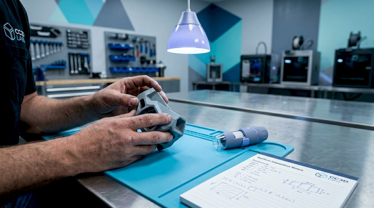
3. Consistent surface finish and low roughness metrics
Surface finish affects more than aesthetics. It governs sealing performance, friction in moving assemblies, fatigue life under cyclic loading, and adhesion in bonded joints. Ra values below 1.6 µm are achievable with resin-based processes; industrial FDM typically produces Ra values between 6 and 25 µm before post-processing.
Post-processing methods change this significantly. Vapor smoothing reduces surface roughness in FDM parts by 70 to 90 percent in some cases. Bead blasting improves surface uniformity in SLS parts while reducing friction in joints. CNC machining of critical surfaces brings any printed part to sub-micron roughness when required.
The practical implication: specify surface finish by Ra value on your technical drawing, not by process. Let the manufacturer select the combination of printing and finishing that hits the number. You get better results and more flexibility in sourcing.
4. Feature resolution and minimum wall thickness
Fine features are where many additive processes fail quietly. A design that looks correct in CAD can lose detail, round edges, or merge adjacent features when translated into physical layers.
Minimum wall thickness for FDM typically runs 0.8 to 1.2 mm for structural reliability. SLA and DLP push that down to 0.3 to 0.5 mm. DMLS for metal parts holds around 0.3 to 0.4 mm. These numbers change with build orientation: walls parallel to the Z axis are generally thinner and more fragile than walls built horizontally.
The characteristics of high-quality 3D models include geometry that accounts for these physical limits. Features that are thinner than the process minimum either print poorly or not at all. Reviewing your model against the capabilities of your chosen process before sending it to print saves significant rework time.
5. Volumetric integrity verified through CT scanning
External dimensional inspection only tells part of the story. Internal porosity, incomplete fusion, entrapped powder, and micro-cracks are invisible to calipers and CMMs. These defects are particularly consequential in aerospace, medical, and pressure-vessel applications where internal flaws cause catastrophic failure.
CT inspection for additive manufacturing provides volumetric nondestructive testing for internal defects and dimensional verification beyond surface measurement, guided by ASTM standards E3166 and F3624. It reveals porosity and lack-of-fusion defects that are essential to catch in aerospace and medical quality assurance workflows.
This is not just an inspection technique. It is a process feedback tool. When CT results show consistent porosity at a specific layer height, that points directly to a process parameter issue. Catching it early across a batch prevents an entire production run from failing qualification.
Pro Tip: For certification-bound parts, request a CT scan report as part of your first article inspection package. It closes the loop between dimensional compliance and internal integrity in a single document.
6. Material homogeneity and post-processing effects
Material behavior during and after printing directly shapes the final precision of a part. Polymers shrink as they cool. Resins shrink during UV curing. Metals contract during sintering and heat treatment. Each process has a characteristic shrinkage profile that must be compensated in the pre-print CAD model.
Tight tolerances in metal additive manufacturing require thermal control, pre-compensated CAD models, and rigorous post-print inspection to avoid dimensional failures in aerospace and medical implants. That compensation is not a one-time correction. It is a machine-specific, material-specific, geometry-specific calibration that changes when any of those variables change.
Material homogeneity also matters for anisotropic strength. FDM parts are measurably weaker in the Z axis than in XY due to layer-to-layer bonding mechanics. Knowing this allows you to orient critical load paths in the XY plane at the design stage, rather than discovering the failure mode during testing.
7. Comparison of printing technologies by precision capability
Different processes achieve different tolerance levels, and selecting the right one for your precision requirement is a core decision. Here is a direct comparison of the major technologies:
| Technology | Typical tolerance | Min feature size | Best use cases |
|---|---|---|---|
| SLA | ±0.05 mm | 0.3 mm | Dental, optics, microfluidics |
| DLP | ±0.05 mm | 0.3 mm | Jewelry, hearing aids, small complex parts |
| PolyJet | ±0.05 mm | 0.2 mm | Multi-material prototypes, overmold simulation |
| SLS (polymer) | ±0.1 to 0.2 mm | 0.5 mm | Functional parts, complex geometry, no supports |
| DMLS (metal) | ±0.1 to 0.2 mm | 0.3 mm | Aerospace, medical implants, tooling |
| Industrial FDM | ±0.1 to 0.2 mm | 0.8 mm | Structural prototypes, jigs, fixtures |
Resin-based technologies like SLA and DLP offer tolerances around ±0.05 mm with fine feature resolution, making them ideal for dental and microfluidic applications. Powder-based processes like SLS and DMLS achieve slightly broader tolerances but excel in functional structural parts with complex internal geometry.
Choosing the right process means matching tolerance capability to the function of the part. For a consumer product prototype, industrial FDM may be entirely sufficient. For a flight-critical bracket, DMLS with CT verification is the correct choice. Review the full technology comparison guide before committing to a process for a new program.
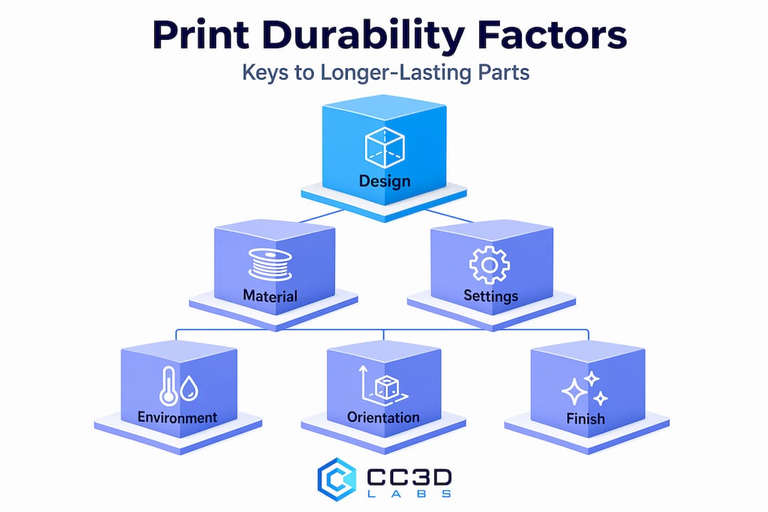
8. Best practices and process controls for achieving precision
Achieving precision in additive manufacturing requires controlling inputs at every stage of the workflow:
- Apply DfAM principles from the start. Design for Additive Manufacturing strategies such as adding fillets, minimizing large flat surfaces, and orienting parts on the XY plane reduce warping and dimensional drift before the printer ever starts.
- Use software compensation for shrinkage. Pre-scale the CAD model based on known material shrinkage coefficients for the specific machine and material combination. This is especially critical in metal DMLS and photopolymer SLA.
- Control the build environment. Temperature, humidity, and machine calibration directly affect dimensional output. Well-maintained machines with calibrated build plates produce measurably tighter results than machines running with drift.
- Implement CT inspection for functional parts. CT per ASTM standards ensures repeatability and certification readiness beyond typical surface metrology.
- Document traceability per AS9102 Rev C. AS9102 Rev C standards establish requirements for characteristic accountability in first article inspection, including nominal values, tolerances, GD&T callouts, and verification outcomes for each design characteristic.
- Plan post-processing as a controlled step. Vapor smoothing, reaming, bead blasting, and CNC finishing are not afterthoughts. Each one affects final dimensions. Budget tolerances accordingly.
Pro Tip: Build a tolerance stack-up analysis before finalizing your 3D printing process. Account for the as-printed tolerance, expected shrinkage, and the effect of any finishing steps. That stack-up tells you whether your process is capable before you print a single part.
Understanding tolerances in 3D printing at the engineering level is the single most effective way to close the gap between what your CAD model shows and what you hold in your hand.
My honest take on precision in additive manufacturing
I’ve worked with enough engineers and product developers to know that the word “precision” gets used loosely. A lot of projects arrive at the printer with tight tolerances applied uniformly across the entire part drawing, with no post-processing plan and no inspection defined. Then everyone is surprised when the part doesn’t fit.
In my experience, the biggest precision failures don’t come from the printing process itself. They come from treating the print as the final step. Shrinkage, curing, and finishing steps materially affect final accuracy, and ignoring that reality costs time and money on every program.
What I’ve also seen is that CT scanning changes the conversation entirely for functional parts. CT inspection reveals internal defects that surface checks miss completely, and in aerospace and medical programs, that is the difference between a part that certifies and one that doesn’t.
My honest recommendation: get your designer and your manufacturer talking at the start of the project, not after first print failure. The best precision outcomes I’ve seen come from that collaboration. The worst come from throwing a completed drawing over the wall and expecting the printer to sort it out.
— Justin
How Cc3dlabs helps you achieve precision in every part
When precision is not optional, the process behind the print matters as much as the machine. Cc3dlabs brings together advanced FDM printing, metrology-grade 3D scanning, and design support to help engineers and manufacturers hit their tolerance and quality targets from the first production run.

Whether you need a single prototype validated against your CAD model or a batch of functional parts with documented first article inspection, Cc3dlabs provides the precision 3D printing services and inspection capabilities to back it up. Their team can assist with material selection, DfAM reviews, post-processing planning, and 3D scanning verification to confirm dimensional compliance before anything ships. From concept validation to production-ready components, Cc3dlabs delivers the technical depth that precision programs demand.
Get a free online estimate and find out how Cc3dlabs can support your next precision project.
FAQ
What tolerance is considered precision in 3D printing?
High-precision 3D printed parts target dimensional tolerances of ±0.05 mm to ±0.1 mm, depending on the technology. SLA and DLP processes achieve the tighter end of that range, while FDM and SLS typically operate toward ±0.1 to 0.2 mm without post-processing.
How do I verify precision in a 3D printed part?
Surface metrology with calipers or a CMM covers external dimensions, but CT scanning per ASTM standards E3166 and F3624 is required to verify internal integrity and catch porosity or fusion defects invisible to surface measurement.
Does post-processing affect final dimensional accuracy?
Yes. Shrinkage, curing, vapor smoothing, and CNC finishing all alter final part dimensions. The full print-to-finish workflow must be treated as a single controlled capability, not isolated stages.
Which 3D printing technology is most precise?
Resin-based technologies, specifically SLA, DLP, and PolyJet, deliver the tightest tolerances around ±0.05 mm and are best for fine-feature applications. DMLS leads in metal precision for structural and certification-critical components.
What is DfAM and why does it matter for precision?
Design for Additive Manufacturing (DfAM) is the practice of adapting geometry to suit additive process constraints. Strategic orientation, fillets, and support design reduce warping and dimensional drift, directly improving the precision of the printed part without changing the machine or material.