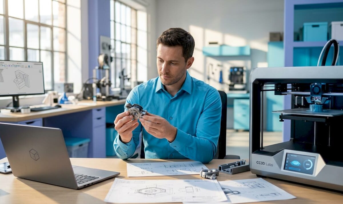
Engineer reviewing 3D printer at workbench

Fast Turnaround 3D Printing: Why Speed Wins in 2026


TL;DR:

  • Rapid 3D printing enables product teams to test prototypes in days, accelerating development cycles.
  • Speed often involves trade-offs in surface quality, but can still produce functional, test-ready parts.
  • Integrating fast printing into workflows boosts innovation, reduces risks, and shortens time to market.

When traditional manufacturing quotes come back with 6 to 12 week lead times, product teams lose momentum before a single part is tested. Fast turnaround 3D printing flips that dynamic entirely, delivering functional prototypes in days rather than months. But many engineers still assume that speed means compromise, that you’re trading surface quality or structural integrity for convenience. That assumption is worth challenging. This article breaks down how rapid 3D printing actually works, where it creates real competitive advantage, what trade-offs are genuinely worth managing, and how to build it into your development workflow without guessing.

Table of Contents

Key Takeaways

Point Details
Speeds up innovation Rapid 3D printing shrinks the time from idea to prototype to just days.
Manages trade-offs Balancing speed, quality, and cost helps teams iterate faster without sacrificing function.
Enables market advantage Using fast 3D prints for early concepts helps outpace competitors and test ideas quickly.
Works across industries Automotive, medical, and electronics companies all benefit from shorter production cycles.

The impact of speed: From concept to prototype in days

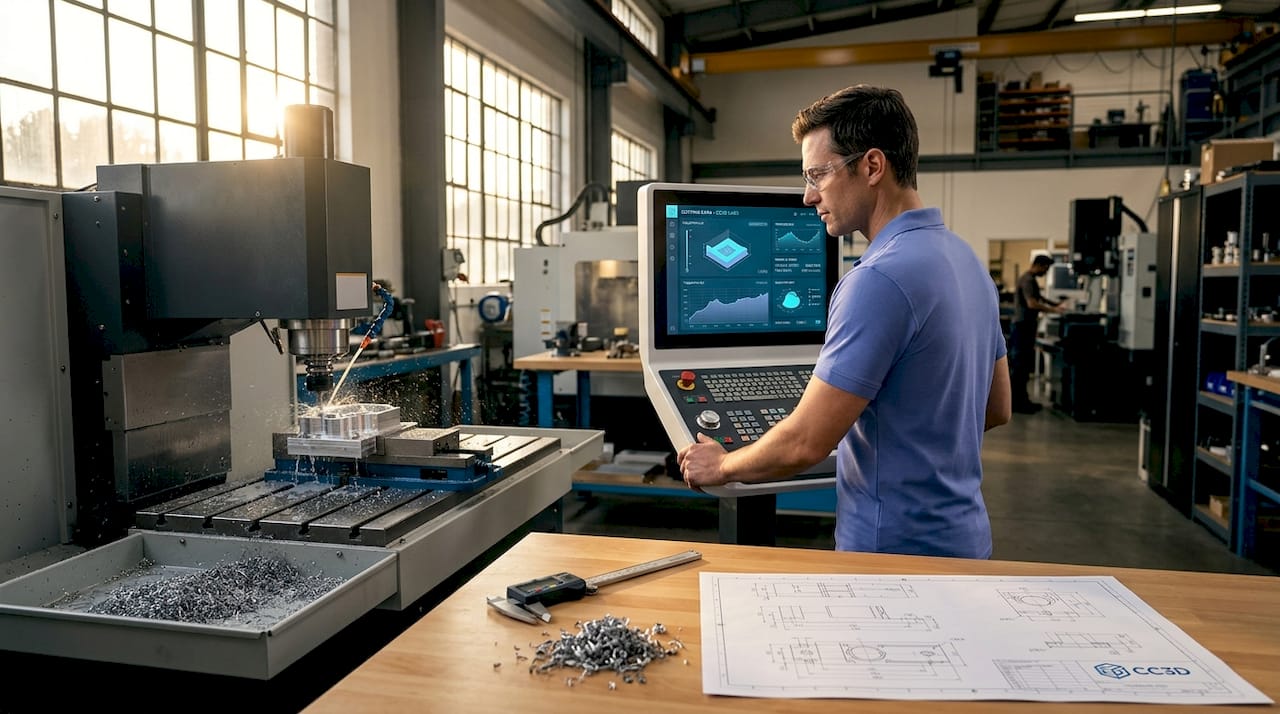
Traditional manufacturing methods like CNC machining and injection molding are built for precision at scale, not iteration. A single mold can cost tens of thousands of dollars and take 8 to 16 weeks to produce. For a product team running design cycles, that’s not a delay. It’s a full stop.

Fast turnaround 3D printing changes the math. Instead of waiting weeks for each revision, teams can receive updated prototypes in 24 to 72 hours. That kind of speed enables something traditional manufacturing simply can’t: parallel development. You can test three different geometry variations at the same time, gather real feedback, and move forward with data instead of guesses.

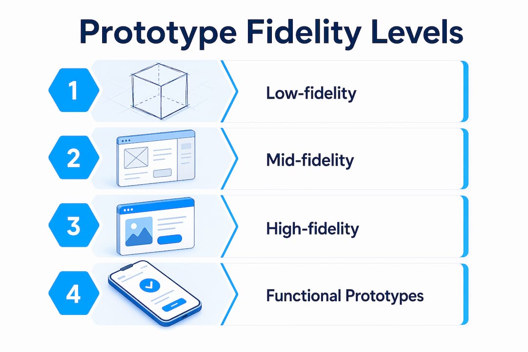
One common misconception is that fast prints are only useful for visual mockups. That’s not accurate. With the right material and settings, fast-printed parts can handle functional testing, fit checks, and even early stress validation. The key is understanding where speed is appropriate in your process. Our rapid prototyping guide covers this in detail for teams just getting started.

Print parameters drive the speed-quality relationship directly. Thicker layers at 0.2mm print faster but produce a rougher surface finish, while lower print speeds in the 20 to 40mm/s range deliver better dimensional accuracy. Neither is universally better. The right choice depends on what stage of development you’re in.

Here’s what fast turnaround printing actually enables for product teams:

  • Faster design validation without waiting for machining queues
  • Multiple simultaneous iterations tested in parallel
  • Lower cost per learning cycle compared to traditional tooling
  • Earlier cross-team collaboration with physical parts in hand
  • Reduced risk before committing to expensive production tooling

“The real cost of slow prototyping isn’t the machining bill. It’s every week your competitor spends iterating while you’re waiting.”

Pro Tip: Use fast-turnaround prints for early-stage concept testing where surface finish is secondary. Reserve high-resolution settings for later rounds when fit, form, and finish all matter. This approach saves time and budget without sacrificing the learning you need.

For teams that also need dimensional verification of existing parts, quality 3D scans can feed directly into your CAD revision process, closing the loop between physical testing and design updates.

Balancing speed, quality, and cost: Key considerations

Once you understand how much time fast printing saves, the next question is what you’re actually trading for that speed. The answer is more nuanced than most people expect.

Technician adjusts FDM printer settings in workshop

Print speed in FDM (fused deposition modeling) is controlled by three primary variables: layer height, print speed setting, and temperature. Pushing all three toward maximum output produces parts faster, but the surface finish suffers. Thicker layers and faster speeds mean visible layer lines and reduced detail on fine features. For a concept test, that’s perfectly acceptable. For a customer-facing prototype, it probably isn’t.

Surface finish varies significantly across printing technologies. Here’s a comparison that matters when you’re choosing a process:

Technology Surface finish Ra Best for
SLA 1 to 5 μm High-detail visual prototypes
MJF 5 to 10 μm Functional parts, complex geometry
SLS 10 to 15 μm Durable, end-use parts
FDM 15 to 50 μm Fast concept models, structural tests

Infographic on 3D printing speed quality cost

Surface finish Ra values show that chemical smoothing post-processing can significantly improve FDM results when needed. That gives you a useful middle path: print fast, then smooth selectively.

Here’s a practical numbered approach for deciding which speed setting to use:

  1. Define the part’s purpose. Is it a concept check, a fit test, or a functional prototype?
  2. Identify the critical features. Do fine details or surface quality matter for this round?
  3. Set your deadline. If you need the part in 24 hours, high-resolution settings may not be feasible.
  4. Choose layer height accordingly. 0.2mm for speed, 0.1mm or finer for detail.
  5. Plan post-processing. If finish matters, budget time for sanding or chemical smoothing.

For teams managing tight schedules, our low-volume manufacturing tips walk through how to structure print batches efficiently. And if you need parts on demand without maintaining in-house equipment, 3D printing on demand is often the fastest path from file to physical part.

Pro Tip: On projects with hard deadlines, run fast prints for structural and fit testing while simultaneously ordering high-resolution prints for the customer-facing version. You get both timelines working in parallel.

Applications where speed creates competitive advantage

Knowing the trade-offs is one thing. Seeing where fast printing actually moves the needle on commercial outcomes is another.

Automotive teams use rapid 3D printing to validate bracket designs, duct geometries, and interior trim components before committing to tooling. A design verification cycle that once took 8 weeks can now run in under a week. Medical device developers use it to test ergonomics, housing fits, and assembly sequences on physical models before regulatory submission. Consumer electronics teams print enclosures and button assemblies to test user interaction before any injection mold is cut.

Industry Typical turnaround Key impact
Automotive 1 to 3 days per iteration Faster design freeze, reduced tooling risk
Medical devices 2 to 5 days Earlier ergonomic validation, lower rework cost
Consumer electronics 1 to 2 days Faster user testing, more design options explored
Industrial equipment 2 to 4 days Quicker fit checks before machining

The competitive benefits stack up quickly:

  • Faster time to market by compressing the design verification phase
  • More design options explored without proportional cost increases
  • Lower financial risk before tooling investment
  • Better cross-functional alignment when everyone holds a physical part
  • Earlier identification of design flaws before they become expensive

Surface finish data across technologies helps teams match the right process to the right stage, ensuring you’re not over-engineering early prototypes or under-specifying final validation parts.

Exploring the full range of 3D printing applications shows just how broad the use cases have become across industries. Staying current with 3D printing trends also helps teams anticipate which capabilities are worth building into their standard workflow now.

Pro Tip: Use rapid prints to test market fit with real users before finalizing a design. A physical part in a customer’s hands during early-stage research is worth more than any survey.

Integrating fast 3D printing into your workflow

Understanding the value is step one. Building a repeatable process around it is where teams actually capture that value consistently.

The first decision is identifying which parts and project stages are good candidates for rapid printing. Not everything benefits equally. Early-stage concept models, fit-check assemblies, and ergonomic test pieces are ideal. Highly detailed cosmetic parts or components requiring tight tolerances may need slower, higher-resolution settings regardless of schedule pressure.

File preparation matters more than most teams realize. Clean STL files with proper wall thicknesses, no inverted normals, and appropriate support structures reduce print failures and reprints. A file that takes 20 minutes to prepare correctly can save hours of troubleshooting later.

Here’s a straightforward numbered workflow that works well for most product development teams:

  1. Upload or share your CAD/STL file with your print service or internal team.
  2. Select material and speed settings based on the part’s purpose in this iteration.
  3. Confirm print time and delivery window before committing.
  4. Print and receive the part, typically within 1 to 3 business days for fast-turnaround jobs.
  5. Test, document findings, and revise the design file based on physical feedback.
  6. Repeat the cycle until the design meets validation criteria.

“From file upload to part in hand, the fastest teams treat each print cycle as a structured experiment, not just a manufacturing step.”

For teams without in-house equipment, on-demand 3D printing removes the machine management burden entirely. You upload, we print, you iterate. The parameter relationship between layer height and speed means your service provider should be able to recommend the right settings based on your stated goals, not just default profiles.

If dimensional accuracy is critical for your parts, pairing rapid printing with design accuracy tools like 3D scanning closes the feedback loop and ensures each revision is grounded in measured data, not visual inspection alone.

Why most teams underestimate the value of speed

Here’s an uncomfortable observation: most product teams calculate the value of fast prototyping by looking at the cost of a single print run. That’s the wrong unit of measurement.

The real value is in learning cycles. Every iteration you complete before a competitor completes one is a compounding advantage. You’re not just saving time on one part. You’re accumulating insights, eliminating bad options faster, and building team confidence through physical evidence rather than CAD assumptions.

Most companies overestimate the quality loss from fast printing and underestimate the strategic loss from slow iteration. A slightly rougher prototype that gets tested Tuesday beats a perfect model that arrives next month. The teams that internalize this shift their entire development culture, not just their print settings.

Rapid printing also fuels creative risk-taking. When a new idea costs two days and a modest print fee instead of six weeks and a tooling budget, engineers propose more ideas. That’s not a side effect. It’s the point. Real on-demand prototyping makes experimentation affordable enough to become a habit.

“The teams who ship fastest win, not just the market, but the insights game.”

Unlock rapid prototyping with CC3DLabs

Ready to put fast-turnaround 3D printing into action? CC3DLabs helps product developers and engineering teams near Philadelphia and beyond get functional parts and prototypes fast, without sacrificing the accuracy your project demands.

https://cc3dlabs.com

We handle everything from single concept prints to low-volume production runs, with material selection guidance and quick turnaround built into every order. Whether you need a fit-check part by Thursday or a batch of functional assemblies for a client demo, we’re set up to move at your pace. Explore 3D printing services to see what’s available, check out what’s possible with 3D printing for inspiration, or go straight to start a fast 3D print project and get your estimate today.

Frequently asked questions

Does faster 3D printing always mean lower quality?

Not always. Thicker layers and faster speeds reduce surface finish, but most experienced teams use fast prints for early iterations and switch to high-resolution settings only when fit, finish, and detail all matter.

What industries benefit most from rapid 3D printing?

Automotive, medical devices, and consumer electronics gain the most, particularly during design verification and short-run functional testing where iteration speed directly affects time to market.

How fast can I get a functional 3D printed part?

With fast-turnaround printing, functional prototypes can be delivered in as little as 1 to 3 business days depending on part complexity, material, and order volume.

What are the key trade-offs when choosing speed?

Choosing faster settings typically means reduced surface resolution and visible layer lines, but the time savings across multiple iterations far outweigh the finish compromise for most early-stage development work. Surface finish Ra values vary significantly by technology, so matching the process to the project stage is the smarter move.

Can I outsource fast turnaround 3D printing?

Yes. Service bureaus like CC3DLabs offer rapid printing for prototypes and low-volume runs with no machine availability delays, giving you faster access to parts than most in-house setups can provide.

Engineer oversees 3D printing prototype process

Step-by-Step 3D Printing: Guide to Quality Prototypes


TL;DR:

  • Proper setup and material choice are essential to prevent common 3D print failures.
  • Workflow stages from CAD to testing greatly influence prototype accuracy and reliability.
  • Continuous iteration and analysis of failures lead to better scaling and production-ready parts.

Turning a digital design into a functional prototype feels straightforward until your first print warps off the bed, critical holes print undersized, or a snap-fit snaps wrong. Every stage of the 3D printing workflow carries real consequences for product developers and engineers: a miscalibrated printer or a poorly sliced file can cost you days and materials. This guide walks you through the full process, from CAD modeling to final evaluation, with expert-backed strategies, troubleshooting shortcuts, and optimization tips that help you build reliable, repeatable results. Whether you’re prototyping a single concept or preparing for batch production, the framework here is built to reduce risk at every step.

Table of Contents

Key Takeaways

Point Details
Plan before printing Success depends on preparing your CAD model, picking the right material, and verifying all printer settings and requirements.
Follow a proven workflow Move step-by-step from design to slicing, material choice, printing, post-processing, and testing for repeatable quality.
Optimize with iteration Expect to run two to four prototype cycles, incorporating testing feedback each time before moving to production.
Avoid common pitfalls Check for undersized holes, wall thickness, and correct build orientation to reduce failures and improve performance.
Leverage expert resources When in doubt, consult specialized guides or service providers to troubleshoot, optimize, and scale your 3D printing process.

Understand prerequisites and materials for 3D printing success

Before you print a single layer, your workflow needs a solid foundation. The standard prototyping process covers CAD modeling, slicing, material selection, printing, post-processing, and evaluation. Skipping or rushing any of these stages is where most prototype failures originate. Getting your tools, materials, and knowledge aligned upfront is the fastest way to avoid expensive rework later.

Here’s what you need in place before starting:

  • 3D printer: Calibrated, with a verified build plate level and nozzle condition
  • CAD software: Fusion 360, SolidWorks, or equivalent with export to STL/STEP
  • Slicer software: PrusaSlicer, Cura, or Chitubox depending on your technology
  • Filaments or resin: Matched to your functional requirements (PLA for concept models, PETG or Nylon for functional parts)
  • Post-processing tools: Deburring tools, sandpaper, IPA for resin, heat gun for warping correction
  • Calipers: Digital, for dimensional verification after every print

Material and tool selection is where engineers often underestimate complexity. Choosing PLA because it’s easy to print, then testing it under load, is a common mismatch. If you’re designing reliable 3D prints, material selection must track directly to end-use conditions, not just printability.

Tool/Material Purpose Best prototype stage
FDM printer (0.4mm nozzle) Concept and functional prototypes Early to mid stage
PLA/PETG filament Form and fit testing Concept to functional
Nylon/ASA filament Mechanical and environmental testing Functional validation
Resin (SLA) High-detail, tight-tolerance parts Fit checks, visual models
Digital calipers Dimensional verification All stages
Slicer software Toolpath and support generation All stages

For a deeper breakdown of material options and print settings, the filament printing guide covers the most common engineering filaments and when to use each.

Infographic showing 3D printing materials and tips

Pro Tip: Always run a printer calibration check, including first-layer height and extrusion multiplier, before starting any new material or batch. A 5-minute check prevents hours of failed prints.

Step-by-step process: From CAD to finished part

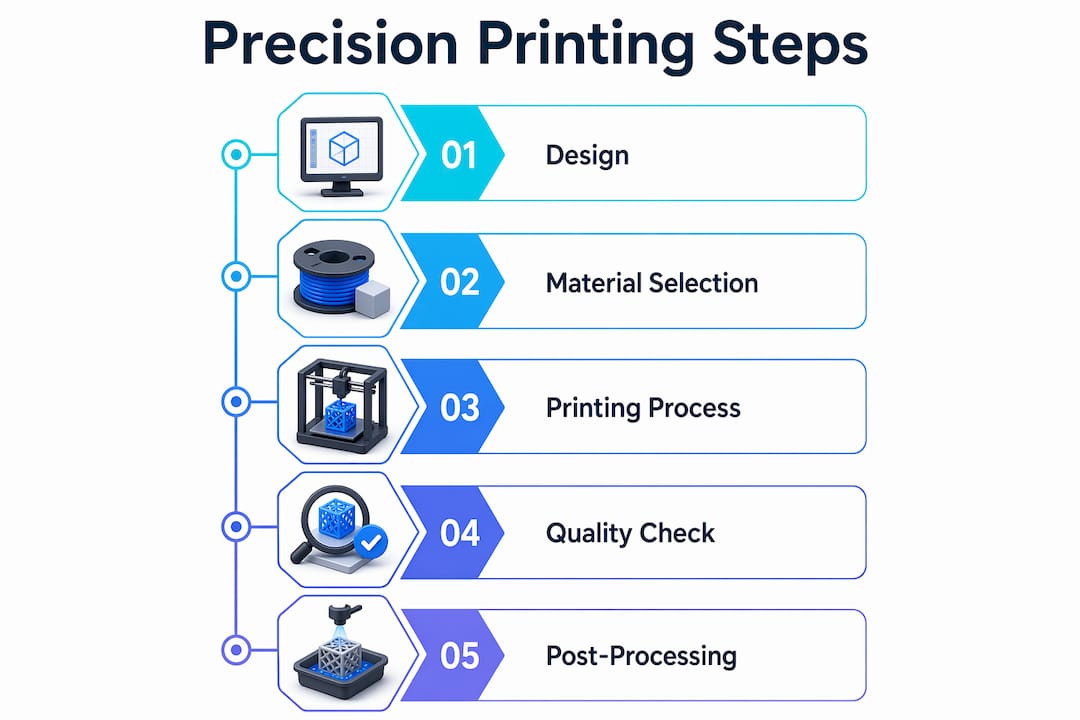
With the right setup, you’re ready to move through each key phase with confidence. The end-to-end workflow follows six stages: CAD modeling, slicing, technology and material selection, printing, post-processing, and testing. Each phase feeds the next, so a weak link early compounds downstream.

  1. CAD modeling: Design with manufacturing in mind. Wall thicknesses above 1.2mm for FDM, clearances of 0.2 to 0.4mm for mating parts, and no unsupported overhangs beyond 45 degrees.
  2. Slicing: Convert your STL to toolpaths. Set layer height, infill, supports, and print speed. Layer height is the vertical resolution of each printed layer, typically 0.1 to 0.3mm for FDM.
  3. Technology and material selection: Match the process to the requirement. Use choosing the right 3D printing process as a reference when requirements shift.
  4. Printing: Monitor the first few layers. Adhesion failures and stringing are easiest to catch and correct early.
  5. Post-processing: Remove supports, sand critical surfaces, cure resin parts under UV, or anneal Nylon for dimensional stability.
  6. Testing and iteration: Measure, fit-check, and stress-test before moving to the next design revision. Review rapid prototyping fundamentals for structured iteration strategies.

Understanding the differences between technologies is critical. Mechanical property studies confirm that process choice directly impacts part strength and isotropy (uniformity of mechanical properties in all directions).

Technology Typical tolerance Layer height Relative cost Best use
FDM ±0.2 to 0.5mm 0.1 to 0.3mm Low Functional, structural prototypes
SLA ±0.05 to 0.15mm 0.025 to 0.1mm Medium High-detail, tight-fit parts
SLS ±0.1 to 0.3mm 0.1mm High Durable, complex geometry

The FDM vs SLA vs SLS comparison shows that tolerances, costs, and mechanical properties vary significantly across technologies, so aligning your choice to your validation stage matters.

Pro Tip: Print a small test coupon, a simple block with the key features of your part, before committing to a full prototype run. This catches fit and tolerance issues in under 20 minutes.

Troubleshooting, optimization, and expert shortcuts

Now that the workflow is clear, let’s make sure you avoid the missteps that slow down iteration cycles and degrade part quality. Most print failures trace back to a short list of repeatable design or setup errors.

Common errors to watch for:

  • Holes printing undersized by 0.1 to 0.3mm due to material expansion and toolpath offset
  • Thin walls below 0.8mm that fail to print or print inconsistently
  • Incorrect part orientation that puts layer lines perpendicular to the primary load direction
  • Inadequate clearances between mating parts, especially snap-fits and press-fits
  • Layer height set above 75% of nozzle diameter, which reduces inter-layer bonding

Common FDM design issues include Z-axis anisotropy (weakness perpendicular to the build plate), undersized holes, and thin-wall failures. These are not random. They are predictable and preventable with the right design rules.

For optimization, the levers that matter most are infill pattern, print speed, and part orientation. Expert print settings recommend 20 to 40% gyroid or cubic infill for strength-to-weight balance, reduced print speeds for load-bearing walls, and orienting critical features in the XY plane for tightest tolerances.

Aligning your primary load path with the XY plane is the single most impactful orientation decision you can make for FDM parts. Z-direction strength is always the weakest link.

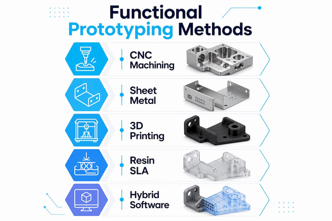
For low-volume manufacturing, consider a hybrid approach: 3D print the form and fit prototype, then machine critical mating surfaces for precision. This keeps iteration fast while hitting tight tolerances where it counts. When evaluating which approach fits your project, finding the best print job for your specific part geometry and material can save significant time.

Also, dimensional accuracy varies by material and color. Black filament consistently delivers the lowest dimensional deviation in FDM, making it the go-to choice when precision is the priority.

Pro Tip: When printing functional FDM parts, use black filament for your validation round. The carbon pigment improves layer adhesion and reduces dimensional error compared to lighter colors.

Detail of black filament for FDM printer

Evaluation, iteration, and scaling for production

With knowledge of preventing and addressing common issues, you’ll want to ensure your parts truly perform and are ready for scaling. Validation is not a single checkpoint. It’s a structured sequence of tests that confirms your prototype meets real-world requirements before you commit to production tooling or larger batch orders.

Testing checkpoints for every prototype:

  • Dimensional check: Measure all critical features with calipers or a CMM (coordinate measuring machine)
  • Mechanical fit: Assemble mating parts and verify clearances, snap-fits, and fastener holes
  • Visual inspection: Check for layer delamination, warping, incomplete infill, or surface defects
  • Functional stress test: Apply expected loads or environmental conditions to confirm performance
  • Material validation: Confirm the prototype material matches production material properties

Empirical data for additive manufacturing provides benchmarks for SLA flexural strength and FDM tensile performance, giving you reference values to compare against your test results.

Prototype stage Typical iteration cycles Primary focus
Concept model 1 to 2 Form and fit
Functional prototype 2 to 4 Fit, function, strength
Pre-production validation 1 to 2 Material match, tolerance

For high-quality prototypes, plan for two to four iteration cycles, with each round using materials that match your intended production process. MJF (Multi Jet Fusion) offers faster cycle times and more isotropic parts than FDM for production-like validation.

When you’re ready to scale, the technology decision matters again. FDM works well for low-volume runs of large, structural parts. SLS and MJF become the better choice for complex geometry, tight tolerances, or batch quantities above 20 to 50 units. Browse real-world prototype examples to see how different technologies perform across part types.

For on-demand print solutions, understanding what can be printed across different technologies helps you plan your scaling path before committing to a production process.

The real challenges and opportunities in step-by-step 3D printing

Here’s what most guides won’t tell you: the engineers who get the best results from 3D printing are not the ones chasing the latest printer or fastest technology. They’re the ones who treat every failed print as a data point, not a setback.

Perfecting your CAD design and printer setup consistently outperforms any speed or technology upgrade. A well-designed part on a mid-range FDM printer beats a poorly designed part on a high-end SLA machine every time. The discipline of iteration, reviewing failures, adjusting one variable at a time, and documenting results, is what separates engineers who scale successfully from those who stay stuck in the prototype loop.

Cross-disciplinary thinking matters here too. Understanding how your end-use environment affects material choice, how your manufacturing process influences design constraints, and how your testing protocol connects to real-world loads gives you leverage that no slicer setting can replicate. Review rapid prototyping realities to ground your workflow in practical expectations. The counter-intuitive truth is that your worst prints, the ones that delaminated, warped, or failed fit checks, are your most valuable teachers if you analyze them systematically.

Get expert support for your 3D printing projects

If you’re ready to push your prototype to the next level but want to reduce guesswork and risk, professional support is one click away. At CC 3D Labs, we handle every stage of the process, from design optimization and material selection to finished functional parts with tight tolerances.

https://cc3dlabs.com

Our team works directly with product developers and engineers to minimize print failures, accelerate iteration cycles, and match your prototype to production-grade requirements. Whether you need a single concept model or a batch of functional parts, our professional 3D printing services are built for your workflow. Explore on-demand prototypes to get started, or review our printing terminology guide to align your project specs before reaching out.

Frequently asked questions

What are the most common 3D printing mistakes and how can I avoid them?

Typical print failures include undersized holes, inadequate clearances, thin walls, and Z-axis weakness from layer anisotropy. Review your CAD file against FDM design rules and always run a test coupon before committing to a full prototype.

How do I pick the right 3D printing technology for my prototype?

Base your choice on required precision, mechanical strength, and batch size. FDM, SLA, SLS, and MJF each occupy different positions on the cost, accuracy, and throughput spectrum, so match the technology to your current validation stage.

How many iterations does a high-quality prototype require?

Most prototypes reach production readiness after two to four iterations, with each round using materials and processes that closely match the intended production method.

What is the advantage of using black filament for FDM prints?

Black filament consistently shows the lowest dimensional deviation in FDM printing, making it the most reliable color choice for parts where precision and tight tolerances are critical.

Engineer checks filament tolerance with calipers

Custom filament printing guide: precision for prototypes


TL;DR:

  • Filament diameter tolerance of ±0.02mm ensures consistent, professional-grade 3D printing results.
  • Proper material choice, printer calibration, and controlled environment are crucial for accuracy and repeatability.
  • Systematic verification and measurement across batches prevent variability and enhance manufacturing reliability.

Even a 0.05mm variation in filament diameter can push a prototype over tolerance, trigger failed prints, and delay your product launch by days or weeks. For product developers and small manufacturing teams, that is not a minor inconvenience. It is a real business cost. ±0.02mm filament tolerance is the benchmark separating consistent, professional-grade output from frustrating batch failures. This guide walks you through every stage of custom filament printing, from material selection and printer setup to parameter tuning and quality verification, so you can produce parts that hold tolerance and hold up under real-world conditions.

Table of Contents

Key Takeaways

Point Details
Choose the right filament Proper filament type and tolerance are the foundation for consistent, successful prints for prototypes and production.
Calibrate and control environment Printer calibration and environmental controls are just as critical as material choice for avoiding common failures.
Optimize print parameters Fine-tuning orientation and slicer settings can dramatically boost part strength and accuracy.
Verify print quality Regular, measured quality checks catch inconsistencies early, ensuring confidence in every print run.
Expert help accelerates results Partnering with a specialized 3D printing service speeds up learning, minimizes costly mistakes, and delivers reliable prototypes.

Understand filament types and requirements

Choosing the right filament is not just about matching color to your brand palette. Material selection determines whether your functional prototype survives a stress test, fits into an assembly, or ships with consistent surface quality across a batch. Getting this decision right upfront saves you rework time and material cost.

Core filament types and where they fit:

  • PLA: Easy to print, dimensionally stable, ideal for concept models and display prototypes. Not suited for heat or mechanical stress.
  • PETG: Balances strength and printability. Great for functional parts, but it is hygroscopic and requires drying before use to avoid bubbles and stringing.
  • ABS: Tough and heat-resistant, essential for functional housings and mechanical parts. Needs an enclosure to prevent warping.
  • Nylon: High impact resistance and flexibility, but absorbs moisture aggressively. Drying is non-negotiable.
  • Carbon fiber, glow-in-the-dark, and metal-filled filaments: Abrasive composites that demand hardened steel nozzles, or you will wear through a standard brass nozzle within hours.
Filament Enclosure needed Drying required Nozzle type
PLA No Rarely Brass
PETG Optional Yes Brass or hardened
ABS Yes Rarely Brass
Nylon Yes Yes Hardened steel
Carbon fiber Yes Yes Hardened steel

Tolerance matters more than most developers realize. A filament rated at ±0.02mm produces under 1% volumetric variation, keeping flow rates consistent across long print runs. Once you step down to ±0.05mm, you are looking at nearly 3% volumetric swing, which shows up as over-extrusion on some layers and under-extrusion on others. You can find more material-specific advice in our prototyping filament guide or dig into a side-by-side breakdown with PLA vs PETG vs ABS.

Color additives also affect printability. Dark pigments, particularly black, absorb more heat and may require a slightly lower temperature than a natural or white version of the same material. Always run a temperature tower when switching colorways on a critical production run.

Pro Tip: Store all hygroscopic filaments in sealed containers with silica gel desiccant between print sessions. Even a few hours of open-air exposure in a humid environment can ruin a spool of Nylon or PETG.

Set up your printer for custom filament printing

Once your material is chosen, your printer and workspace need matching attention. A well-selected filament will still produce poor results if the hardware delivering it is out of calibration or operating in an uncontrolled environment.

Start with these setup steps in order:

  1. Level the print bed. A bed that is even 0.1mm off across its surface will cause adhesion failures on the first layer, which cascades into every layer above it.
  2. Clean the hot end. Residual material from a previous filament run causes contamination, especially when switching from a high-temperature material to a lower-temperature one.
  3. Check the extruder tension. Too tight and you grind the filament. Too loose and steps are skipped. Both cause inconsistent flow.
  4. Calibrate your extruder steps per mm. Mark 100mm of filament, extrude it, and measure what actually moved. Adjust until the numbers match.
  5. Set nozzle diameter to match your job. Abrasive filaments require a hardened nozzle. Standard brass erodes fast under carbon fiber or metal-filled materials.

Environment matters too. ±0.05mm diameter variation creates a 2.8% volumetric swing that no software setting can fully compensate for, but ambient temperature swings make things worse. ABS requires a fully enclosed printer to maintain a consistent chamber temperature and prevent warping from drafts. Hygroscopic materials need controlled humidity both in storage and during printing.

A stable printer in a controlled workspace produces more consistent results than a high-end machine sitting in a drafty, humid shop floor. Environment is not optional.

Printer check What to look for Tool needed
Bed level Even first layer adhesion Feeler gauge or probe
Extruder calibration 100mm extrusion accuracy Ruler or calipers
Hot end cleanliness No residue or discoloration Cold pull or cleaning filament
Nozzle condition No erosion on tip Visual inspection

For batch production specifically, you will want to build a pre-run checklist. Our low-volume manufacturing tips walk through setup routines designed to keep quality consistent across dozens of parts. If you are deciding between printer types for your workflow, choosing the right printing type covers that decision in detail.

Pro Tip: Run a small calibration cube before every new filament spool or environmental change. It takes five minutes and tells you immediately if something has drifted.

Woman calibrates 3D printer for new filament

Optimize print parameters for strength and accuracy

Once hardware is ready, fine-tuning print parameters maximizes your results. Slicer settings are where most developers either gain or lose the edge on part performance.

Orientation is the most underestimated variable in filament printing. FDM parts are anisotropic, meaning they are stronger along the layer plane than perpendicular to it. Placing a part so its primary load axis runs parallel to the print bed increases stiffness dramatically. Parameter optimization, including orientation and layer height adjustments, has been shown to boost part stiffness by 81 to 128%. That is not a marginal gain. It is the difference between a prototype that passes mechanical testing and one that snaps during the first use cycle.

Follow this sequence when dialing in parameters for a new job:

  1. Set orientation first. Analyze load direction and place the strongest axis in line with expected stress.
  2. Choose layer height. Thinner layers (0.1mm to 0.15mm) improve surface detail and interlayer bonding for functional parts. Thicker layers (0.2mm to 0.3mm) speed up prototyping when detail is less critical.
  3. Tune temperature. Advanced materials like PETG and Nylon run hotter and benefit from a temperature tower to find the sweet spot for flow and layer adhesion without stringing.
  4. Set print speed. Slower speeds improve accuracy. For precision prototypes, drop below 40mm/s on perimeters.
  5. Adjust cooling. PLA needs active cooling. ABS and Nylon need minimal or no cooling to prevent layer delamination.

Black filaments deserve a specific note. Because of their higher heat absorption, black variants of the same base material often need a temperature reduction of 5°C to 10°C compared to neutral colors. Skipping this step leads to over-melting and oozing on fine features.

For guidance on building print-ready geometry that supports these parameters, our resource on designing reliable prints and optimizing your CAD workflow are worth your time before you hit slice.

Pro Tip: Never rely on a slicer’s default profile for a production run. Always run a first-article part with your specific filament, nozzle, and environment before committing to a full batch.

Quality verification and troubleshooting

With parameters optimized, assess and fix your results for business-grade consistency. Printing one good part is not the goal. Printing forty identical good parts is.

Start with visual inspection on every part:

  • Layer lines: Should be uniform in height and spacing. Inconsistent lines point to extruder slippage or filament diameter variation.
  • Wall smoothness: Rough or pitted walls signal moisture in the filament or a clogged nozzle.
  • Color consistency: Streaks or shade shifts mid-print indicate contamination or temperature instability.

After visual checks, measure. Use calipers to verify critical dimensions against your CAD model. Tolerance variations at ±0.02mm create under 1% dimensional error, while ±0.05mm filament pushes that beyond 2.8%. For parts going into assemblies, even 0.1mm of deviation can mean a misfit. Document your measurements across each batch so you can track drift over time.

Iteration is not failure. Running three calibration parts before a 50-piece batch is a quality investment, not wasted material.

Common error Symptom Solution
Under-extrusion Thin walls, gaps in layers Increase flow rate, check extruder tension
Over-extrusion Blobbing, rough surfaces Reduce flow rate or temperature
Warping Lifted corners Use enclosure, increase bed adhesion
Stringing Fine threads between features Increase retraction, reduce temperature
Layer delamination Cracks between layers Increase temperature, reduce cooling

Infographic with filament troubleshooting and solutions

For visual references of what precision output actually looks like at each stage, our prototype quality examples show real parts printed to specification.

Why most guides miss what actually matters in custom filament printing

Most online guides focus on slicer profiles and temperature charts. Those things matter, but they are not the ceiling. The real ceiling for manufacturing reliability is filament consistency and systematic verification across batches.

Here is what experience teaches you: even a premium slicer profile running on a well-calibrated machine cannot compensate for a filament spool with inconsistent diameter. If the material feeding into your nozzle varies by 0.05mm or more throughout the spool, your flow rate fluctuates regardless of your settings. You can tune all day and still see surface variation on parts 20 and 40 that looked fine on parts 1 and 2.

The second thing most guides skip is the difference between a successful single print and a repeatable process. For a product developer or small manufacturer, repeatability is everything. One good prototype means little if your next run of 30 parts has visible variation. Build a verification step into every run. Measure early, measure often, and document what you find. That process discipline is what separates hobbyist output from professional manufacturing output.

Our additional prototyping strategies go deeper into building that kind of repeatable workflow.

Take your custom filament printing further with CC3DLabs

If you are hitting the limits of what in-house printing can deliver for precision, batch consistency, or advanced materials, working with an experienced team changes the equation.

https://cc3dlabs.com

At CC3D Labs, near Philadelphia, we specialize in custom filament-based 3D printing for product developers and manufacturing teams who need parts that perform, not just parts that look right on a screen. Our 3D printing services cover everything from single prototypes to production runs, with material expertise and quality verification built into every job. Want to know what is possible before you commit? See our printing capabilities and browse real-world prototype case studies to see the standard we hold our work to. Reach out for a free estimate and let us help you get it right the first time.

Frequently asked questions

What is the ideal filament tolerance for precision 3D printing?

A filament diameter tolerance of ±0.02mm delivers the best print consistency for prototypes and low-volume manufacturing, keeping volumetric variation under 1%.

Why do some filaments require drying before printing?

Hygroscopic filaments like PETG and Nylon absorb moisture from the air, which causes bubbling, poor layer adhesion, and stringing unless the material is thoroughly dried before printing.

How does orientation impact 3D printed part strength?

Optimizing part orientation during slicing aligns the strongest axis with the load direction, with research showing stiffness improvements of up to 128% compared to default orientations.

How do you check if your print is accurate?

Measure critical dimensions with calipers and compare them to your CAD model. Tolerance variations above ±0.05mm can push dimensional error past 2.8%, which is unacceptable for assembly-fit parts.

Designer reviewing online 3D printing estimate

Get precise online estimates for custom 3D printing


TL;DR:

  • Online quoting speeds up 3D printing workflows and helps with rapid design decisions.
  • Automated estimates are generally accurate for standard geometries but less reliable for complex features.
  • Preparing models carefully and validating quotes with manual reviews can improve cost accuracy and project success.

Waiting three days for a quote when your prototype deadline is tomorrow is not a workflow problem. It’s a competitive disadvantage. Traditional manual quoting slows engineering cycles, creates budget uncertainty, and forces developers to guess at costs during the most critical design phases. Instant quoting systems automate pricing by analyzing uploaded STL files, material choices, print time, and part complexity in seconds. But speed comes with trade-offs. This guide breaks down how online estimates work, where they fall short, and the practical strategies you can use to get numbers you can actually build a budget around.

Table of Contents

Key Takeaways

Point Details
Speed boosts workflow Instant online estimates slash prototyping delays and empower rapid engineering iteration.
Check itemized costs Always review the detailed breakdown—material, machine, labor, post-processing—for transparency and accuracy.
Know quoting limits Complex geometries and post-processing often require manual review, so buffer for hidden costs.
Design for accuracy Optimizing designs for quoting—minimizing supports and overhangs—produces more reliable instant estimates.
Benchmark for best value Compare multiple quoting platforms and ask for engineer reviews to ensure cost and quality alignment.

How online estimates transform 3D printing workflows

An online estimate, sometimes called an instant quote, is an automated pricing system that reads your 3D model file and returns a cost breakdown without human intervention. You upload a file, select a material and finish, and the platform calculates price based on volume, geometry, and machine parameters. The result arrives in seconds rather than days.

For product developers and engineers, this changes everything about early-stage design. You can test five material options in five minutes. You can compare a solid infill against a lightweight lattice structure and see the price difference immediately. Online estimators accelerate prototyping by providing immediate feedback on design changes, material trades, and quantity discounts. That feedback loop is what makes iterative design actually fast.

Infographic showing 3D print online quote process

Manual quoting, by contrast, typically takes 24 to 72 hours per request. For a team running ten design iterations per week, that delay compounds fast. Shapeways instant quoting platforms have demonstrated that automated systems can reduce quote turnaround from days to under a minute for standard geometries. That is not a marginal improvement. It is a fundamentally different workflow.

Here are the most common use cases where online estimates deliver real value:

  • Rapid prototyping: Get cost feedback before committing to a design revision
  • Material comparison: Instantly compare PLA, PETG, ABS, and nylon pricing for the same geometry
  • Functional part production: Estimate unit economics for small batch runs before scaling
  • Design iteration: Adjust wall thickness, infill, or orientation and see cost impact in real time
  • Budget planning: Establish rough cost ranges early in the product development cycle

Pairing this speed with a solid optimizing CAD workflow process means your files are quote-ready before you even hit submit. The engineers who get the most out of instant quoting are the ones who treat file preparation as part of the design process, not an afterthought.

Demystifying 3D printing cost calculation: What’s in an online quote?

Most engineers treat the quote number as a black box. Understanding what’s inside it gives you real leverage. STL file parsing for volume, surface area, and bounding box forms the foundation of every automated estimate. From there, the system estimates print time using slicing simulation or heuristics, then applies a cost formula.

The standard formula looks like this: Material cost (weight × $/g) + Machine cost (hourly rate × print time) + Labor + Overhead + Markup. Each variable carries its own uncertainty. Material weight depends on infill density. Machine time depends on layer height and print speed. Labor and overhead vary by provider.

Engineer calculating 3D printing quote by hand

Here is a simplified example of how those components stack up for a mid-complexity functional bracket:

Cost component Basis Example amount
Material 45g × $0.08/g $3.60
Machine time 2.5 hrs × $4.00/hr $10.00
Labor Setup and removal $5.00
Overhead Facility, utilities $3.00
Markup 30% $6.48
Total estimate $28.08

The quoting sequence for a custom part typically follows these steps:

  1. Upload STL file to the platform
  2. System parses geometry for volume, surface area, and bounding box
  3. Slicer simulation estimates print time and material usage
  4. Cost formula applies material, machine, labor, and overhead rates
  5. Markup is added and the estimate is returned to the user
  6. Optional: engineer review for flagged complex geometries

For a deeper look at how these numbers are assembled, the cost calculator guide breaks down the math behind each variable. Understanding itemized quoting breakdowns also helps you spot when a platform is bundling costs that should be line items.

Pro Tip: Always request an itemized cost breakdown rather than a single total. If a platform only shows you one number, ask for a manual review on any prototype that has thin walls, internal channels, or significant overhangs. Those features are where automated estimates lose accuracy fast.

Recognizing the limits: When online quotes fall short

Instant quoting is powerful, but it has a ceiling. Complex geometries can fail automated analysis entirely. Thin walls below 1.2mm, extreme overhangs, and internal lattice structures push most quoting algorithms into uncertain territory. The system either flags the file for manual review or, worse, returns a price that does not reflect the actual print difficulty.

Post-processing is the biggest blind spot. Post-processing costs can increase final invoices by 30 to 40 percent, and most instant quoting systems do not model this accurately. Support removal, sanding, painting, and inspection are labor-intensive steps that vary by part geometry in ways that are hard to automate.

Here is a quick comparison of instant quoting versus manual engineering review:

Factor Instant online quote Manual engineering review
Speed Seconds to minutes 24 to 72 hours
Transparency Variable High
Accuracy (standard parts) Good Excellent
Accuracy (complex parts) Poor to moderate Excellent
Post-processing included Rarely Usually
Cost Free or low May carry a fee

Common hidden costs that online estimates frequently miss include:

  • Support structure material and removal labor
  • Surface finishing (sanding, priming, painting)
  • Dimensional inspection and quality documentation
  • Failed print reprints (especially for complex geometries)
  • Expedited turnaround fees

For tips for accurate instant quoting on complex parts, the key is knowing when to escalate. If your part has features that would give a human engineer pause, an automated system will not catch them reliably. Reviewing instant quoting system alternatives can also reveal platforms with more robust manual review pipelines built into their workflows.

The cost drivers in 3D print quotes are more nuanced than most automated systems capture, particularly when functional performance requirements enter the picture.

How to get accurate online estimates: Practical engineering strategies

Getting a reliable estimate is not just about picking the right platform. It is about preparing your model and your process so the automated system has everything it needs to return a meaningful number.

Here are the key steps for reliable instant quoting:

  • Optimize your model first: Clean up non-manifold geometry, remove duplicate surfaces, and confirm wall thickness meets minimum print requirements before uploading
  • Select platforms with itemized breakdowns: Prioritize platforms with itemized breakdowns and engineer review options, especially for prototypes and functional parts
  • Request manual review for edge cases: If your part has overhangs greater than 45 degrees, thin walls, or complex internal geometry, flag it for human review
  • Compare multiple estimators: Run the same file through two or three platforms and compare results. Significant variance signals a part that needs manual attention
  • Use benchmark quoting calculators to cross-check: Independent calculators help you validate whether a platform’s estimate is in a reasonable range

Pro Tip: For prototypes, orient your model to minimize support structures before uploading. A part printed at a 45-degree angle often uses significantly less support material than one printed flat, and that directly reduces both material cost and post-processing labor. Small orientation decisions at the design stage translate into real savings in the estimate.

For functional parts, always benchmark your online quote against a manual review before committing to a production run. The CAD estimate form at CC 3D Labs allows you to submit files for review with specific functional requirements noted, which gives our team the context to catch cost variables an automated system would miss.

Also review quoting platform comparisons to understand which services offer the transparency and engineering support your project actually requires. Not all platforms are built for the same use cases, and choosing the wrong one for a functional part run can cost you more than the time you saved on quoting.

The engineering reality: Instant quotes vs. true costs

Here is something most online quoting platforms will not tell you: the number on your screen is a starting point, not a contract. We have seen engineers treat instant estimates as final budgets, only to face invoices that are 30 to 40 percent higher once post-processing and quality checks are factored in.

The math behind this is straightforward. Material is only 15 to 30% of total print cost. Machine time, labor, and failure rates (typically 5 to 10 percent for complex geometries) dominate the actual invoice. Instant quoting systems are optimized to calculate material and machine time accurately. They are not optimized for the human labor that happens after the print finishes.

The race-to-the-bottom pricing you see on some platforms is a red flag, not a deal. Providers who compete purely on quote price often cut corners on material quality, machine calibration, or post-processing thoroughness. For a display model, that might be acceptable. For a functional part that goes into a product, it is a liability.

Our recommendation for low-volume manufacturing tips is to always buffer your budget by at least 20 percent above the online estimate for functional part runs. For complex prototypes, budget for at least one reprint. Use the instant quote as a directional signal, then validate it with a manual review before finalizing your project budget. The engineers who do this consistently are the ones who hit their timelines without budget surprises. See how custom print job selection factors into getting the right service match for your specific application.

Level up your 3D printing workflow with trusted solutions

Applying these strategies is straightforward when you have a service provider who builds transparency into every quote. At CC 3D Labs, we offer both instant online estimates and detailed manual reviews for complex prototypes and functional parts.

https://cc3dlabs.com

Our 3D printing services are designed for product developers and engineers who need accurate numbers, not ballpark figures. Whether you are exploring printing prototypes and functional parts for the first time or managing a batch production run, our team provides itemized breakdowns that reflect real costs. Request a custom print quote today and see the difference that engineering-backed quoting makes for your project timeline and budget.

Frequently asked questions

How accurate are online estimates for 3D printing?

Online estimates are typically reliable for standard geometries but often underrepresent total costs for complex features or finishing work. Post-processing costs can increase final invoices by 30 to 40 percent above the initial automated quote.

What file formats are best for automated online quoting?

STL files are the standard for 3D print quotes because they provide the volume and geometry data needed for automated cost calculation. Parsing STL files for volume, surface area, and bounding box is the foundation of every instant quoting system.

Can online estimates factor in quantity discounts?

Yes, many instant quoting platforms adjust pricing automatically based on order quantity. Immediate feedback on quantity discounts is one of the strongest advantages of automated estimators for batch prototype planning.

How can I make my model easier to quote instantly?

Simplify your geometry by minimizing overhangs and support-heavy features, and choose an orientation that reduces material usage before uploading. Minimizing supports and overhangs early in the design process produces more reliable automated estimates and lower actual print costs.