Artist sketching custom wedding 3D print design

Custom Wedding 3D Prints: 10 Inspiring Examples


TL;DR:

  • Custom wedding 3D prints offer personalized, functional objects like cake toppers, centerpieces, and keepsakes that enhance wedding decor. Using AI and professional services, couples can create detailed, durable items at a lower cost and within short timeframes, ensuring meaningful personalization. Strategic planning and choosing appropriate printing methods—resin for detail and FDM for larger decor—maximize value and long-term relevance of these customized pieces.

Custom wedding 3D prints are personalized three-dimensional objects designed and produced specifically for weddings, covering everything from cake toppers to centerpieces and keepsake gifts. The industry term for these objects is “custom additive manufacturing for events,” though most couples and vendors simply call them personalized wedding 3D prints. Tools like Sloyd AI now generate printable STL files from photos in seconds, and platforms like Cults3D host hundreds of ready-to-customize wedding models. Whether you want a figurine that looks exactly like you and your partner or a functional money holder for the reception table, the examples of custom wedding 3D prints available today are more varied and affordable than most couples realize.

1. Examples of custom wedding 3D prints: romantic couple cake toppers

Romantic couple figurines are the most requested category of customized wedding cake toppers, and for good reason. AI tools like Sloyd AI can generate a printable STL file from a couple’s photos in seconds, removing the need for any design skills. The result is a topper that captures specific hairstyles, clothing silhouettes, and poses that no mass-produced product can replicate.

  • Flowing bridal gown details and stable bases are standard features on popular resin-printed toppers, making them display-ready after printing
  • Classic romantic poses without visual clutter improve the keepsake value long after the wedding day
  • Resin printing captures the fine surface detail that FDM filament printing cannot match at this scale

Printing a topper typically takes 2 to 6 hours depending on complexity, and filament material costs run under $5. That figure covers only the raw material. The model file and any professional finishing add to the total, but the overall cost still undercuts most custom ceramic or porcelain alternatives.

Pro Tip: Order a test print at least three weeks before the wedding. Resin prints can warp slightly during post-cure if the ambient temperature is inconsistent, and you want time to reprint if needed.

Detailed 3D printed romantic couple cake topper

2. Minimalist cake toppers for modern weddings

Minimalist designs with clean silhouettes and stable bases are preferred by digital sculptors for their timeless compatibility with nearly any wedding aesthetic. A simple two-figure silhouette in matte white PLA reads as elegant on a rustic barn cake and equally well on a sleek modern tiered cake. This style also prints faster and with fewer support structures, which reduces both cost and post-processing time.

The practical advantage of minimalism goes beyond aesthetics. Fewer overhangs mean fewer potential print failures, which matters when you are working against a wedding deadline. Couples who want personalization without the complexity of a fully detailed figurine find that a monogram base or a custom name plate beneath a clean silhouette delivers the same emotional impact at a fraction of the modeling cost.

3. Creative 3D printed wedding centerpieces and décor

Wedding decor 3D printing produces items that serve double duty: they look beautiful on the table and remain useful after the event. The most popular examples include:

  1. Geometric vases printed in PLA or PETG that hold fresh or dried floral arrangements
  2. Custom table number holders with the couple’s monogram or a motif that matches the invitation suite
  3. Money gift holders shaped like hearts or infinity symbols that guests interact with during the reception
  4. Photo frame centerpieces designed to hold a couple photo and a small flower pod in one unified structure

Functional pieces like money holders and photo frames increase emotional and practical value well beyond the wedding day. A guest who takes home a table number holder as a favor gets a functional object, not just a memento. This is the key difference between generic wedding decor and pieces designed with post-event life in mind.

For budgeting, DIY printing on a home FDM printer keeps per-unit costs low but requires time and skill. Professional services like Cc3dlabs handle multi-color and multi-material runs that a home printer cannot replicate, which is worth the added cost for centerpieces that need to photograph well. You can also explore laser-cut wood alternatives to complement your 3D printed pieces for a mixed-material table design.

4. Personalized 3D printed wedding gifts and keepsakes

Custom 3D figurines sized between 5 and 15 centimeters are the most requested unique 3D printed wedding gifts, used as both ceremony decor and lasting keepsakes. Services like Art Mellow require couples to submit photos for artist review before printing begins, with the final piece including painting and assembly. The minimum print size for adequate facial and clothing detail is 15 centimeters.

Pricing for these pieces is driven primarily by digital sculpting labor, not physical size. The modeling effort is roughly equal whether the final print is 5 or 15 centimeters tall, which means you get better value by ordering at the larger size. Multi-color prints add another layer of realism. A figurine with skin tones, hair color, and fabric texture printed in separate materials reads as a portrait, not a toy.

  • Post-processing steps like sanding, priming, and painting are what separate a display-quality keepsake from a raw print
  • Multi-color photo frames that hold a couple photo and a small floral arrangement combine romantic design with everyday function
  • Keepsake holders, ring dishes, and personalized jewelry boxes are lower-complexity prints that still carry strong sentimental value

Pro Tip: If you use an AI-generated model for a figurine, run it through mesh repair software like Meshmixer or PrusaSlicer’s built-in repair tool before sending it to print. AI-generated models often have hidden geometry issues that cause print failures mid-job.

5. Choosing the right printing method and materials

The choice between resin and FDM filament printing determines the final quality of your wedding items more than any other single decision. Here is a direct comparison:

Feature Resin printing FDM filament printing
Surface detail High. Best for figurines and toppers Moderate. Visible layer lines at small scales
Cost per print Higher material and equipment cost Lower. Under $5 in filament for most items
Print time 2 to 4 hours for small figurines 2 to 6 hours depending on infill and size
Best use case Cake toppers, figurines, keepsakes Vases, frames, table numbers, favor boxes
Post-processing Requires UV curing and washing Sanding and priming for smooth finish

Resin printing is recommended for any item between 10 and 20 centimeters tall where surface quality matters. FDM printing in PLA or PETG is the right call for larger decorative items where layer lines are not visible at normal viewing distance. For outdoor wedding decor, material selection becomes critical. PETG and ASA outperform PLA in heat and humidity, which matters for summer ceremonies.

Pro Tip: Request a material sample from your printing service before committing to a full run of favors or centerpieces. Color, sheen, and rigidity vary significantly between PLA brands, and what looks good on screen may not match your wedding palette in person.

6. How to integrate 3D prints into your wedding planning

Timing is the most underestimated factor when ordering personalized wedding 3D prints. Custom figurines that require photo-based digital sculpting need at least four to six weeks from order to delivery. Simpler items like favor boxes or table numbers can be turned around in one to two weeks, but you still need time for review and reprints.

Practical steps for a smooth workflow:

  • Start with a priority list. Identify which items are display-critical (cake topper, centerpiece) versus functional (favor boxes, table numbers) and allocate budget accordingly
  • Mix materials intentionally. 3D printed geometric vases pair well with traditional floral arrangements. The contrast between the precision of a printed object and the organic quality of fresh flowers is visually striking
  • Use AI tools for early concepts. Platforms like Sloyd AI let you generate a rough model quickly so you can evaluate proportions and style before paying for professional sculpting
  • Plan for care and preservation. PLA prints are sensitive to heat above 60 degrees Celsius. Store keepsakes away from direct sunlight and avoid leaving them in a hot car after the reception
  • Work with a service that offers design support. The 3D modeling process for custom wedding items involves file preparation, support structure planning, and material selection. A professional service handles all of this so you focus on the design, not the technical workflow

Combining traditional wedding elements with 3D printed accents creates a layered aesthetic that feels personal without looking like a tech showcase. A hand-calligraphed seating chart next to 3D printed place card holders, for example, blends craft traditions with modern production in a way that photographs beautifully.

Key takeaways

Custom wedding 3D prints deliver the most value when you match the printing method to the item type, order early, and prioritize digital sculpting quality over raw material cost.

Point Details
Resin for detail, FDM for scale Use resin printing for figurines and toppers; use FDM for vases, frames, and favor boxes.
Sculpting labor drives cost For custom figurines, the modeling effort is the main expense regardless of print size.
Order six weeks out Photo-based custom figurines require four to six weeks from submission to delivery.
Functional prints last longer Items like money holders and photo frames retain value and use well beyond the wedding day.
Repair AI models before printing AI-generated STL files often need mesh repair to avoid mid-print failures.

Why 3D printing is changing what weddings look like

I have seen a clear shift over the past few years in how couples approach wedding personalization. The request used to be “can you make something that looks like us?” Now it is “can you make something that is us, functions at the reception, and still looks good on our shelf in ten years?” That is a fundamentally different design brief, and 3D printing is the only production method that can answer all three parts of it at a reasonable cost.

What surprises most couples is how much the design phase matters relative to the print itself. A well-sculpted model printed on a mid-range FDM machine will outperform a poorly designed model printed on a professional resin system every time. The technology is a tool. The design is the product. I always tell couples to spend more of their budget on a skilled modeler and less on chasing the most expensive printing method.

The trend I find most interesting right now is the move toward functional keepsakes. A cake topper that becomes a desk ornament, a centerpiece vase that holds flowers for years after the wedding, a ring dish printed with the wedding date. These objects carry the memory of the day in a way that a photograph cannot, because you interact with them. That is where 3D printing genuinely outperforms every other personalization method available to couples today.

— Justin

Bring your wedding vision to life with Cc3dlabs

Cc3dlabs specializes in custom filament-based 3D printing and CAD modeling near Philadelphia, with the capability to handle everything from single cake toppers to full sets of wedding centerpieces and favors.

https://cc3dlabs.com

Whether you need a photo-based figurine sculpted from scratch, a multi-color photo frame, or a batch of personalized favor boxes, Cc3dlabs offers design support, material selection guidance, and fast turnaround for both local pickup and shipping. You can browse completed wedding and gift projects in the project gallery or go directly to the 3D printing services page to request a free estimate. For couples who want to explore the full range of what is possible, the personalized gift examples page is a strong starting point.

FAQ

The most popular examples are romantic couple cake toppers, geometric centerpiece vases, personalized photo frames, money gift holders, and custom table number stands. Each category can be tailored to a couple’s specific style, color palette, and wedding theme.

How much do custom 3D printed wedding items cost?

Filament material for a single item costs under $5, but the total price depends heavily on whether a custom model needs to be digitally sculpted. Photo-based figurines from professional services cost significantly more because digital sculpting labor is the primary cost driver, not the physical print.

Is resin or FDM printing better for wedding cake toppers?

Resin printing is the better choice for cake toppers and figurines between 10 and 20 centimeters tall because it captures fine surface detail that FDM filament printing cannot reproduce at that scale. FDM is more cost-effective for larger decorative items where surface texture is less critical.

How far in advance should I order custom 3D printed wedding items?

Order photo-based custom figurines at least four to six weeks before the wedding to allow time for sculpting, review, printing, and finishing. Simpler items like favor boxes or table number holders can be completed in one to two weeks.

Can I use AI tools to design my own wedding 3D prints?

Yes. Tools like Sloyd AI generate printable STL files from photos in seconds without any design skills required. AI-generated models often need mesh repair before printing, so run the file through software like Meshmixer or PrusaSlicer before sending it to a printer.
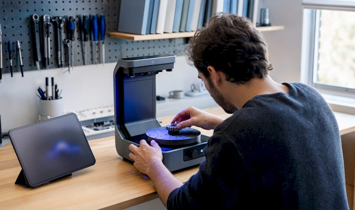

Technician scanning small mechanical part

Types of Objects Suitable for 3D Scanning: 2026 Guide


TL;DR:

  • Object size, surface texture, and material compatibility determine the suitable 3D scanning technology for each project. Small objects benefit from high-resolution structured light or laser scanners, while large structures often require photogrammetry or LiDAR methods. Proper surface preparation and understanding of material properties are essential to achieve accurate, clean digital captures suited to the object’s intended use.

Types of objects suitable for 3D scanning are defined by three core factors: size, surface texture, and material compatibility with the chosen scanning technology. Whether you are a product developer reverse engineering a mechanical part, an artist digitizing a sculpture, or a manufacturer capturing a prototype for quality control, the object itself determines which scanner you need and how you prepare for the job. Methods like photogrammetry, structured light scanning, and laser scanning each perform differently depending on what sits in front of them. Getting that match right from the start eliminates rework and produces cleaner data.

1. Types of objects suitable for 3D scanning: small and medium items

Small and medium objects represent the most common category scanned for prototyping, dental applications, and jewelry design. Items like rings, crowns, miniature figurines, and small mechanical components all fall here. Resolution matters more than raw accuracy at this scale. A scanner that captures 0.01mm surface detail will reveal geometry that a general-purpose device misses entirely.

Surface preparation is the deciding factor for scan quality on small objects. Metallic jewelry and polished prototypes reflect light back at the scanner, creating noise and holes in the mesh. Applying a thin layer of AESUB Blue vanishing spray allows structured light scanners to capture high-detail geometry without permanently altering the object. The spray evaporates on its own within hours, leaving no residue.

  • Jewelry and rings: Require blue structured light or laser scanning due to metallic reflectivity
  • Dental models: Demand sub-0.05mm accuracy; turntable setups with automated rotation are standard
  • Small prototypes and mechanical parts: Benefit from handheld or desktop structured light scanners
  • Figurines and collectibles: Photogrammetry works well when surface texture is matte and detailed

Pro Tip: Automated turntables improve consistency for small objects by minimizing stitching gaps and delivering uniform angular coverage. For dental models and jewelry, this repeatability is not optional. It is the difference between a usable scan and a session you repeat three times.

2. Large and architectural objects: challenges and approaches

Close-up of turntable scanning setup for small object

Large objects like buildings, vehicles, aircraft fuselages, and industrial equipment present a different set of constraints. You cannot place a building on a turntable. The scanner must come to the object, and the data volume grows exponentially with scale. Photogrammetry scales effectively with camera placement, making it the dominant method for structures where sub-millimeter precision is not the primary goal.

When precision does matter at large scale, pulse-based and phase shift technologies take over. Long-range 3D scanners using these technologies are specifically engineered for buildings, military vehicles, and industrial equipment. Phase shift scanners offer faster data acquisition at medium range, while pulse-based systems reach farther with slightly lower point density.

Object type Recommended technology Key consideration
Buildings and facades Photogrammetry or LiDAR Environmental lighting control
Vehicles and aircraft Phase shift or handheld laser Access to undercarriage and interior
Industrial equipment Pulse-based long-range scanner Scale and occlusion management
Large sculptures Photogrammetry Texture richness aids reconstruction

Environmental control is the hidden challenge at large scale. Wind, changing sunlight, and vibration all degrade scan quality. Scheduling outdoor scans during overcast conditions reduces harsh shadows that distort mesh reconstruction. For interior architectural scans, turning off fluorescent lighting and using the scanner’s own projected pattern eliminates competing light sources.

3. Surface materials and textures: how composition affects scan quality

Surface material is the single most disruptive variable in 3D scanning. Reflective, transparent, and very dark surfaces all defeat standard scanning methods in different ways. A chrome-plated part scatters structured light unpredictably. A glass bottle transmits the scanner’s projected pattern rather than reflecting it. A matte black rubber gasket absorbs light and returns almost no signal.

Blue laser technology is the preferred solution for dark or reflective metal surfaces, while infrared technology is favored for scanning human subjects due to comfort and reduced light sensitivity. This distinction matters practically. Scanning a polished stainless steel bracket requires a different scanner than scanning a foam prototype or a human face.

  • Reflective metals: Use blue laser scanning or apply AESUB vanishing spray before structured light capture
  • Transparent objects: Apply matte spray or painter’s tape to create a scannable surface layer
  • Dark rubber or foam: Blue laser or high-sensitivity structured light; increase exposure settings
  • Matte plastics and ceramics: Compatible with nearly all scanning methods; photogrammetry works well

Matte sprays and painter’s tape are standard workarounds for glossy or transparent surfaces. Painter’s tape applied to a glass object creates a textured, opaque surface the scanner can read. The tape is removed after scanning, and the geometry underneath is reconstructed from the captured shell. It is a low-cost fix that saves hours of post-processing.

Pro Tip: Before committing to a full scan session on a difficult material, test on a proxy object with similar surface properties. A chrome-plated test piece from a hardware store costs almost nothing and tells you exactly how your scanner responds before you risk a client’s irreplaceable part.

4. Functional and artistic applications: objects scanned for prototyping and design

The intended end-use of a scan determines how much accuracy and detail you actually need. A museum-grade archival scan of a Roman coin requires maximum fidelity and color accuracy. A game-ready asset of the same coin needs optimized topology and a fraction of the polygon count. Different applications require varying accuracy levels, from high-poly archival masters to low-poly performance-optimized models.

Here is how object types map to their primary scanning applications:

  1. Mechanical parts for reverse engineering: Require dimensional accuracy within 0.02mm or better; structured light or industrial laser scanning is standard
  2. Product prototypes: Scanned to verify geometry against CAD files; design accuracy is the primary metric
  3. Sculptures and fine art: Photogrammetry captures color and texture simultaneously; hybrid workflows add structured light for precise geometry
  4. Cultural artifacts and museum pieces: Hybrid workflows combining photogrammetry for texture and structured light for geometry produce archival-grade digital twins
  5. Human subjects for medical or fashion use: Infrared structured light scanning; fast capture minimizes subject movement artifacts
  6. Architectural elements for renovation: Photogrammetry or LiDAR; outputs feed directly into BIM software like Autodesk Revit

The connection between end-use and scan specification is direct. Scanning a prototype for a manufacturing quality check demands tighter tolerances than scanning the same part for a marketing render. Defining the output requirement before you scan prevents over-engineering the capture process and saves time in post-processing.

5. Comparing scanning methods by object type and material

Choosing the right scanning method is not about buying the most expensive hardware. Analyzing object size, surface qualities, and intended use before attempting a scan reduces rework and produces better outcomes. The table below maps the four primary technologies to their strongest use cases.

Scanning method Best object types Strengths Limitations
Photogrammetry Large textured objects, sculptures, buildings Low cost, scalable, captures color Struggles with featureless or shiny surfaces
Structured light Small to medium parts, dental, jewelry High resolution, fast capture Limited range; sensitive to ambient light
Laser scanning Reflective metals, industrial parts Works on dark and shiny surfaces Higher cost; slower than structured light
LiDAR Buildings, outdoor environments, vehicles Long range, fast point cloud Lower resolution for fine surface detail

Photogrammetry excels on large textured objects while structured light and laser scanning outperform it on smaller metallic and reflective surfaces. This is not a hierarchy. It is a tool-to-task match. A $500 photogrammetry setup with a DSLR and Meshroom software can outperform a $10,000 structured light scanner when the object is a textured stone wall. The reverse is equally true for a polished aluminum housing.

Handheld scanners offer flexibility for irregular shapes, while turntable scanners provide repeatability and speed for small, manageable objects. For professionals running high-volume scanning workflows, the turntable approach reduces per-scan time significantly and standardizes output quality across batches.

Key takeaways

Matching object size, surface material, and intended use to the correct scanning technology is the single most important decision in any 3D scanning project.

Point Details
Size determines scanner type Small objects need high-resolution desktop or turntable setups; large objects require photogrammetry or long-range LiDAR.
Surface material drives technology choice Reflective and transparent surfaces require blue laser scanning or surface preparation with matte spray before capture.
End-use defines required accuracy Archival and reverse engineering scans demand tight tolerances; artistic or game-ready assets prioritize optimized geometry.
Preparation prevents rework Testing on proxy objects and controlling lighting conditions before the final scan eliminates the most common failure points.
Hybrid workflows solve complex objects Combining photogrammetry for texture with structured light for geometry captures both color and precision in one pipeline.

What I have learned from scanning hundreds of objects

The most expensive mistake I see professionals make is selecting a scanner based on brand reputation rather than object characteristics. A high-end structured light scanner is the wrong tool for a textured sandstone facade, no matter how good the spec sheet looks. The object tells you what it needs. Your job is to listen.

Surface preparation is where most scans are won or lost before the scanner even turns on. I have watched teams spend hours in post-processing trying to fill holes that a two-minute matte spray application would have prevented entirely. The 3D scanning checklist approach, where you assess material, size, and lighting before touching the hardware, consistently produces cleaner first-pass data than any amount of software correction afterward.

The other insight that took me time to internalize: photogrammetry is not a budget compromise. For large, richly textured objects, it is genuinely the best tool available. A controlled photogrammetry session with a calibrated camera and diffuse lighting will outperform a rushed laser scan on a building facade every time. The misconception that quality scans require expensive hardware persists because people conflate cost with capability. They are not the same thing.

— Justin

Bring your objects to life with Cc3dlabs

Whether you are scanning a precision mechanical part, a one-of-a-kind sculpture, or a batch of product prototypes, the quality of your scan determines everything that follows.

https://cc3dlabs.com

Cc3dlabs offers metrology-grade 3D scanning services near Philadelphia, covering a full range of object types from small jewelry and dental models to large industrial components. The team handles surface preparation, technology selection, and post-processing so your data arrives clean and ready for CAD modeling, printing, or archival. If you are ready to move from physical object to precise digital model, Cc3dlabs provides the expertise and equipment to do it right the first time. Explore the full range of printing and scanning services or request a free estimate directly on the site.

FAQ

What objects are hardest to 3D scan?

Transparent, highly reflective, and very dark objects are the most difficult to scan accurately. Surface preparation with matte spray or painter’s tape resolves most of these issues before scanning begins.

Can photogrammetry scan small objects like jewelry?

Photogrammetry can capture small objects, but structured light or blue laser scanning delivers significantly higher resolution for items like jewelry and dental models where fine surface detail is critical.

What is the best scanning method for mechanical parts?

Structured light or industrial laser scanning is standard for mechanical parts requiring dimensional accuracy within 0.02mm or better. The choice between the two depends on whether the surface is matte or reflective.

Do I need expensive equipment to get quality 3D scans?

Not always. Photogrammetry with a calibrated camera and controlled lighting produces high-quality scans of large, textured objects at a fraction of the cost of dedicated hardware. For small or reflective objects, specialized scanners are necessary.

How does object size affect which scanner I should use?

Small objects require high-resolution desktop or turntable scanners. Large objects like buildings and vehicles are best captured with photogrammetry, LiDAR, or long-range laser systems that scale with the object’s dimensions.

Engineer inspecting 3D printed part surface finish

The Role of Surface Finish in 3D Printing for Manufacturers


TL;DR:

  • Surface finish in 3D printing determines the texture, performance, and longevity of printed parts, requiring early specification. Different technologies like FDM, SLA, SLS, and metal fusion produce distinct Ra ranges, influencing post-processing needs. Proper design orientation, material choice, and targeted post-processing ensure optimal functional and aesthetic outcomes.

Surface finish in 3D printing is defined as the measurable texture and topography of a printed part’s outer layer, and it directly determines whether that part succeeds or fails in its intended application. The role of surface finish in 3D printing extends far beyond appearance. It governs fit, friction, fatigue life, sealing performance, and fluid dynamics. Manufacturers working with FDM, SLA, SLS, or metal powder bed fusion processes each encounter distinct surface characteristics tied to their technology. Surface quality is quantified using roughness average (Ra), measured in micrometers, and this single metric carries significant weight in aerospace, medical, and industrial component qualification. This article covers how printing technology, post-processing, and design decisions each shape the final surface outcome.

How do different 3D printing technologies influence surface finish?

Every additive manufacturing process produces a characteristic surface texture, and understanding those defaults is the starting point for any finish specification. The root cause of most surface imperfections is the layer-by-layer build process, which creates a staircase effect on curved and angled surfaces. The severity of that staircase depends on layer height, material behavior, and process physics.

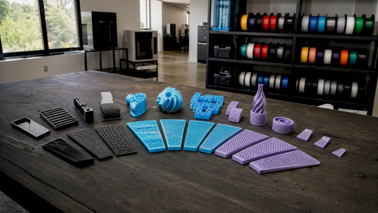
Different 3D printed surface textures on desktop

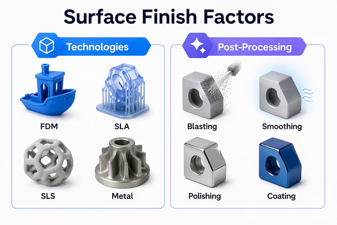
FDM (Fused Deposition Modeling) produces the most visible layer lines of any common process. Typical Ra values for FDM parts range from 10 to 30 μm, depending on layer height and material. PLA and ABS parts printed at 0.2 mm layer height show clear bead extrusion ridges that require sanding or chemical smoothing before use in consumer-facing applications.

SLA (Stereolithography) uses a UV laser to cure liquid resin, producing surfaces with Ra values as low as 1 to 3 μm right off the printer. The result is a near-glassy finish that requires minimal post-processing for aesthetic parts. However, support attachment points leave small scars that must be addressed before final use.

SLS (Selective Laser Sintering) fuses nylon powder, leaving a grainy, matte texture with Ra values typically between 6 and 12 μm. The surface has a sandpaper-like quality that works well for functional prototypes but needs bead blasting or dyeing for production parts.

Metal powder bed fusion processes, including DMLS and SLM, produce surfaces with Ra values ranging from 6 to 20 μm. Residual powder particles fused to the surface and layer lines both contribute to roughness. Post-machining or electropolishing is standard for sealing surfaces and bearing interfaces.

Technology Typical Ra Range Primary Surface Issue
FDM 10–30 μm Visible layer lines, bead ridges
SLA 1–3 μm Support scars, resin blush
SLS 6–12 μm Grainy powder texture
Metal DMLS/SLM 6–20 μm Fused powder, staircase effect
Material Jetting 1–4 μm Waxy surface, UV sensitivity

Infographic comparing 3D printing technologies and post-processing methods affecting surface finish

Print orientation compounds these effects. Surfaces printed at shallow angles relative to the build plate show the most pronounced staircase stepping. Vertical walls on FDM parts are smoother than 45-degree overhangs because the layer transitions are less visible. Surface finish in additive manufacturing is a critical functional parameter that affects fit, fluid dynamics, wear resistance, and fatigue life across all of these technologies.

What post-processing techniques enhance surface finish?

Post-processing is where manufacturers close the gap between as-printed texture and production-grade quality. The right method depends on material, geometry, required Ra value, and whether the part needs dimensional stability after finishing.

Media blasting and bead blasting are the most common first steps for SLS and metal parts. Blasting removes loose powder, smooths texture, and creates a uniform matte finish. It does not significantly alter dimensions, making it safe for tight-tolerance features. Media blasting and chemical smoothing effectively eliminate stair-stepping effects inherent to layered printing.

Chemical vapor smoothing works by exposing a part to solvent vapor that melts and redistributes the outermost surface layer. For FDM ABS parts, acetone vapor smoothing can reduce Ra from 20 μm down to 2 to 4 μm in minutes. The trade-off is slight dimensional change and the need for controlled ventilation. For nylon SLS parts, dedicated vapor smoothing systems like AMT PostPro3D achieve similar results with better repeatability.

Tumbling and vibratory finishing use abrasive media in a rotating drum to smooth small parts uniformly. This method works well for batches of small, geometrically simple parts but is size-limited and can round sharp edges that are functionally important.

Sanding and polishing remain the most controllable methods for achieving very low Ra values on accessible surfaces. Progressive grits from 120 to 2000, followed by polishing compound, can bring SLA or FDM parts to a mirror finish below 0.5 μm. The limitation is labor cost and the inability to reach internal channels or complex geometry.

Painting and dyeing add color and a protective layer simultaneously. Dyeing is particularly effective for SLS nylon, penetrating the surface rather than coating it, which preserves dimensional accuracy. Painting adds thickness, typically 50 to 100 μm per coat, which must be accounted for on mating surfaces.

Method Best For Ra Improvement Key Trade-off
Bead blasting SLS, metal Moderate Matte only, no gloss
Vapor smoothing FDM ABS, nylon High Slight dimensional change
Tumbling Small batch parts Moderate Size and geometry limited
Sanding/polishing Accessible surfaces Very high Labor intensive
Painting/dyeing Aesthetics, protection Low (coating) Adds thickness

Pro Tip: Specify your required Ra value before selecting a post-processing method. Working backward from the functional requirement, such as Ra 0.8 μm for a sealing surface, prevents over-processing and unnecessary cost. Learn more about the full spectrum of options in this 3D print finishes guide.

How does surface finish affect functional performance?

Surface roughness is an engineering variable with direct consequences for part performance. Mismanaging surface finish causes technical failures including leaking gaskets, seized parts, and premature fatigue because surface anomalies initiate stress cracks. This is not a cosmetic concern. It is a structural one.

The fatigue life relationship is quantitative. Reducing surface roughness from Ra 3.2 μm to 0.8 μm in metal parts produces fatigue strength improvements of 15 to 30%. For a load-bearing bracket or a cyclic-stress component in a medical device, that improvement can be the difference between a 10-year service life and a premature failure.

Friction and wear behavior depend on surface texture in ways that are not always intuitive. Rough surfaces create higher initial friction and accelerate wear in sliding contact. However, some applications require specific surface textures to retain lubricants, and over-finishing can starve mechanical assemblies of necessary lubrication. A bearing journal polished to Ra 0.1 μm may actually perform worse than one finished to Ra 0.4 μm because the lubricant film cannot be maintained.

Sealing performance adds another layer of complexity. Both too rough and too smooth surfaces can cause leaks or micro-leaks in gasket interfaces. A controlled Ra value, typically between 1.6 and 3.2 μm for most elastomeric gaskets, creates enough texture for the gasket to conform without allowing leak paths through deep valleys.

Fluid dynamics in internal channels are also affected. Rough internal surfaces in printed manifolds or heat exchangers increase turbulent flow and pressure drop. For high-flow hydraulic components, this translates directly to energy loss and heat generation. Electropolishing or abrasive flow machining of internal channels is standard practice in precision fluid systems.

Dimensional accuracy at assembly depends on finish as well. A shaft printed to nominal diameter with Ra 15 μm will measure differently than one finished to Ra 1.6 μm because the roughness peaks add effective material. Understanding this relationship is covered in detail in precision 3D part qualities that every engineer should account for at the design stage.

What design decisions optimize surface finish from the start?

The most cost-effective surface finish strategy begins in CAD, not at the finishing bench. Surface finish is a decisive factor in lifecycle costs and reliability, and decisions made during design and print setup determine how much post-processing will be required.

  1. Orient critical surfaces away from support contact. Support structure removal causes surface scarring that compromises dimensional accuracy if not accounted for at the design stage. Placing cosmetic or functional surfaces on self-supporting faces eliminates this problem entirely.

  2. Rotate parts to minimize staircase effects on key features. Rotating parts by 45 or 90 degrees optimizes surface finish on sloped features and reduces post-processing time and cost. A cylindrical bore printed vertically will have a smoother inner wall than one printed horizontally.

  3. Reduce layer height on finish-critical parts. Dropping from 0.2 mm to 0.1 mm layer height on an FDM part roughly halves the visible staircase amplitude. Print time increases, but post-processing time decreases, and the net cost is often lower for small-batch production.

  4. Specify Ra requirements on your drawing before quoting. Suppliers cannot hit a target they have not been given. Defining Ra values for sealing surfaces, bearing interfaces, and cosmetic faces at the RFQ stage prevents mismatched expectations and rework.

  5. Account for finishing stock in your CAD model. If a surface will be sanded or machined after printing, add 0.3 to 0.5 mm of material to that face. This preserves final dimensions after material removal.

Pro Tip: For manufacturing-grade 3D printed parts, treat surface finish as a design input, not an afterthought. Document finish requirements in your technical drawing the same way you would a tolerance or material callout.

Support structure scarring is a major contributor to surface defects, and anticipating this during CAD design reduces costly rework and maintains accuracy. The best manufacturers build finish considerations into their design review checklist, not their inspection report.

Key takeaways

Surface finish in 3D printing is a functional engineering parameter that must be specified, designed for, and controlled from the first CAD decision to the final post-processing step.

Point Details
Technology sets the baseline FDM, SLA, SLS, and metal processes each produce distinct Ra ranges that define your starting point.
Post-processing closes the gap Methods like vapor smoothing, bead blasting, and polishing can reduce Ra by an order of magnitude.
Finish drives functional outcomes A 15 to 30% fatigue strength gain is achievable by reducing Ra from 3.2 μm to 0.8 μm in metal parts.
Over-finishing carries real risk Surfaces polished below optimal Ra can fail to retain lubricant, causing premature wear in assemblies.
Design orientation is the cheapest fix Rotating a part 45 to 90 degrees during setup reduces staircase effects without adding cost.

Surface finish is the variable most manufacturers underestimate

I have reviewed hundreds of part drawings from product developers who specify tight dimensional tolerances down to 0.05 mm but leave the surface finish field blank. That blank field is where failures are born. A gasket surface with Ra 12 μm will leak under pressure cycling regardless of how accurate the bore diameter is. A sliding shaft with Ra 25 μm will wear its mating bore in weeks, not years.

The misconception I encounter most often is that surface finish is a cosmetic concern addressed at the end of the process. The reality is the opposite. Finish requirements should appear on the drawing before the first print parameter is set. The technology choice, orientation, layer height, and post-processing sequence all flow from that specification.

What I find genuinely encouraging is how much the as-printed baseline has improved. 3DEO’s Intelligent Layering technology produces production-grade metal parts with smooth surfaces and tight tolerances directly off the printer, which challenges the assumption that additive manufacturing always requires heavy post-processing. That capability is spreading across the industry. The gap between additive and machined surface quality is narrowing every year.

My practical advice: treat surface finish as a first-class design parameter. Write it on the drawing. Discuss it with your print supplier at the quoting stage. And if you are unsure what Ra value your application requires, look at the equivalent machined part specification and use that as your target. The post-processing methods available today can hit almost any target. The question is whether you have defined the target clearly enough to hit it.

— Justin

How Cc3dlabs helps manufacturers achieve production-grade surface finish

https://cc3dlabs.com

Cc3dlabs, based near Philadelphia, works with manufacturers and product developers who need more than a rough prototype. Their FDM printing capabilities cover a range of engineering-grade materials, and their post-processing options include sanding, painting, and finishing tailored to functional requirements. Every project starts with a design review that includes surface finish specification, so parts arrive ready for assembly, not for rework. For teams managing batch production or iterating on functional components, Cc3dlabs offers fast turnaround, free online estimates, and direct design support. Explore their full range of capabilities on the 3D printing services page and request a quote for your next production run.

FAQ

What is surface finish in 3D printing?

Surface finish in 3D printing refers to the texture and roughness of a part’s outer surface, measured as roughness average (Ra) in micrometers. It affects how a part looks, how it fits with mating components, and how it performs under mechanical stress or fluid pressure.

Which 3D printing process produces the smoothest surface?

SLA and material jetting produce the smoothest as-printed surfaces, with Ra values as low as 1 to 3 μm. FDM produces the roughest baseline finish, typically between 10 and 30 μm, and almost always requires post-processing for functional or cosmetic applications.

How does surface roughness affect fatigue life?

Reducing Ra from 3.2 μm to 0.8 μm in metal parts improves fatigue strength by 15 to 30%. Surface irregularities act as stress concentration points where fatigue cracks initiate, so smoother surfaces directly extend component service life.

Can over-polishing a 3D printed part cause problems?

Yes. Some mechanical assemblies require a specific surface texture to retain lubricant. Polishing a surface below the optimal Ra value can prevent lubricant film formation, leading to metal-to-metal contact and accelerated wear.

When should surface finish be specified in the design process?

Surface finish requirements should be specified on the technical drawing before the first print parameter is selected. Early specification allows the print supplier to choose the correct technology, orientation, and post-processing sequence to hit the target at the lowest cost.

Engineer working on CAD modeling at drafting table

CAD Modeling Workflow 2026: Engineer’s Optimization Guide


TL;DR:

  • A modern CAD workflow in 2026 relies on disciplined parametric modeling, PLM-enforced version control, and 3MF exports to produce print-ready parts efficiently. Consistently sequencing assembly, validation, and detail features prevents costly rework and ensures reliable manufacturing outcomes. Process discipline, rather than software upgrades, remains the key to optimizing design and production efficiency.

A modern CAD modeling workflow is a structured sequence of design operations that, when executed correctly, reduces iteration time and produces print-ready geometry with fewer errors. For product developers and engineers targeting 3D printing efficiency in 2026, the difference between a functional workflow and a chaotic one comes down to three disciplines: parametric modeling in tools like SOLIDWORKS or CATIA, data management through PDM/PLM systems, and export practices built around the 3MF file format. Get those three right, and every downstream step from CAE validation to physical print becomes faster and more predictable.

What are the essential tools for a CAD modeling workflow in 2026?

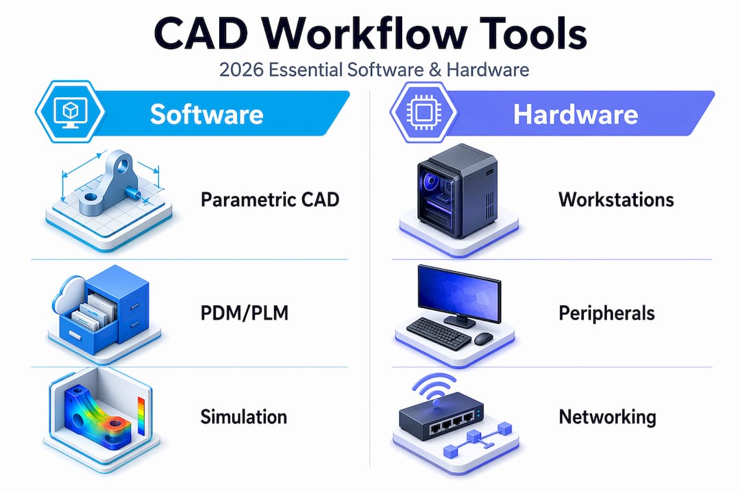
The foundation of any efficient CAD design process in 2026 is software that supports parametric, feature-based modeling. SOLIDWORKS, CATIA, and Solid Edge are the three platforms most widely used in professional product development because each supports full constraint-driven geometry, assembly management, and direct integration with simulation and manufacturing tools. Choosing between them depends on industry context: CATIA dominates aerospace and automotive, SOLIDWORKS leads in mechanical product design, and Solid Edge offers strong sheet metal and frame capabilities.

Hands using graphic tablet for CAD design

Hardware matters more than most engineers admit. Complex assemblies with hundreds of components demand workstations with high single-core clock speeds, at least 64 GB of RAM, and certified graphics cards from NVIDIA Quadro or AMD Radeon Pro lines. Running a 400-part assembly on an underpowered machine does not just slow you down. It introduces instability that corrupts rebuild sequences and forces manual intervention.

PDM/PLM systems replace shared folders as the backbone of file management. They enforce check-in/check-out protocols, maintain full version history, and apply naming conventions automatically. Without them, teams routinely work on outdated geometry and produce conflicting revisions that cost days to reconcile.

Tool category Recommended options Primary benefit
Parametric CAD SOLIDWORKS, CATIA, Solid Edge Constraint-driven design and assembly management
PDM/PLM SOLIDWORKS PDM, Windchill, Teamcenter Version control and change management
Simulation (CAE) ANSYS, Abaqus, SOLIDWORKS Simulation Structural, thermal, and fluid validation
Slicing/export PrusaSlicer, Bambu Studio, Chitubox 3MF and G-code generation for printing

Infographic comparing CAD software and hardware tools

Pro Tip: Keyboard shortcuts and templates can improve productivity by 20 to 30% in professional CAD environments. Build a custom startup template with your standard units, material libraries, and drawing formats before starting any new project.

How to structure your CAD workflow steps for 3D printing projects

A well-structured CAD workflow follows a deliberate sequence. Skipping steps or reordering operations to save time upfront almost always creates larger problems during validation and export. The following sequence applies to parametric solid modeling for additive manufacturing projects.

  1. Define the assembly structure first. Before modeling a single part, map out the functional subassemblies. Identify which components move, which are fixed, and where the critical interfaces are. This prevents structural rework later when parts fail to mate correctly.

  2. Create master sketches to drive parametric design. A master sketch is a 2D layout sketch at the assembly level that defines key dimensions, reference planes, and spatial relationships. Changes to the master sketch propagate through all dependent parts automatically, which is the core advantage of parametric modeling.

  3. Model base volumes before adding detail features. Build the primary solid geometry first: extrusions, revolves, and lofts that define the overall shape. Leave fillets, chamfers, threads, and surface textures for later. Applying fillets too early creates large rebuild penalties and should be postponed until base volumes are fully validated.

  4. Validate geometry before detailing. Run interference checks and confirm wall thicknesses meet your printer’s minimum requirements before adding any cosmetic or functional detail features. Catching a wall thickness violation at this stage takes minutes. Catching it after threading and filleting takes hours.

  5. Add detail features in a controlled sequence. Apply threads, fillets, chamfers, and surface finishes only after base geometry passes validation. Group similar operations together to minimize rebuild cycles.

  6. Embed review steps throughout, not just at the end. Formal review steps embedded throughout the process reduce rework iterations and drawing errors significantly. Schedule a peer review after step 3 and again after step 5.

Pro Tip: For complex assemblies, use a top-down modeling approach where the master sketch lives at the assembly level. For simpler parts, bottom-up modeling is faster and easier to manage.

Workflow approach Best for Key trade-off
Top-down (master sketch driven) Complex multi-part assemblies Higher setup time, lower rework risk
Bottom-up (independent parts) Simple parts and small assemblies Faster start, harder to propagate global changes
Hybrid Mid-complexity products with modular subassemblies Balances speed and control

How does CAD integrate with CAM, CAE, and PLM for manufacturing?

CAD is the source of truth for geometry and tolerances. Every downstream system, whether it is a simulation solver or a CNC toolpath generator, reads from the CAD model. That dependency makes the quality of the CAD model the single largest variable in manufacturing outcome. CAD-CAM-CAE integration through PLM coordination ensures that only validated designs proceed to production.

The integration loop works as follows:

  • CAD defines geometry, tolerances, and material specifications.
  • CAE (tools like ANSYS or SOLIDWORKS Simulation) validates structural, thermal, and fluid performance against design requirements.
  • CAM (tools like Mastercam or Fusion 360 CAM) generates toolpaths and manufacturing instructions from validated CAD geometry.
  • PLM (Windchill, Teamcenter, or SOLIDWORKS PDM) coordinates the gating between each phase, controls who can approve transitions, and triggers re-validation when edits occur after approval.

The gating function of PLM is what most teams underuse. Without formal gates, engineers edit geometry post-CAE without triggering a new simulation run. That gap between the validated model and the manufactured model is where costly field failures originate. Every geometry change after CAE sign-off must restart the validation cycle. PLM enforces that rule automatically when configured correctly.

Phase Primary tool Output
Geometry definition SOLIDWORKS, CATIA Parametric solid model with tolerances
Performance validation ANSYS, Abaqus Simulation report and pass/fail status
Manufacturing prep Mastercam, Fusion 360 CAM Toolpaths, G-code, or print instructions
Change control Windchill, Teamcenter Approved revision with audit trail

What file formats optimize CAD models for 3D printing?

3MF is the preferred format for additive manufacturing in 2026. Unlike STL, which stores only surface triangles with no color, material, or metadata, 3MF packages geometry, slicer settings, color assignments, material specifications, and project information inside a single ZIP/XML container. That means a 3MF file sent to a printer or service bureau carries everything needed to reproduce the design intent without a separate specification document.

STL remains common because legacy workflows depend on it, but its limitations create real problems. STL files carry no unit information, no material data, and no tolerance context. A print service receiving only an STL file must make assumptions about scale, orientation, and material that the designer never intended. Those assumptions cause the “mysterious” print failures that engineers spend hours diagnosing.

The right export package for any serious 3D printing project includes three files. First, the 3MF for the printer or service bureau. Second, a STEP file for cross-software review and manufacturing quotes, since STEP preserves solid geometry and works across all major CAD platforms. Third, a 2D drawing with GD&T callouts that documents tolerances, critical surfaces, and inspection requirements.

Pro Tip: Before exporting, run a mesh quality check inside your CAD tool or a dedicated utility like Netfabb or Meshmixer. Look for non-manifold edges, inverted normals, and gaps in the mesh. These defects are invisible in the CAD environment but cause slicer failures that are hard to trace back to their source. Learn more about optimizing CAD file formats for additive manufacturing.

What common mistakes slow down CAD modeling efficiency?

The most expensive mistake in parametric CAD is applying heavy operations too early. Moving fillets and threads to the end of the feature tree is not just a style preference. Reversing detail and main shape operations causes considerable time loss. For complex models with 400 or more cavities, restructuring the feature order has reduced computation time from over an hour to seconds.

Version control failures are the second most common source of rework. Engineers working from shared folders without PDM often edit the wrong revision, overwrite a colleague’s changes, or submit geometry that was superseded two days earlier. Strong data management practices like templates, naming conventions, and version control underpin sustainable workflow efficiency. There is no software feature that compensates for absent version discipline.

GD&T errors are subtler but equally damaging. Tolerance attachments and derived datum controls are often not automatically validated by CAD constraint solvers, which means incorrect or missing GD&T semantic attachments require engineering review even in automated workflows. Choosing between ISO 1101 and ASME Y14.5 is not a minor formatting decision. It directly affects inspection outcomes and manufacturing conformance, particularly for aerospace and medical applications.

  • Apply fillets, chamfers, and threads only after base geometry validation passes.
  • Use PDM check-in/check-out for every file, even on solo projects.
  • Verify GD&T callouts against the applicable standard (ISO 1101 or ASME Y14.5) before releasing drawings.
  • Run interference analysis at the assembly level before detailing individual parts.
  • Automate repetitive exports with macros to eliminate manual errors and save time.

“Most CAD workflow efficiency gains come from disciplined process improvements rather than solely new software features.” — Efficient modeling workflow guide

Key takeaways

An optimized CAD modeling workflow in 2026 requires parametric discipline, PLM-enforced version control, and 3MF-based exports to produce reliable, print-ready geometry at speed.

Point Details
Structure before modeling Define assembly hierarchy and master sketches before creating any part geometry.
Delay detail features Apply fillets, threads, and chamfers only after base volumes pass interference checks.
Use PDM/PLM for all files Version control through Windchill or SOLIDWORKS PDM prevents costly revision conflicts.
Export 3MF plus STEP Send 3MF for printing and STEP with 2D drawings for manufacturing quotes and review.
Gate every phase PLM must trigger re-validation after any geometry edit post-CAE approval.

Why process discipline beats software upgrades every time

I have watched teams spend significant budget on new CAD seats and simulation licenses, then wonder why their iteration cycles did not shorten. The answer is almost always the same. The software was not the bottleneck. The process was.

The most impactful change I have seen in any CAD environment was not a software upgrade. It was a team that committed to top-down assembly structuring and master sketch discipline. Their rebuild times dropped from hours to minutes on assemblies that had previously been nightmares to modify. The tools were the same. The sequence changed.

What I tell every product developer I work with is this: map your current workflow on paper before touching any settings. Identify where you are applying operations out of order, where files live outside PDM, and where GD&T callouts are being added as afterthoughts. Those three areas account for the majority of rework in most teams I have seen.

The future CAD workflows that will define 2026 and beyond are not defined by AI-assisted sketching or cloud rendering. They are defined by teams that treat their modeling sequence as a living process, review it regularly, and enforce it consistently. Technology amplifies discipline. It does not replace it.

— Justin

How Cc3dlabs supports your CAD-to-print workflow

When your CAD model is ready for production, the transition from file to physical part should be frictionless. Cc3dlabs specializes in handling complex CAD files optimized for additive manufacturing, accepting 3MF, STEP, and native formats to preserve your design intent from model to print.

https://cc3dlabs.com

Whether you need a single functional prototype or a batch of production parts, Cc3dlabs’ professional 3D printing services near Philadelphia cover multi-color printing, metrology-grade scanning, and design support for engineers who need accurate, durable results fast. If you want to see how 3D printing drives product innovation in 2026, the Cc3dlabs team is ready to take your optimized CAD files and turn them into parts that perform.

FAQ

What is a CAD modeling workflow?

A CAD modeling workflow is a structured sequence of design steps that takes a product from concept geometry to a validated, export-ready model. It includes assembly structuring, parametric modeling, simulation validation, and file export for manufacturing or 3D printing.

What is the best CAD software for 3D printing in 2026?

SOLIDWORKS and Fusion 360 are the most widely used platforms for 3D printing-focused design because both support parametric modeling and direct 3MF export. CATIA and Solid Edge are preferred in aerospace and automotive contexts where tighter PLM integration is required.

Why is 3MF better than STL for 3D printing?

3MF stores geometry alongside colors, materials, slicer settings, and project metadata inside a single ZIP/XML package, while STL stores only surface triangles with no unit or material information. That metadata gap in STL files causes scale errors and print failures that 3MF eliminates by design.

How does PLM improve CAD workflow efficiency?

PLM systems like Windchill and Teamcenter gate each design phase, enforce re-validation after geometry edits, and maintain a full audit trail of approved revisions. Without PLM, teams routinely manufacture from outdated or unapproved geometry, which is the leading cause of costly production rework.

When should you apply fillets and chamfers in a CAD model?

Apply fillets, chamfers, and threads only after base geometry has passed interference checks and wall thickness validation. Adding detail features too early creates rebuild penalties that can extend computation time from seconds to over an hour on complex assemblies.