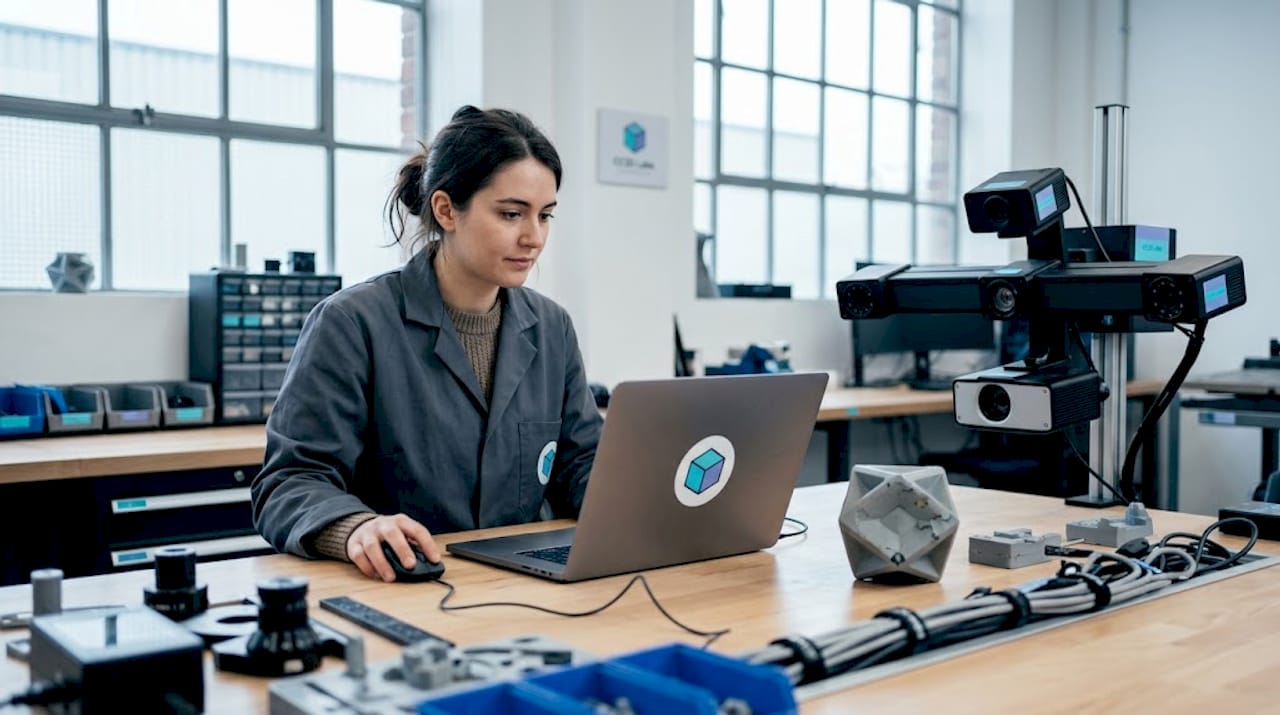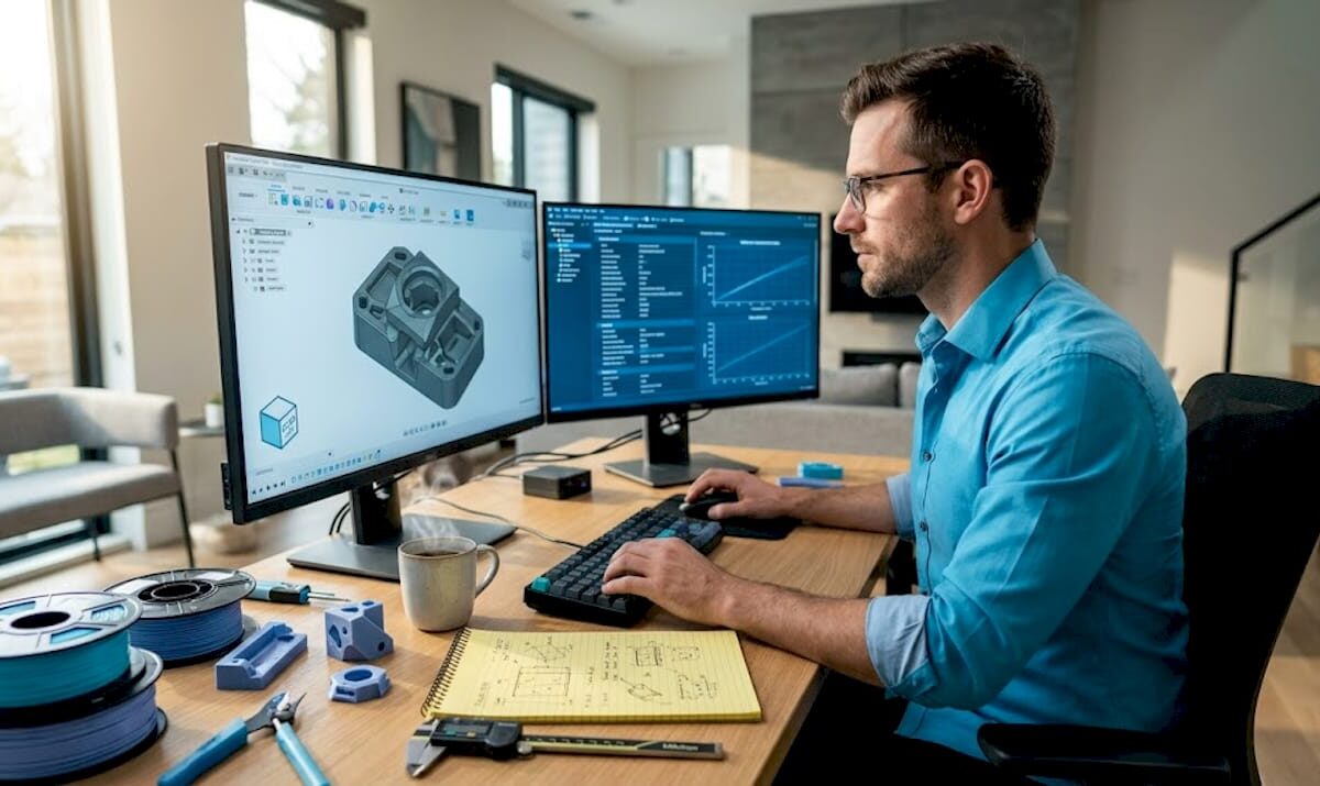
Engineer scanning metal part at workbench

Unlock 3D scanning: boost design accuracy and prototyping


TL;DR:

  • 3D scanning provides precise digital models, faster prototyping, and reliable quality control.
  • Choosing the right technology depends on accuracy, object size, surface, and budget.
  • Integrating 3D scanning early improves design accuracy, reduces errors, and accelerates workflows.

3D scanning gets dismissed as a glorified copy machine for 3D printing. That misunderstanding costs product teams weeks of rework and thousands in avoidable errors. In reality, 3D scanning is one of the most powerful tools available for businesses that need precise digital models, faster prototyping cycles, and reliable quality control. This guide walks you through how 3D scanning works, the main technologies available, the real business benefits, and how to integrate scan data into your design and manufacturing workflows without the common pitfalls.

Table of Contents

Key Takeaways

Point Details
3D scanning basics 3D scanning transforms real objects into accurate digital models for design and prototyping.
Top technologies Laser triangulation, structured light, and photogrammetry each suit different accuracy and use-case needs.
Business benefits 3D scanning saves time, reduces errors, and enables rapid iteration in product development and manufacturing.
Workflow integration Scanned data seamlessly fits into CAD and production pipelines, connecting design with manufacturing.
Real-world success tips Preparation, surface treatment, and calibration improve scan quality and project success.

How 3D scanning works: The basics explained

At its core, 3D scanning captures the exact geometry and surface details of a physical object and converts that data into a digital model. That model can then be edited, analyzed, reproduced, or fed directly into a CAD (computer-aided design) system. The process has three main stages: data capture, point cloud creation, and mesh or model generation.

During data capture, the scanner emits light, laser beams, or uses cameras to measure the surface of an object from multiple angles. Each measurement records the position of a point in 3D space. Thousands or even millions of these points combine to form a point cloud, which is essentially a dense map of the object’s surface geometry. That point cloud is then processed into a mesh, a connected surface made of triangles, which becomes the usable 3D model.

The three most common scanning technologies are:

  • Laser triangulation: Projects a laser line or point onto the surface; a sensor reads the reflected angle to calculate position. Laser triangulation is highly accurate for short-range work and fine detail.
  • Structured light: Projects a pattern of light (often stripes) onto the object and uses cameras to measure how the pattern deforms across the surface. Fast and excellent for medium-sized parts.
  • Photogrammetry: Uses overlapping photographs taken from different angles to reconstruct a 3D model mathematically. Cost-effective and scalable for larger objects.

Learning how 3D scanning optimizes workflows early in a project helps teams avoid costly design revisions later.

Pro Tip: Lighting and object positioning matter more than most people expect. Consistent, diffused lighting reduces shadows and surface noise, which directly improves point cloud density and model accuracy.

A poorly set up scan environment can introduce errors that ripple through every downstream step, from CAD modeling to final part inspection. Investing 15 minutes in proper setup saves hours of cleanup.

Main types of 3D scanning technologies compared

Now that you know the basics, let’s compare the main 3D scanning techniques so you can match the right tool to your project.

Choosing the wrong scanning method is one of the most common mistakes product teams make. Each technology has a distinct performance profile depending on accuracy needs, object size, surface type, and budget.

Technology Accuracy Speed Cost Best for
Laser triangulation Very high Moderate Medium-high Small parts, fine detail
Structured light High Fast Medium Mid-size parts, smooth surfaces
Photogrammetry Moderate Slow Low Large objects, outdoor use
CT scanning Extremely high Slow Very high Internal geometry, medical

Here is a simple process for matching your scanning method to your application:

  1. Define your accuracy requirement. Engineering tolerances under 0.05mm demand laser triangulation or CT scanning.
  2. Assess your object size. Larger objects favor photogrammetry or structured light; small precision parts favor laser-based methods.
  3. Evaluate the surface. Reflective or dark surfaces need special preparation regardless of technology.
  4. Set your budget. Photogrammetry is the most accessible entry point; CT scanning is reserved for high-value inspection needs.
  5. Consider turnaround time. Structured light scanning is typically the fastest for medium-complexity parts.

Understanding the key 3D scanning techniques available helps you ask better questions when working with a scanning service provider.

Pro Tip: For highly detailed engineering parts or small components, laser triangulation consistently delivers the best results. It is the standard choice for metrology-grade work where tolerances are tight and repeatability is critical.

Key benefits for product development and manufacturing

With the options in mind, let’s look at the real business benefits of integrating 3D scanning into your development process.

The most immediate gain is the elimination of manual measurement. Traditional calipers and coordinate measuring machines (CMMs) are slow, operator-dependent, and limited in the complexity of geometry they can capture. 3D scanning captures the full surface of a part in minutes, with far less human error involved.

Designer measuring prototype with digital calipers

Workflow factor Traditional method 3D scanning method
Measurement time (medium part) 2 to 4 hours 15 to 45 minutes
Error rate Higher (operator-dependent) Significantly lower
Geometry complexity handled Limited Full freeform surfaces
Iteration speed Slow Fast
Documentation quality Manual records Full digital archive

The real-world impact spans multiple business functions:

  • Part design: Capture existing components with no original CAD file and rebuild them accurately.
  • Reverse engineering: 3D scanning significantly increases accuracy in reverse engineering and prototyping, reducing guesswork entirely.
  • Quality control: Compare scanned production parts against the original CAD model to catch deviations before they become costly defects.
  • Tooling verification: Confirm that molds and fixtures match design intent before committing to full production runs.

Teams focused on ensuring 3D scan quality for manufacturing report faster iteration cycles and fewer engineering change orders. For businesses doing reverse engineering with 3D scanning, the ability to digitize legacy parts without original drawings is a significant competitive advantage.

The compounding effect is real. Fewer errors early in development mean fewer corrections late, which directly reduces cost per prototype and shortens time to market.

From scan to workflow: Where and how 3D data is used

Understanding the benefits, let’s explore where 3D scan data delivers real impact in business workflows.

A raw point cloud is useful, but its true value comes when it is converted into a workable CAD model. Most professional scanning workflows use software like Geomagic, Artec Studio, or SOLIDWORKS to process the point cloud into a clean mesh, then into a parametric CAD file that designers can modify and manufacture from.

Here are the most common ways businesses use 3D scan data:

  • Reverse engineering: Recreate parts with no existing drawings, especially for legacy components or competitor benchmarking.
  • Quality inspection: Overlay the scan against the original CAD model to produce a color deviation map showing where parts are out of tolerance.
  • Tooling and fixture verification: Confirm that production tooling matches design specifications before first-article inspection.
  • Archiving: Build a permanent digital record of physical assets, molds, or prototypes for future reference.
  • Design iteration: Scan a physical prototype, bring it into CAD, refine it, and print or machine the next version faster.

“Modern 3D scanning streamlines the full development pipeline for new and legacy products, reducing the gap between physical reality and digital design intent.”

Exploring 3D scanning in CAD workflows shows just how tightly scanning integrates with modern design tools. Teams that understand using 3D scan data in CAD can move from physical object to production-ready file in a fraction of the time traditional methods require.

The key insight is timing. Scanning should not be an afterthought reserved for inspection. Integrating it early, at the concept and first-prototype stage, is where the biggest gains in speed and accuracy happen.

Common challenges and tips for getting reliable 3D scans

To wrap up the core guide, let’s address the most common snags and how smart teams get reliable results consistently.

Even with good equipment, scan quality can suffer if preparation and technique are not right. Surface type and environment directly influence scan accuracy, and skipping preparation steps is the fastest way to produce unusable data.

The most common challenges and how to address them:

  • Reflective surfaces: Shiny metals and plastics scatter laser or structured light unpredictably. Apply a temporary matte scanning spray to create a uniform, readable surface.
  • Dark or black surfaces: These absorb light rather than reflecting it, creating data gaps. Scanning spray also solves this problem in most cases.
  • Object movement: Even small vibrations during a scan introduce misalignment. Use a stable fixture or turntable to hold the part securely.
  • File misalignment: When combining multiple scan passes, poor alignment creates visible seams in the mesh. Use reference markers (small adhesive targets) placed on the object before scanning to give the software fixed registration points.
  • Calibration drift: Scanners can drift out of calibration over time or with temperature changes. Always run a calibration check before a critical scan session.

Pro Tip: For complex objects that require multiple scan passes, place reference markers on the object before you start. These give the alignment software fixed anchor points, which dramatically reduces mesh errors and cleanup time afterward.

Visit our tips for high quality 3D scanning resource for a deeper breakdown of preparation and post-processing best practices. Proper technique at the scan stage protects every hour of CAD work that follows.

Our take: Why mastering 3D scanning drives real innovation

Most conversations about 3D scanning focus on speed and cost savings. Those are real, but they are not the most important part of the story.

What we see consistently at CC 3D Labs is that businesses which integrate scanning early in their process do not just move faster. They think differently. When your team can digitize any physical object in minutes and bring it into a shared CAD environment, the collaboration between designers, engineers, and production teams changes fundamentally. Decisions get made with real geometry, not assumptions.

The conventional wisdom treats scanning as a QC or reverse engineering tool used after design is mostly done. That is backwards. The teams that leapfrog competitors use real-world 3D scanning insights to inform design from the very first prototype. They catch fit and function issues in the digital model before a single part is machined or molded.

The future of product development is agile, and agility requires closing the loop between physical and digital as fast as possible. 3D scanning is the bridge. Mastering it is not a technical upgrade. It is a strategic one.

Level up your workflow with CC3DLabs 3D scanning and printing solutions

Ready to put these insights into action for your business?

https://cc3dlabs.com

CC 3D Labs offers metrology-grade 3D scanning services paired with end-to-end CAD modeling and pro-level 3D printing for product developers and manufacturers near Philadelphia and beyond. Whether you need to digitize a legacy part, verify a production run, or accelerate your prototyping cycle, our team handles the full workflow from scan to finished part. Browse our CAD project gallery to see real examples of scan-to-print projects, or request a free estimate to get started on your next build.

Frequently asked questions

What is 3D scanning used for in business?

Businesses use 3D scanning for design accuracy, prototyping, reverse engineering, and quality control. It significantly increases accuracy in reverse engineering and prototyping compared to manual measurement methods.

Which 3D scanning method is best for fine detail?

Laser triangulation is best for short-range, high-precision applications and is the standard choice for capturing highly detailed or small parts at engineering tolerances.

What impacts 3D scanning accuracy?

Surface reflectivity, ambient lighting, and scanner calibration are the three biggest factors. Surface type and environment require careful preparation to achieve reliable, repeatable scan results.

Can 3D scan data be edited or modified?

Yes. Scan data is processed into a mesh and then converted to a parametric CAD model, which designers can fully edit, refine, and adapt for manufacturing or further prototyping.

Woman inspecting prototype 3D print at workbench

How to design 3D prints: reliable prototypes & parts


TL;DR:

  • Proper 3D print design requires understanding material, process, and geometry constraints.
  • Orientation and support planning are crucial for part strength, finish, and print success.
  • Final validation with testing and adjustments ensures reliable, functional 3D printed parts.

Poor 3D print design costs more than just filament. Parts that don’t fit, walls that crack under load, or holes too tight for their fasteners can stall an entire product development cycle. The root cause is almost always the same: the design didn’t account for how 3D printing actually works. This guide walks you through every stage, from defining requirements and choosing materials to setting tolerances, orienting parts for strength, and validating your file before the first layer goes down. Follow these principles and you’ll spend less time reprinting and more time building.

Table of Contents

Key Takeaways

Point Details
Start with clear requirements Clarify part function, material, and print method before designing to minimize errors.
Follow proven geometry rules Respect wall thickness, tolerances, and overhang limits for a reliable print.
Orient for strength and ease Align parts for maximum real-world durability and minimize support and warpage risks.
Validate before printing Double-check for potential design errors and simulate part fits or stress if possible.

Gathering requirements and planning your 3D print

Every reliable 3D printed part starts with a clear answer to one question: what does this part actually need to do? That sounds obvious, but it’s where most design problems begin. A concept model shown to stakeholders has completely different requirements than a bracket bolted into a working assembly. Treating them the same way is a fast path to wasted prints.

Start by categorizing your part’s purpose:

  • Concept model: Visual representation only. Dimensional accuracy matters less than speed and cost.
  • Fit and form prototype: Must match final geometry closely so you can test assembly clearances and ergonomics.
  • Functional prototype: Needs to perform under real loads, temperatures, or environmental exposure.
  • End-use part: Must meet full mechanical, chemical, and aesthetic specifications.

Once you know the stage, material selection follows logically. Choosing materials by prototype stage is straightforward: PLA and FDM work well for early concepts, while PETG and Nylon SLS are better suited to functional parts that need toughness and temperature resistance. For materials for durable parts, the tradeoff between cost, printability, and mechanical performance is worth understanding before you commit to a process.

Stage Recommended material Recommended process
Concept PLA FDM
Fit/form PETG, Resin FDM, SLA
Functional Nylon, PETG SLS, FDM
End-use Nylon, Metal SLS, DMLS

The process you choose also determines what design constraints you’ll work within. FDM is affordable and fast but produces visible layer lines and lower Z-axis strength. SLA gives you fine detail and smooth surfaces but can be brittle. SLS produces strong, isotropic parts without support structures. Metal processes offer the best mechanical properties but require tighter design control. Selecting 3D printing methods early in the workflow prevents costly redesigns later.

Also plan ahead for post-processing. If a part will be sanded, painted, or machined after printing, you need extra material stock in those areas. If it will be assembled with hardware inserts, account for heat-set or press-fit tolerances in the original CAD model.

Pro Tip: Write a one-paragraph “part brief” before opening your CAD software. List the function, material preference, process, expected loads, and any assembly interfaces. This single document prevents the most common design drift that leads to reprints.

Design principles: Dimensions, tolerances, and geometry

With your requirements defined, the next step is translating them into geometry that a printer can actually produce reliably. This is where most engineers either over-trust their CAD model or under-estimate how much the printing process changes the final dimensions.

Wall thickness is the first constraint to set. Minimum wall thickness varies by technology: FDM needs at least 1.2mm for structural walls, SLA can go as thin as 0.5mm, SLS works well at 0.8mm and above, and metal processes typically require 0.5 to 1mm depending on geometry. Going thinner than these limits risks incomplete walls, warping, or print failures.

Infographic: 3D printing design basics summary

Tolerances define how closely the printed part matches your CAD dimensions. The numbers matter: FDM holds ±0.2 to 0.5mm, SLA achieves ±0.05 to 0.15mm, SLS and MJF land at ±0.15 to 0.3mm, and metal processes reach ±0.05 to 0.2mm. Design your clearances and fits around these real-world numbers, not theoretical CAD perfection.

Process Typical tolerance Min wall thickness
FDM ±0.2 to 0.5mm 1.2mm
SLA ±0.05 to 0.15mm 0.5mm
SLS/MJF ±0.15 to 0.3mm 0.8mm
Metal (DMLS) ±0.05 to 0.2mm 0.5 to 1mm

Geometry choices have a major impact on print reliability. Follow these rules:

  1. Keep overhangs at or below 45 degrees from vertical to avoid needing supports.
  2. Limit unsupported bridges to 5mm or less for FDM; SLA and SLS handle longer spans better.
  3. Add chamfers or fillets to sharp interior corners to reduce stress concentration.
  4. Orient tall, thin features so they print along the XY plane rather than growing vertically.
  5. For outdoor parts, account for UV and thermal cycling in both material choice and wall thickness.

Holes are a consistent pain point. They almost always print undersized due to material flow and thermal contraction. If your design calls for a 6mm bolt hole, model it at 6.2 to 6.4mm and test before committing to a full batch. Understanding key 3D printing terms like “elephant’s foot” and “shrinkage” helps you anticipate these effects before they show up in your parts.

Anisotropy, meaning the difference in strength depending on direction, is critical for functional parts. The XZ and XY planes are significantly stronger than the Z axis in layer-based processes. Design load-bearing features so stress runs parallel to the print bed, not perpendicular to it.

Pro Tip: Use a tolerance guidelines reference alongside your CAD software. Avoid common geometry mistakes like modeling perfectly vertical walls without draft or adding decorative thin ribs that the printer simply cannot reproduce.

Maximizing strength and function through orientation and supports

Once your dimensions and geometry are locked in, how you orient the part in the build volume becomes one of the most powerful variables you control. Two identical CAD files can produce parts with dramatically different real-world performance based on orientation alone.

Man adjusting 3D print orientation at desk

The core rule is straightforward: orient loads parallel to the XY plane because the Z axis is weaker due to layer bonding. A bracket printed flat on the bed will resist bending forces far better than the same bracket printed standing upright. This isn’t just a guideline, it’s the physical reality of how layers fuse.

Here’s what to consider when choosing orientation:

  • Place the largest flat surface on the build plate to maximize adhesion and minimize warpage.
  • Orient critical surfaces face-down for SLA to get the best surface finish where it matters.
  • For SLS and MJF, orientation affects surface texture but not strength as dramatically, since these processes are more isotropic.
  • Avoid orienting thin walls vertically in FDM; they’re prone to vibration and layer separation.
  • Minimize the number of support structures needed, especially in hard-to-reach internal cavities.

Supports are necessary in many designs, but they add print time, cost, and post-processing work. Overhang limits for FDM and SLA are typically 45 degrees without supports. Beyond that angle, you need either supports or a design change. SLS and MJF don’t require supports because unsintered powder holds the part during printing, which is one of their biggest practical advantages.

“The best support is the one you design out of the model entirely.” Redesigning an overhang as a chamfer or splitting a complex part into two printable pieces often saves more time than any slicer setting.

Warpage is another orientation-related risk, particularly with large flat parts in FDM using ABS or Nylon. These materials shrink as they cool, and if the base isn’t properly adhered to the build plate, corners lift. Solutions include using a brim, printing on a heated enclosure, or redesigning the part to reduce large flat areas.

Infill pattern and density also affect real-world durability. PLA and ABS strength data shows that gyroid and honeycomb infill patterns outperform rectilinear patterns in multi-directional loading scenarios. For functional parts, 40 to 60% infill with a gyroid pattern is a strong default. For visual models, 15 to 20% is usually sufficient.

See prototype orientation examples from real projects to understand how these decisions play out in practice.

Pro Tip: When in doubt about orientation, print a small proxy section of the critical feature at two orientations and do a quick break test. Ten minutes of test printing can save hours of redesign.

Final checks: Validating your design before printing

A well-designed part can still fail if the file has errors or the design hasn’t been verified against real print constraints. This final validation step is where you catch the issues that CAD software doesn’t flag automatically.

Start with a geometry audit. Work through this checklist before exporting:

  1. Check all wall thicknesses against the minimum for your chosen process.
  2. Confirm no non-manifold edges or inverted normals exist in the mesh.
  3. Verify that all mating surfaces have appropriate clearances modeled in.
  4. Ensure hollow parts have escape holes of at least 3 to 5mm diameter for SLS powder removal, with at least two per enclosed cavity.
  5. Review overhangs and bridges against your process limits.
  6. Confirm the part fits within the printer’s build volume with room for orientation adjustment.

Holes deserve special attention. Holes print undersized due to material shrinkage and bridging effects, so scale them up in your model before exporting. A test print of just the hole feature costs almost nothing and confirms your compensation factor before you print the full part.

Check FDM SLA SLS
Hole compensation +0.2 to 0.4mm +0.1mm +0.1 to 0.2mm
Min escape hole N/A N/A 3 to 5mm dia.
Clearance per side 0.2 to 0.4mm 0.1mm 0.2 to 0.5mm
STL export resolution 0.01mm chord 0.005mm chord 0.01mm chord

File format matters more than most people realize. Export to STL or 3MF with a resolution tight enough to preserve fine features, but not so high that the file becomes unmanageable. Review best CAD file formats for 3D printing workflows to make sure your export settings match your process.

Validating with a proxy print, a small section of the most complex feature, before committing to a full run is one of the highest-value steps in any prototyping workflow. Realistic tolerance targets vary by process and should be confirmed empirically, not assumed from spec sheets.

Finally, plan your post-processing steps before printing. If a part will be tapped for threads, drilled, or bonded, those operations need to be accounted for in the original geometry. Iterative refinement is faster and cheaper when each cycle is short and targeted.

Why smart design is the make-or-break factor for 3D printed part success

Here’s something we’ve learned from working through dozens of prototyping projects: following a design guideline checklist is necessary, but it’s not sufficient. The engineers who get the best results aren’t the ones who memorize tolerance tables. They’re the ones who treat every first print as a learning event, not a finished product.

The uncomfortable truth is that overengineering tolerances early in a project slows everything down. Spending three days perfecting a 0.05mm clearance on a concept model that will be redesigned anyway is wasted effort. The smarter move is to print fast, test fast, and tighten tolerances only when the design is stable.

We’ve also seen the opposite failure: teams that trust their CAD model so completely that they skip proxy prints entirely, then discover a fundamental fit issue after a full production run. No simulation replaces an actual printed part in your hand.

The best design workflows we’ve seen treat the printer as a feedback tool. Each iteration teaches you something specific: this wall is too thin, this clearance is too tight, this orientation produces a better surface finish. Explore real-world applications to see how this iterative mindset produces better outcomes across industries. Smart design isn’t about getting it perfect the first time. It’s about getting useful information faster.

Need professional help? Streamline your next 3D print project

Designing for reliable 3D printing takes experience that builds over many iterations. If you’re working on a tight deadline or need production-grade parts without the trial-and-error cycle, professional support makes a measurable difference.

https://cc3dlabs.com

At CC 3D Labs, we work with product developers and businesses to take designs from CAD to finished parts with confidence. Whether you need guidance on material selection, help optimizing geometry for your chosen process, or a full run of functional prototypes, our 3D printing services are built around your requirements. Check out our on-demand 3D prints for fast turnaround on custom parts, or read our guide to rapid prototyping to plan your next development cycle. Get a free online estimate and let’s build something that works.

Frequently asked questions

What is the minimum wall thickness for FDM, SLA, SLS, and metal 3D printing?

For reliable prints, use at least 1.2mm with FDM, 0.5mm with SLA, 0.8mm with SLS, and 0.5 to 1mm with metal processes. Going below these limits risks incomplete walls and structural failures, as minimum wall thickness varies by technology.

How much clearance do I need for moving assemblies in 3D prints?

Typical clearances are 0.2 to 0.4mm per side for FDM and 0.1mm per side for SLA, with SLS needing 0.2 to 0.5mm for sliding fits. These values account for clearance in 3D print assemblies and should be confirmed with a test print before full production.

Why do 3D printed holes turn out undersized?

Material shrinkage and bridging effects cause holes to print undersized, so you should scale up hole diameters in your design by 0.1 to 0.4mm depending on the process. Always verify with a test print before committing to a full run.

How does part orientation affect strength in 3D printing?

Parts are strongest in the XY plane but weaker along the Z axis due to layer lines, so orient loads parallel to the XY plane when possible. This single decision can significantly extend the functional life of a printed part.

What are escape holes and why are they important in SLS 3D printing?

Escape holes, at least 3 to 5mm in diameter, allow removal of unsintered powder trapped inside hollow SLS parts after printing. Without them, powder remains locked inside the part and can cause defects or add unwanted weight.

Engineer working with 3D printer and CAD model

Top 4 mcmaster3d.com Alternatives 2026

Curious about what other options stand out when it comes to 3D design and printing tools Some platforms have carved a name for themselves by offering unique features and creative solutions that set them apart. With new ideas and tech updates rolling out each year it is always interesting to see which alternatives push the boundaries of what is possible. Whether you need more flexibility or just want to see the latest fresh approaches you will find that each tool brings something different to the table. The next few picks might surprise you with their possibilities.

Table of Contents

CC 3D Labs

Product Screenshot

At a Glance

CC 3D Labs is the clear leader for businesses that need high quality custom 3D printing and precision scanning. Located near Philadelphia, the company pairs fast local service with global shipping to serve prototypes, functional parts, and small production runs.

Core Features

CC 3D Labs delivers a full suite of services tailored to professional projects. Their offerings include custom 3D printing and scanning services, a wide selection of filament materials, and expert CAD support.

  • Custom 3D printing and scanning services
  • Filament options including PLA, ABS, PETG, TPU, Nylon and Carbon Fiber
  • Metrology grade 3D scanning for dimensional verification
  • On demand 3D printing and manufacturing for short runs
  • 3D modeling and CAD services with file preparation support

Pros

  • Guaranteed dimensional accuracy: Prints meet tight tolerances so parts fit and function as intended for prototypes and end use.

  • Fast turnaround and flexible delivery: Local pickup in the Greater Philadelphia area and worldwide shipping shorten time to installation or testing.

  • Broad material selection: Multiple filaments and colors let you match mechanical properties and aesthetics without compromise.

  • Scalable production capability: The service supports single prototypes, batch production, and repair parts for consistent repeatability.

  • Advanced multi material options: Support for multi color and multi material printing reduces assembly time and improves part integration.

Who It’s For

CC 3D Labs is built for businesses, product developers, and skilled hobbyists who require reliable, dimensionally accurate parts. It especially benefits teams near Philadelphia that value fast in person pickup and builders anywhere that need international shipping and technical support.

Unique Value Proposition

What sets CC 3D Labs apart is the combination of metrology grade scanning, hands on CAD support, and a wide filament library backed by repeatable quality control. Competitors often offer either printing or scanning or a narrow material set. CC 3D Labs bundles all three with expert guidance so you reduce iteration cycles and accelerate time to manufacturing.

Smart buyers choose CC 3D Labs when part accuracy, material performance, and predictable lead times matter. The team supports design for manufacturability, verifies parts with precise scans, and offers the logistics options needed for local or global projects. That practical end to end service is why this is the top choice.

Real World Use Case

A product developer uploads a CAD file for a rugged prototype printed in a durable material. CC 3D Labs produces the part, performs a metrology grade scan to confirm fit, and returns the validated part for testing before the client scales to batch production.

Pricing

Pricing is not listed on the website. Request a quote through the online forms or contact CC 3D Labs directly for project specific pricing and estimated lead times. Free online estimates and design support are available to start the conversation.

Website: https://cc3dlabs.com

McMaster3D

Product Screenshot

At a Glance

McMaster3D offers broad capabilities across 3D printing and 3D scanning with a workshop running over 40 printers, making it a viable partner for larger prototype and short run production work. Their decade plus experience signals operational maturity and technical depth for complex projects.

The company bundles design services and repair services alongside printing, which reduces vendor handoffs when you need a full project workflow from sketch to finished part. Turnaround specifics are not listed on the site, so plan to request timelines directly.

Core Features

McMaster3D focuses on four core capabilities: 3D printing with various sizes and materials, professional 3D scanning, design from sketches to models, and repair of 3D printers and laser cutters. Their machine fleet and scanning options support larger objects and exotic materials, which matter when parts require unusual strength or thermal properties.

They also provide design support that helps move a concept into a printable file and repair services that keep inhouse equipment productive, reducing downtime for customers who operate their own devices.

Pros

  • Experienced provider: The team has worked in 3D printing and scanning since 2013, which translates to procedural know how and fewer surprises on technical jobs.
  • Large capacity: Operating over 40 printers gives McMaster3D the ability to handle bigger batches and a variety of part sizes without frequent scheduling conflicts.
  • Full service offering: Combining printing, scanning, design, and repair lets you consolidate suppliers and shorten project cycles.
  • Corporate and individual support: The service model adapts to one off personal projects as well as ongoing corporate demand, which is useful for mixed client bases.
  • Strong technical capabilities: Their stated focus on exotic materials and professional scanning suggests they can manage demanding tolerances and specialized materials.

Cons

  • Limited pricing transparency: The website does not list prices, which forces you to request custom quotes and slows initial vendor comparisons.
  • Unclear material and technology specifics: Details about the exact materials and printer technologies in use are not provided, making material validation harder before you commit.
  • Missing customer reviews: No on site customer ratings or testimonials appear, which reduces evidence you can use to validate quality and delivery performance.

Who It’s For

McMaster3D suits individuals, startups, and corporations that need an all in one provider for prototyping, custom manufacturing, or repair support. Choose them when you require larger build volumes, exotic materials, or both scanning and printing in the same workflow.

Unique Value Proposition

The company stands out by combining a sizable printer fleet with professional scanning and inhouse repair, which reduces coordination overhead when projects require measurement, iteration, and maintenance. That combination is valuable when precision and continuity matter.

Real World Use Case

A product development team uses McMaster3D to scan a legacy component, convert the scan into a refined CAD model, and print a high strength prototype in an exotic material for fit and functional testing. The team then uses onsite repair services to keep their own printers running between batches.

Pricing

Pricing is not specified on the website, so you must request a custom quote for part geometry, material choice, and required turnaround. Expect project based pricing rather than a published rate card.

Website: https://mcmaster3d.com

Shapeways

Product Screenshot

At a Glance

Shapeways is a digital manufacturing platform that serves businesses and designers with both prototyping and small scale production. It offers a broad technology set and global capacity, making it a strong choice when you need varied materials and scalable options quickly.

Core Features

Shapeways supports additive manufacturing across many technologies including SLS, MJF, SLA, SLM, FDM, and cast metals, so you can match process to part function. The platform also provides wide material selection and design quality checks to help you move from prototype to end use.

Shapeways adds no minimum order quantities and e-commerce integrations with platforms like Shopify and Etsy, which simplifies low-volume manufacturing and direct sales for product teams.

Pros

  • Extensive material and process range: The platform supports plastics, metals, composites, and multiple printing technologies, giving you options for functional testing and final parts.
  • Prototype to production: You can produce both prototypes and end-use components on the same platform, reducing handoffs and iteration lag.
  • Global manufacturing and shipping: Worldwide capacity helps meet timelines for distributed teams and international product launches.
  • User-friendly platform: The website provides quotes and integrations that simplify ordering and storefront setup for designers and small businesses.
  • Industry recognition and certification: Shapeways has an established reputation that reassures procurement and compliance teams when sourcing critical parts.

Cons

  • Complex option set for new users: The variety of technologies and materials can be overwhelming if you lack in-house manufacturing expertise.
  • Higher unit cost for single or very small runs: Pricing may be costly for one-off parts compared with bulk contract manufacturing options.
  • Limited control over process details: End-users have less visibility into some manufacturing parameters, which can complicate tight-tolerance requirements.

Who It’s For

Shapeways fits businesses and designers who need rapid prototyping, low-volume production, or custom manufacturing without investing in in-house equipment. Product teams testing multiple material concepts and startups validating market fit benefit most from its flexibility and online quoting.

Unique Value Proposition

Shapeways combines a broad set of printing technologies with global fulfillment and storefront integrations, allowing you to prototype, iterate, and sell from a single platform. That unified path reduces coordination overhead and shortens the time between concept and market testing.

Real World Use Case

A startup uses Shapeways to prototype a new consumer device, test ergonomics with several materials, then produce a small batch for crowdfunding backers. The startup avoids capital equipment purchases and scales production by ordering on demand as backer volume becomes clear.

Pricing

Pricing varies by material, technology, part size, and complexity, and Shapeways provides quotes on the platform. You should upload CAD files to get accurate, itemized pricing tailored to your chosen process and finish.

Website: https://shapeways.com

Protolabs Network

Product Screenshot

At a Glance

Protolabs Network delivers fast, on demand digital manufacturing that moves teams from prototype to production quickly. Its strength lies in speed and a broad set of capabilities, though new users face a learning curve when choosing options.

Core Features

Protolabs Network combines instant online quoting with a wide spectrum of manufacturing methods including CNC machining, 3D printing, sheet metal fabrication, and injection molding. The platform pairs in house factories with a global network of vetted partners and provides comprehensive quality control plus secure CAD file handling.

Pros

  • Very fast turnaround times: Some parts can be produced in as fast as 1 day, which accelerates development cycles and tight deadlines.
  • Extensive manufacturing options: The range from CNC to injection molding supports prototypes and low volume production without swapping vendors.
  • Global partner network: Worldwide sourcing enables better volume pricing and access to complex geometries that a single shop might not handle.
  • Secure online workflow: Confidential CAD upload and documented quality checks reduce risk for sensitive designs.
  • Engineering and manufacturing integration: Combined expertise helps teams move from design adjustments to verified parts faster than a typical broker model.

Cons

  • Complex offering for new users: The breadth of services and material choices can overwhelm teams that need a simple quote and quick decision.
  • Variable pricing by specification: Costs change with material, geometry, and volume, so achieving the best price requires careful comparison of quotes.
  • Online platform learning curve: Dependence on the digital interface means some users spend time learning how to interpret automated feedback and manufacturability notes.

Who It’s For

Protolabs Network fits Engineers, Product Designers, and Manufacturing Managers who need rapid, reliable parts for prototyping or low volume production. Teams that value speed, traceable quality, and a single platform for multiple processes will benefit most.

Unique Value Proposition

Protolabs Network combines automated quoting with a vetted global supply base and in house production, enabling fast iterations without sacrificing traceability. That mix of automation and manufacturing depth is its clear advantage for professional development cycles.

Real World Use Case

A startup developing a new drone used Protolabs Network to produce custom structural and motor mounts within days, enabling three hardware iterations in a single month and faster flight testing cycles.

Pricing

Pricing is generated instantly online and is presented as inclusive quotes that cover tariffs, duties, and shipping expenses. The transparent quote model helps planners forecast total landed cost without hidden fees.

Website: https://hubs.com

3D Printing and Scanning Services Comparison

Below is a comprehensive comparison of four leading providers in the field of 3D printing and scanning services, focusing on their features, advantages, target audiences, and unique selling points.

Provider Core Features Pros Cons Ideal For Unique Proposition
CC 3D Labs Custom 3D printing and scanning, metrology grade accuracy, broad material options, CAD file support Guaranteed dimensional accuracy, local and global reach, scalable production, multi-material options Pricing details only on request Businesses, developers, and hobbyists Combines scanning, 3D printing, and CAD support with high material diversity and precision control
McMaster3D 3D printing, 3D scanning, design from sketches, hardware repair Experienced team, high capacity, full-service workflow, exotic material support Limited price and material documentation, no customer reviews listed Individuals and corporations Provides large-scale capabilities and robust integration by coupling technical depth with equipment maintenance
Shapeways Wide additive manufacturing set, global scale, e-commerce integrations Broad process and material range, prototype to production capability, user-friendly quoting platform Complex for new users, higher cost for small runs Businesses, start-ups, and designers Offers rapid end-to-end manufacturing with global fulfillment and direct online storefront integration
Protolabs Network Instant online quoting system, supports CNC machining and other manufacturing methods Rapid turnaround, extensive manufacturing spectrum, quality control mechanisms, global partner access May confuse new users with complex options Engineers, product designers, and managers Merges automated quoting and broad manufacturing processes for quick, scalable, and traceable part production

Discover a Superior Alternative for Precise 3D Printing and Scanning

If you are exploring top alternatives to McMaster3D and seeking exceptional accuracy, diverse filament options, and fast turnaround, CC 3D Labs offers exactly that and more. The challenge of balancing high-quality custom 3D printing with reliable metrology grade scanning is solved through their comprehensive suite of services designed for businesses and product developers needing precise prototypes and functional parts.

https://cc3dlabs.com

Take control of your project timeline and material choices with CC 3D Labs’ expert CAD support, multi-color printing, and local pickup or global shipping options. Don’t wait to elevate your product development with trusted technical guidance and repeatable quality. Visit CC 3D Labs now to get your free online estimate and start creating dimensionally accurate parts that perform as intended.

Frequently Asked Questions

What are the main advantages of using alternatives to McMaster3D?

Using alternatives to McMaster3D can offer specific benefits such as broader material options, faster turnaround times, or integrated design services. Identify your project needs and research alternatives that align with those requirements to enhance your overall experience and results.

How do I choose the right alternative for my 3D printing project?

To choose the right alternative, identify your project’s specific needs, such as material requirements, size constraints, and budget. Compare the key features and services offered by each alternative to ensure they align with your project goals, and then request quotes for a better estimate of costs and timelines.

What types of materials should I look for in 3D printing alternatives?

When evaluating alternatives to McMaster3D, look for options that offer a wide variety of materials such as plastics, metals, and composites. Consider the mechanical properties needed for your project, like strength or flexibility, and prioritize alternatives that can accommodate those requirements.

How can I ensure quality when selecting a 3D printing service?

To ensure quality, research the service’s reputation and look for documentation related to their quality control processes. Request samples or past project examples, and gather feedback from previous customers to gain insights into their reliability and print accuracy.

Can I find a service that supports both 3D printing and scanning?

Yes, many alternatives to McMaster3D offer both 3D printing and scanning services. When evaluating these options, check if they provide integrated support for design, scanning, and printing, which can streamline your project workflow and improve efficiency.

How do I request a quote from a 3D printing service?

To request a quote, visit the chosen service’s website and fill out their online form with details about your project. Include information such as material, dimensions, and quantities to receive a more accurate estimate within a few days.

Engineer reviewing 3D printed prototype at workbench

Filament-based prototype examples for high-quality 3D printing


TL;DR:

  • Proper filament selection and print parameter tuning are critical for functional prototype performance.
  • Continuous fiber composites significantly enhance strength but require specialized equipment.
  • Optimized settings for PLA variants yield stronger, more ductile, and application-specific prototypes.

Picking the right filament-based prototype for a functional part is harder than it looks. The wrong material or a poorly tuned print setup can mean a prototype that looks fine on the surface but fails under real load conditions. With so many filament options and FDM process variables in play, product developers and small manufacturing teams need more than gut instinct. They need evidence-backed comparisons. This article breaks down four real-world prototype examples, from continuous fiber composites to medical-grade PLA parts, with the specs, print settings, and performance data you need to make a confident decision.

Table of Contents

Key Takeaways

Point Details
Material optimization matters Fine-tuning FDM parameters and material choice directly affects prototype durability and performance.
High-strength examples Continuous fiber PLA/glass fiber prototypes deliver industry-leading mechanical strengths for demanding applications.
Functional versatility PLA PRO1 and PLA-CF composites enable fit-testing, small-batch manufacturing, and structural prototyping with tailored print settings.
Medical-grade potential FDM-printed PLA parts, such as acetabular liners, meet load and quality requirements for medical and engineering uses.

Criteria for selecting filament-based prototypes

Before you pick a filament, you need a clear framework. Not every prototype has the same job, and the criteria that matter for a structural bracket are very different from those for a medical implant analog or a fit-test housing.

Mechanical strength is usually the first filter. You want to know a material’s tensile strength (how much pulling force it can handle before breaking), flexural strength (resistance to bending), and load-bearing capacity under static or dynamic stress. These numbers directly predict whether a prototype will survive real-world testing.

Application-specific requirements come next. Functional prototypes used in product validation need different properties than structural components or medical device analogs. A jig for an assembly line needs rigidity and repeatability. A surgical guide needs dimensional accuracy and biocompatibility. Knowing your application narrows the field fast.

FDM process parameters are often underestimated. The same material can produce dramatically different results depending on how you print it. The key variables include:

  • Extruder temperature (typically 190 to 230°C depending on material)
  • Bed temperature (affects adhesion and warping)
  • Print speed (slower usually means better layer bonding)
  • Infill percentage (higher infill increases density and load capacity)
  • Raster orientation (the angle of each layer relative to the load direction)

Optimized FDM parameters maximize tensile strength and deliver superior mechanical properties for functional prototypes. That finding reinforces something we see constantly: process tuning is not optional if you want reliable results.

Print quality metrics like porosity, surface finish, and ductility also matter. High porosity weakens a part internally even when the outer surface looks clean. Ductility determines whether a part bends before it breaks, which is critical for parts under cyclic or impact loads.

When choosing filament types, always map your mechanical requirements to both material properties and print settings together. One without the other leaves performance on the table.

Pro Tip: Before ordering a prototype run, define your minimum acceptable tensile strength and surface finish tolerance. These two numbers alone will eliminate most material mismatches before you spend a dollar.

Continuous fiber reinforced PLA/glass fiber prototypes

If your prototype needs to handle serious mechanical stress, continuous fiber reinforced PLA/glass fiber filaments are worth a close look. These are not standard PLA parts with a little filler mixed in. They are engineered composites where continuous glass fiber strands run through the printed part, dramatically changing how it behaves under load.

The performance numbers back this up. Tensile strength of 146.75 MPa and a Young’s modulus of 4.95 GPa have been achieved using a custom FDM setup at just 2.8% fiber volume. For context, standard PLA typically tops out around 50 to 65 MPa tensile strength. That is more than double the performance from a filament that is still fundamentally printable on an FDM machine.

“Continuous fiber reinforced PLA/glass fiber filaments produced via custom FDM setup achieve tensile strength of 146.75 MPa and Young’s modulus of 4.95 GPa at 2.8% fiber volume.”

This makes these composites ideal for rapid prototyping applications in demanding industries. Common use cases include:

  • Automotive: Brackets, clips, and structural housings that need to survive vibration and thermal cycling
  • Aerospace: Lightweight structural analogs for fit and form validation
  • Medical devices: Rigid components that need to hold precise geometry under load

The trade-off is real, though. Printing continuous fiber composites requires a specialized FDM setup. Standard desktop printers cannot handle the fiber feed system. The material cost is also higher than commodity PLA. For small teams, this means either investing in the right equipment or partnering with a service provider that already has it.

The rigidity of these parts is a key advantage. A high Young’s modulus means the part resists deformation under stress, which is exactly what you want when a prototype needs to behave like the final production part during testing.

Optimized PLA PRO1 prototype parts

Not every prototype needs continuous fiber reinforcement. For functional housings, fit-test parts, and small-batch production components, PLA PRO1 printed with optimized FDM parameters delivers excellent results at a much lower cost and complexity.

PLA PRO1 is a modified PLA formulation designed for better toughness and layer adhesion compared to standard PLA. The key is dialing in the right process settings. Here is what the research supports:

  1. Extruder temperature: 200 to 220°C
  2. Bed temperature: 40 to 60°C
  3. Print speed: 50 to 60 mm/s
  4. Infill percentage: 30 to 70% depending on load requirements
  5. Layer height: 0.1 to 0.2 mm for a balance of speed and surface quality

Higher infill yields ductile fracture and superior mechanical properties in PLA PRO1 parts. This is a meaningful finding. Ductile fracture means the part deforms visibly before it breaks, giving you a warning rather than a sudden catastrophic failure. For functional prototypes under test loads, that behavior is far safer and more informative.

“Optimized FDM parameters for Ultrafuse PLA PRO1 maximize tensile strength, with higher infill yielding ductile fracture and superior mechanical properties.”

Practical applications for optimized PLA PRO1 prototypes include enclosures for electronics, snap-fit assemblies, ergonomic test parts, and low-volume production housings. The material is forgiving enough for iterative design cycles but strong enough for real functional validation.

Technician testing 3D printed snap-fit assembly

Our filament printing guide covers how to set up your files for the best results, and if you want to understand how to structure your print job optimization for a specific application, that resource walks through the decision points clearly.

Pro Tip: Run a small test matrix before committing to a full prototype batch. Print three samples at 30%, 50%, and 70% infill and do a simple bend test. The difference in ductility is immediately visible and will guide your final setting choice.

PLA-CF composite prototypes for structural applications

PLA-CF composites, meaning PLA reinforced with short chopped carbon fiber, sit between standard PLA and continuous fiber composites in terms of performance and complexity. They are printable on modified FDM machines without a full fiber-feed system, yet they deliver significantly better stiffness and flexural strength than plain PLA.

The numbers are compelling. PLA-CF composites achieve 81 MPa flexural strength when optimized using Taguchi methods, with raster orientation and layer thickness identified as the most influential variables. That flexural strength makes these parts well-suited for jigs, brackets, and load-bearing structural prototypes.

The optimal settings for maximum flexural performance are:

  • Raster orientation: 0 degrees (aligned with the primary load direction)
  • Layer thickness: 0.1 mm
  • Nozzle temperature: 210°C
  • Print speed: 30 mm/s

Here is a quick comparison of PLA-CF versus PLA PRO1 for structural prototype applications:

Property PLA PRO1 (optimized) PLA-CF (optimized)
Primary strength metric Tensile (ductile) Flexural (rigid)
Best application Functional housings, fit parts Jigs, brackets, structural parts
Print complexity Standard FDM Modified FDM (hardened nozzle)
Surface finish Smooth Slightly textured
Cost per part Lower Moderate

For teams working on assembly fixtures, tooling aids, or parts that must resist bending loads without deflecting, PLA-CF is the stronger choice. The workflow optimization required for carbon fiber filaments, particularly using a hardened steel nozzle, is a one-time setup cost that pays off across many print runs.

Medical and engineering prototypes: PLA acetabular liners

FDM-printed PLA acetabular liners represent one of the most demanding prototype applications in this comparison. An acetabular liner is the cup-shaped component in a hip replacement that sits between the femoral head and the pelvis. Printing a functional analog of this part requires both dimensional precision and meaningful mechanical performance.

The results from optimized FDM settings are striking. PLA acetabular liners reach 51 MPa UTS and a Young’s modulus of 3400 MPa, supporting loads equivalent to a 90 kg patient with reduced porosity. These are not cosmetic models. They are functional engineering prototypes.

The print settings that achieve these results:

Parameter Setting
Nozzle temperature 210°C
Print speed 30 mm/s
Layer thickness 0.1 mm
Raster orientation 0 degrees

Key performance outcomes from this setup:

  • UTS: 51 MPa
  • Young’s modulus: 3400 MPa
  • Load capacity: 90 kg static load
  • Porosity: Significantly reduced compared to non-optimized prints

The overlap with PLA-CF settings is not a coincidence. Slow print speeds, thin layers, and aligned raster orientation consistently produce denser, stronger parts across multiple materials. Understanding the 3D printing terminology behind these parameters helps you communicate clearly with your print service provider and get consistent results. For a broader view of how these settings apply across materials, the prototype guide is a useful reference.

Our perspective: Rethinking how to choose filament-based prototypes

Here is something most product teams get wrong: they treat material selection as the primary decision and process settings as an afterthought. The evidence in this article tells a different story. The same PLA material printed at different infill levels, temperatures, or raster orientations produces parts that behave like entirely different materials under load.

Small teams have a real advantage here. You can iterate faster, test more parameter combinations, and apply prototyping insights directly to your specific application without the bureaucratic overhead of a large organization. The teams that win are not the ones with the most expensive filament. They are the ones that treat FDM settings as an engineering variable, not a default checkbox.

Our recommendation: document your process settings for every prototype run. When a part performs well, you need to know exactly why so you can reproduce it. When it fails, the same documentation tells you where to adjust.

Get high-quality filament-based prototypes from CC 3D Labs

Applying these insights to your next prototype run requires more than a good article. It requires the right equipment, calibrated processes, and someone who has already worked through the parameter optimization for the materials that matter to your project.

https://cc3dlabs.com

At CC 3D Labs, we bring that experience directly to your parts. Our 3D printing services cover the full range of filament-based prototypes discussed here, with process expertise tailored to functional and structural applications. Not sure what your design can handle? Explore what can be printed on our platform, or go straight to printing on demand for a fast, flexible path from CAD file to finished prototype. We serve product developers and small manufacturing teams locally near Philadelphia and ship nationally.

Frequently asked questions

What are the mechanical strengths of continuous fiber PLA/glass fiber prototypes?

They can achieve a tensile strength of 146.75 MPa and a Young’s modulus of 4.95 GPa at 2.8% fiber volume, making them suitable for high-performance automotive, aerospace, and medical applications.

Which print settings optimize PLA PRO1 prototype performance?

Use extruder temperatures of 200 to 220°C, bed temperatures of 40 to 60°C, speeds of 50 to 60 mm/s, and infill between 30 to 70% for best tensile strength and ductile fracture behavior.

How do PLA-CF composites compare in flexural strength?

PLA-CF composites achieve up to 81 MPa flexural strength with optimized raster orientation and 0.1 mm layer thickness, outperforming standard PLA in bending-critical structural applications.

Can FDM-printed PLA prototypes be used in medical applications?

Yes. PLA acetabular liners printed with optimal FDM settings support 90 kg loads with a UTS of 51 MPa and a Young’s modulus of 3400 MPa, demonstrating real functional potential for medical device prototyping.