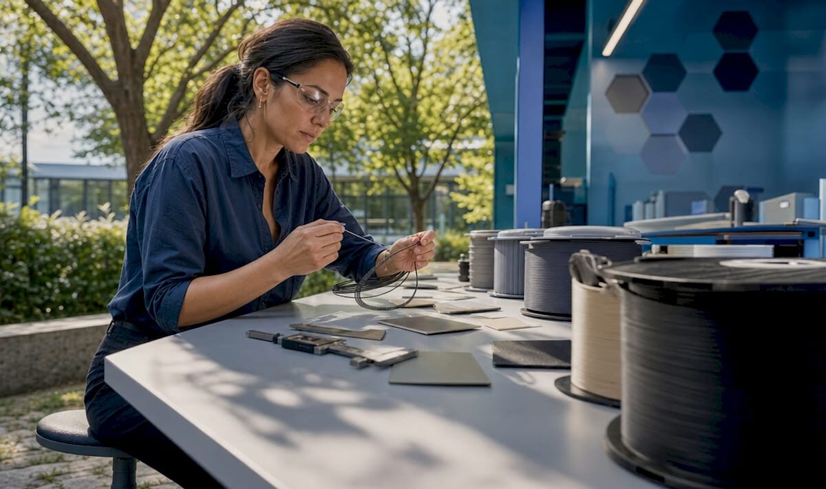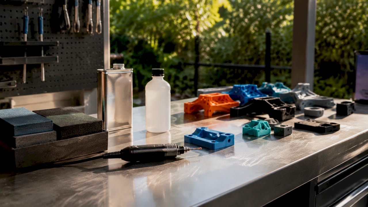
Technician inspects batch 3D printed parts

Batch 3D Printing: A Practical How-To Guide for 2026


TL;DR:

  • 3D printing is cost-effective for batch sizes up to 500 units, especially for complex geometries.
  • Preparing detailed design verification, proper material selection, and meticulous post-processing are essential for quality.
  • Scaling requires validation, central management, and risk mitigation through smaller sub-runs and redundancy.

Traditional manufacturing hits a wall when you need 50, 200, or 500 parts fast. Tooling costs for injection molding can exceed tens of thousands of dollars before a single part ships, and CNC machining queues stretch weeks when you need agility. 3D printing flips that equation, letting you run functional batches without custom tooling, long lead times, or minimum order commitments. This guide walks you through every stage of batch production with 3D printing, from early design decisions to post-processing and scaling, so you can move faster, waste less, and produce parts that actually perform.

Table of Contents

Key Takeaways

Point Details
Best for small to medium runs 3D printing shines in batch production for units below 1000, avoiding costly tooling.
Preparation is critical Successful batches depend on careful design, material choice, and spacing strategies.
SLS and MJF for durability These methods offer superior consistency and strength over FDM, making them ideal for functional parts.
Scale with caution Split large jobs into safer batches and document processes for better control and repeatability.

Understanding batch production in 3D printing

Batch production means manufacturing a defined quantity of parts in one or more coordinated print runs, rather than printing one-off or running continuous mass production. In the 3D printing context, a batch can be as small as 10 units or as large as several hundred, all produced with consistent settings, materials, and quality checks.

The question most engineers face is: when does 3D printing beat traditional manufacturing for batch work? The answer depends on volume, complexity, and tooling cost. 3D printing is cost-effective under 500 units, especially for complex geometries that would require expensive molds or multi-axis CNC fixturing. Above 1,000 units, injection molding typically wins on per-part cost, but you lose the flexibility to iterate designs mid-run.

For low-volume manufacturing tips that keep costs under control, the key advantage of 3D printing is eliminating setup costs entirely. No mold, no jig, no fixture. You change a file and reprint.

When 3D printing batch production makes sense:

  • Runs of 10 to 500 units with design iteration expected
  • Complex internal geometries that molds cannot produce
  • Tight launch timelines with no room for tooling lead times
  • Custom or personalized variants within the same batch
  • Bridge production while waiting for injection mold tooling

Here is a quick comparison to frame your decision:

Factor 3D printing Injection molding CNC machining
Setup cost Near zero $5,000 to $50,000+ Medium to high
Best volume Under 500 units Over 1,000 units 1 to 200 units
Design changes Instant file update Mold rework required Re-program needed
Geometry complexity Excellent Limited by draft angles Limited by tool access
Lead time Hours to days Weeks to months Days to weeks

Hybrid workflows, combining additive manufacturing with light CNC finishing, often deliver the best results for functional batches needing tight tolerances. Knowing which 3D printing type to choose for your part requirements is the first real decision.

Engineer measuring 3D printed part at bench

Mapping out your batch: Preparation essentials

Understanding the benefits is only useful if you prepare correctly. Here’s what you need for a smooth batch production run.

Before you start printing, your design files and production plan need to be solid. A single upstream error, like a wall thickness below the printer’s reliable minimum, can ruin an entire tray of parts. Designing reliable 3D prints starts with checking tolerances, adding consistent wall thicknesses, and minimizing overhangs that require dense support structures.

Pre-batch preparation checklist:

  • Verify all STL or 3MF files are watertight with no mesh errors
  • Set tolerances to account for your material’s shrinkage rate
  • Orient parts to minimize support material and maximize layer strength
  • Choose material based on mechanical, thermal, and surface finish requirements
  • Confirm build volume fits your batch without overcrowding
  • Test one or two parts before committing the full batch

Material selection is often underestimated. PLA works for display prototypes but fails under heat or load. PETG balances ease of printing with decent mechanical properties. Nylon and PA12 powders suit functional end-use parts. Your post-processing plan also influences material choice, since some materials sand, dye, or machine better than others.

For FDM batch runs, sequential printing over simultaneous is more reliable, especially on multi-nozzle or single-head machines. Keep 5 to 10mm spacing between parts, enable Z-hop at 0.2 to 0.4mm to avoid knocking parts over, and turn on combing to minimize stringing across the build plate. For powder-bed processes like SLS, the powder acts as a self-supporting medium, so you can stack and nest parts freely in the Z direction.

Setting FDM batch SLS/MJF batch
Part spacing 5 to 10mm 2 to 5mm
Support strategy Minimized but required Not required
Z-hop 0.2 to 0.4mm Not applicable
Nesting 2D build plate Full 3D volume

If you use 3D scanning to verify existing parts or reverse-engineer components, integrating high quality 3D scan data into your pre-production workflow reduces dimensional errors before the first layer prints.

Pro Tip: Design every part in a batch to share the same orientation on the build plate. Consistent orientation means consistent layer lines, consistent strength, and consistent surface finish across every unit.

Executing the batch production process: Step-by-step guide

Prepping your batch is only half the equation. Now, let’s walk through a reliable execution plan.

  1. Slice and nest your files. Use your slicer’s auto-arrange or manual layout to maximize density without crowding. Review the 3D preview for collisions or thin unsupported sections.
  2. Validate machine state. Check bed adhesion surfaces, nozzle condition, filament moisture content for FDM, or powder age for SLS/MJF. A contaminated bed ruins the entire tray.
  3. Run a single-unit test print. Before committing 200 parts, confirm one unit meets dimensional and visual specs. This step saves hours.
  4. Start the batch and monitor early layers. The first three to five layers predict 90% of batch failures. Stay close or use a camera feed to catch adhesion issues early.
  5. Log runtime parameters. Record temperature, humidity, print speed, and any deviations. This data is your diagnostic tool for the next run.
  6. Handle mid-run adjustments carefully. Some slicers and firmware allow live flow rate or temperature tweaks. If you adjust, document it immediately.
  7. Remove and label each batch tray. Traceability matters. Label each tray with date, material lot, and settings version before post-processing begins.

“MJF PA12 tensile strength reaches approximately 46 MPa and withstands 100,000 cycles with under 16% stiffness loss, while SLS offers better batch-to-batch reproducibility. FDM remains limited by layer anisotropy and delamination risk for functional batch parts.”

For teams printing quality prototypes alongside functional parts, keeping separate print queues by material and purpose prevents cross-contamination of settings and priorities.

Pro Tip: Log every print run in a simple spreadsheet: date, machine, material lot, settings file version, and any anomalies. When a defect appears in batch 47, you will know exactly what changed from batch 46.

For teams scaling to print farm operations, 3D printing on demand with distributed printers requires centralized file management and consistent firmware versions across all machines to avoid output variation.

Post-processing and quality verification: What to check

You’ve completed your batch run, but production isn’t finished until you ensure every part meets your standard.

Post-processing is where batch efficiency either compounds or collapses. Rush it, and defects slip into the supply chain. Over-engineer it, and you lose the cost advantage of additive manufacturing entirely. The goal is a structured, repeatable QA process scaled to your batch size and part function.

Core post-processing steps by part type:

  • Support removal: Remove carefully with flush cutters or media blasting for SLS/MJF parts. Inspect support interfaces for surface damage.
  • Surface finishing: Sand, bead blast, or vapor smooth depending on cosmetic requirements and material.
  • Dimensional check: Measure critical features with calipers, CMM, or go/no-go gauges. Focus on mating surfaces, bores, and thread engagement zones.
  • Mechanical inspection: Flex-test clips, torque-test fastener points, or pull-test adhesive joints where functional performance is critical.
  • Cosmetic review: Check for layer delamination, warping, color inconsistency, or surface voids under diffuse lighting.

For production batches of 300 to 800 units in industrial device applications, MJF suits mid-volume functional runs while SLS delivers tighter batch-to-batch reproducibility. FDM is a real risk for parts that see mechanical stress or cyclic loading.

Sampling strategy matters. You do not need to inspect every unit in a 500-part batch. Use AQL (Acceptable Quality Level) sampling tables to select a statistically valid sample size. For critical functional parts, inspect 100%.

Infographic showing batch 3D print QA basics

Printer type Typical post-processing QA priority
FDM Support removal, sanding Delamination, warping
SLS Powder removal, bead blast Dimensional accuracy
MJF Powder removal, dyeing Surface consistency
Resin UV cure, support removal Brittleness, warping

For insight into functional part fabrication requirements across different industries, matching your QA process to the part’s end use is the fastest way to keep costs reasonable without cutting corners.

Scaling up and optimizing your batch production workflow

After validating one batch, you may need to ramp up production. Here’s how to scale efficiently without sacrificing quality.

  1. Validate before scaling. Run two or three small batches with full QA before increasing volume. Undetected issues multiply fast at scale.
  2. Introduce print farms gradually. Add machines in pairs, not all at once. Validate output from each new machine against your baseline before routing production jobs to it.
  3. Centralize file and settings management. Use a version-controlled repository for all print profiles. A rogue settings file on one machine can corrupt an entire production run.
  4. Automate where the ROI is clear. Automated bed leveling, filament runout sensors, and camera monitoring pay back quickly. Full robotic part removal is worth evaluating for very high-volume FDM farms.
  5. Build redundancy into your schedule. Plan for one machine to be down at any time. If your schedule cannot absorb one printer being offline, you are understaffed on capacity.

Breaking mega-batches into smaller sub-runs reduces catastrophic failure risk and makes QA more manageable. If one sub-run fails, you lose a fraction of your day, not your entire production week. MJF and SLS isotropic properties make them the natural choice for functional batch scaling, but secondary machining remains necessary for features requiring tolerances tighter than ±0.2mm.

For teams evaluating custom batch printing jobs, the decision between in-house scaling and outsourcing often comes down to utilization rate. Owning printers makes sense above 60 to 70% utilization. Below that, a service bureau is almost always more cost-effective. Staying current on 3D printing trends shaping manufacturing helps you time capital investments in new equipment wisely.

Pro Tip: Split any batch larger than 100 units into at least two separate print runs on separate machines. This gives you a live comparison of output consistency and a safety net if one machine develops a problem mid-run.

A practical perspective: What most guides miss about batch 3D printing

Most batch production tutorials focus on filling the build volume. Pack the tray, maximize machine time, reduce cost per part. We have seen that logic backfire more than once. When a tray of 80 parts fails at hour 14 because one part warped into the print head, you lose all 80 parts and the machine time. Two trays of 40 parts, run sequentially, would have saved at least half the output.

The real discipline in batch 3D printing is not optimization. It is risk management. Experienced production teams prioritize traceability, redundancy, and process documentation over raw throughput. They know which failures repeat and why, because they logged the data from the last 30 runs.

Post-processing and QA also take longer than engineers typically budget. A 10-hour print run can generate 6 to 8 hours of support removal, inspection, and finishing work. That hidden labor cost often makes on-demand custom parts from a service provider more economical than in-house production for periodic batch needs.

Hybrid workflows, additive for complex geometry and traditional machining for tight tolerances, consistently outperform pure additive in SME environments. The engineers who figure that out early stop chasing tolerances the printer cannot reliably hold and start designing around the process instead.

Ready to streamline your batch production?

Armed with these strategies, you may be ready to print smarter, not harder. If you want to put these best practices into action even faster, here’s where to start.

https://cc3dlabs.com

At CC 3D Labs, we specialize in exactly this kind of work: prototypes, functional parts, and low- to mid-volume 3D printing services for product developers and manufacturers who need reliable output without the overhead of in-house print farms. Whether you want to explore what 3D printing can do for your specific parts or you are ready to place an on-demand batch printing order, our team near Philadelphia is set up to support your production goals with fast turnaround and real quality control.

Frequently asked questions

What is batch production in 3D printing?

Batch production in 3D printing means manufacturing multiple identical or varied parts in one or more print runs, optimizing efficiency and costs without needing complex tooling. It is cost-effective for runs under 500 units, especially for complex geometries.

How do I avoid failed parts during batch 3D printing?

Split large jobs into smaller batches, use print farms for redundancy, and log each print’s settings to catch recurring errors early. Breaking mega-batches into sub-runs limits how much output you lose when something goes wrong.

Which 3D printing method is best for functional parts in batches?

SLS and MJF offer the best strength and batch consistency for functional parts. MJF PA12 reaches approximately 46 MPa tensile strength and handles high-cycle loading well, while FDM is less reliable for stressed or high-cycle use.

Is 3D printing suitable for high-volume manufacturing?

3D printing is best for batches under 1,000 units. For higher volumes, injection molding outperforms 3D printing on per-part cost, though tooling investment and lead time are significantly higher.

Technician setting up 3D scanning workspace

How to scan objects for 3D printing: accurate steps


TL;DR:

  • Precise scanning requires proper equipment, environment, and preparation to avoid errors.
  • Post-processing and environment control are critical for achieving accurate, printable 3D models.
  • Expert support enhances consistency and quality in complex scan-to-print workflows.

Imagine delivering a prototype to a client only to discover it fits 0.3 mm off because the original scan drifted during capture. That single error can mean scrapped parts, missed deadlines, and a project budget that spirals fast. For product developers and engineers working with physical references, the gap between a rough scan and a precise, print-ready model is where most time gets lost. This guide walks you through every stage of the scan-to-print workflow, from choosing the right scanner to fixing mesh errors before your file ever touches a printer, so you can stop guessing and start shipping accurate parts.

Table of Contents

Key Takeaways

Point Details
Choose the right scanner Structured light and laser scanners deliver sub-0.1 mm precision for prototypes, while photogrammetry is suitable for large or textured parts.
Prep surfaces meticulously Using matte spray on challenging materials boosts scan accuracy and reliability significantly.
Follow a structured workflow Careful calibration, multi-angle coverage, and steady capture prevent tracking loss and ensure clean scan data.
Fix and convert mesh for printing Cleaning, aligning, and exporting the mesh as watertight STL or converting to CAD solids is essential before 3D printing.

Essential equipment and prerequisites for 3D scanning

Before you place a single object on a turntable, understanding your scanner options saves you from buying tools that don’t match your tolerance requirements.

Three primary methodologies cover the majority of professional use cases: structured light scanning, laser triangulation, and photogrammetry. Each one has a different cost profile, accuracy ceiling, and ideal application.

Method Typical accuracy Best use case Approx. cost range
Structured light ±0.01 to ±0.05 mm Small, high-detail parts $5,000 to $50,000+
Laser triangulation ±0.04 to ±0.15 mm Mid-size industrial parts $3,000 to $30,000
Photogrammetry ±0.1 to ±1.0 mm Large objects, low budget $200 to $5,000

Industrial benchmark data confirms that portable handheld units and desktop scanners occupy very different accuracy tiers, and choosing between them depends entirely on your part size and tolerance spec.

Beyond the scanner itself, you need a short list of supporting tools:

  • Matte scan spray or powder for reflective or dark surfaces
  • Calibration targets or panels supplied by your scanner manufacturer
  • Motorized turntable for consistent multi-angle desktop captures
  • Compatible scan software such as VXelements, Artec Studio, or Meshlab
  • Stable platform free from vibration (rubber-padded table or anti-vibration mat)

Workspace setup matters as much as hardware. Fluorescent overhead lighting creates inconsistent shadows, so diffuse LED panels or softboxes give you repeatable illumination. A high-quality scan process also demands that scanner software and your workstation GPU are matched, since processing dense point clouds in real time is computationally demanding.

Pro Tip: Always verify software compatibility before purchasing a scanner. Some units lock you into proprietary platforms that limit your export options later.

Preparing objects and environment for accurate scans

Once you have the right gear, precise preparation is critical. Skipping prep is the single most common reason engineers get misaligned or incomplete scan data.

Follow this preparation sequence before every scan session:

  • Clean the part thoroughly. Dust, oils, and residue create false surface details that corrupt mesh geometry.
  • Assess the surface finish. Shiny, dark, or featureless surfaces need treatment before scanning begins.
  • Apply matte spray where needed. Matte spray is crucial for reflective, dark, or featureless objects because it diffuses light and adds trackable texture the scanner’s algorithms can lock onto.
  • Place tracking markers. Adhesive dot markers help handheld scanners maintain registration across large or low-feature surfaces.
  • Position the object at waist height. Awkward angles during scanning introduce operator-induced motion blur.

Environmental habits deserve equal attention. Avoid scanning near windows where sunlight shifts during a session. Direct sun introduces infrared interference that confuses structured light and laser sensors. Keep ambient temperature stable because thermal expansion on metal parts can introduce measurable dimensional drift over a long session.

Proper calibration and controlled lighting are non-negotiable for mitigating environmental variables that degrade scan quality. Run your calibration routine at the start of every session, not just at setup.

Engineer calibrates scanner under controlled lighting

For especially challenging parts, follow a step-by-step scanning guide to walk through each environmental check systematically. You can also reference the 3D scanning checklist and the design accuracy and prototyping guide to build a repeatable pre-scan protocol for your team.

Pro Tip: Prepping challenging surfaces correctly can boost first-pass scan success rates by 80 to 90%, according to professional scanning technicians. That time investment pays back immediately by eliminating re-scans.

Step-by-step scanning process for optimal results

With the setup complete, let’s break down the end-to-end scanning workflow. Skipping steps here is how tracking errors and misaligned meshes happen.

  1. Run calibration. Use the manufacturer-supplied calibration target. Never skip this, even if the scanner was calibrated yesterday.
  2. Set scan resolution and mode. Choose your target resolution based on part size and feature complexity, not maximum settings.
  3. Begin with a reference pass. Capture the dominant geometry first before moving to tight features and recesses.
  4. Maintain 30 to 60% frame overlap. Scanning with frame overlap between passes is the foundation of accurate alignment and clean mesh fusion.
  5. Pan steadily at consistent speed. Rapid movements cause motion blur; slower passes give the scanner time to lock geometry.
  6. Perform multiple passes at different angles. Top, side, and underside passes together fill in occlusions that a single sweep misses.
  7. Review the point cloud in real time. Most modern scanners show live feedback; stop and re-scan if a zone looks sparse.
  8. Export the aligned scan. For direct 3D printing, STL is suitable for replica output; for parametric engineering edits, you need a CAD solid.
Issue Likely cause Fix
Tracking loss Too-fast movement or featureless surface Slow down, add markers
Mesh holes Occlusion from single-angle pass Add underside and angled passes
Misalignment Insufficient overlap Increase to 50% frame overlap
Noise/artifacts Reflective surface or ambient light Apply matte spray, reduce ambient light

For teams running production volume scans, the scanning lab overview shows how professional setups handle repeatable multi-pass workflows at scale.

Pro Tip: If tracking is lost mid-scan, return the scanner to the last well-registered zone and slowly re-establish lock before continuing. Trying to power through tracking loss creates permanent misalignment in that section.

Advanced techniques and troubleshooting challenging parts

Even with a good process, tricky surfaces can derail a scan. Certain materials and geometries require specific tactics, and knowing them in advance saves a full rescan.

Infographic showing causes and solutions for scan issues

Reflective metals and chrome parts: Apply a thin, even coat of matte scan spray. The coating is removable and adds the texture contrast that laser and structured light sensors need to resolve geometry accurately.

Transparent or semi-transparent objects: Scan the part before final finish, or lightly scuff the surface with fine-grit media to create diffuse reflectance. Transparent surfaces return no usable data without treatment.

Dark or black parts: Different materials and surface finishes require matte spray, markers, or modified lighting to give the sensor something to track. Black absorbs near-infrared light, which is exactly what most scanners emit.

Complex internal geometry and deep recesses: You cannot capture blind holes or undercuts from a single orientation. Plan your scan order to capture recesses at oblique angles before surrounding geometry blocks access.

Tracking loss is the leading cause of scan failure. Pausing when lock degrades and overlapping back onto known geometry maintains registration far better than continuing through drift.

Failures from tracking loss are preventable with proper overlap habits. Always pause, re-establish your lock zone, then continue.

For a deeper look at how surface prep and environment interact, the achieve quality scan resource covers the full process. When your scan feeds directly into a product iteration, also review designing reliable prototypes to align your scan strategy with downstream print requirements.

Pro Tip: Always use matte spray in a well-ventilated area. Many scan sprays contain aerosol propellants and solvents that require ventilation and appropriate PPE.

Post-processing: Converting scans to printable models

Once you have scan data, refining it is crucial to get professional results. Raw point clouds are not print-ready files; they need cleaning, alignment, and export in the right format.

Here is the standard post-processing sequence:

  1. Import and align multiple scan passes. Use software like Meshlab or your scanner’s native platform to register scans to a common coordinate frame.
  2. Fuse passes into a unified mesh. Merging overlapping point clouds removes duplicate geometry and fills minor gaps.
  3. Run mesh repair. Identify and fix non-manifold edges, holes, and inverted normals that would cause print failures.
  4. Decimate intelligently. Reduce polygon count without losing critical feature detail, especially on flat surfaces where dense meshes waste file size without benefit.
  5. Export in the correct format. Choose STL or OBJ for direct printing; choose STEP or IGES when the file needs to go into a CAD environment for parametric editing.

The format choice is not cosmetic. Scan meshes must be converted to CAD solids for genuine engineering edits; direct STL prints work fine for replicas but offer no parametric flexibility.

A print-ready mesh should meet these criteria:

  • Watertight: No open boundaries or holes in the surface
  • No non-manifold edges: Every edge shared by exactly two faces
  • Correct face normals: All faces pointing outward
  • Appropriate polygon density: Balanced for file size and feature resolution

For teams that need CAD modeling services to take a scan mesh into a fully editable solid model, that process is distinct from basic STL cleanup. Review the CAD file format workflow to understand which format fits your specific pipeline before you commit to an export.

Why real-world 3D scanning is more nuanced than the manuals say

Every scanner manufacturer publishes impressive accuracy specs. What those specs rarely tell you is that they were measured under laboratory conditions that most production environments cannot replicate. Temperature fluctuations, vibration from nearby equipment, and even a vent blowing air across a part can push a scan from spec-grade to unusable.

The engineers who consistently get great results are not the ones with the most expensive scanners. They are the ones who treat environmental control as their first priority and accept that scanning is an iterative process, not a one-shot event. Hybrid approaches, where a scan establishes the base geometry and CAD modeling corrects critical tolerances, routinely outperform pure scan workflows on engineering parts.

The real-world scan accuracy insights we have gathered from actual production projects show that repeatability across sessions matters far more than peak accuracy on a single scan. A process that reliably delivers ±0.08 mm every time beats a workflow that occasionally hits ±0.03 mm but drifts unpredictably. Build a repeatable process first, then optimize for precision.

Achieve pro-level 3D scans with CC3DLabs expertise

For teams ready to streamline their scan-to-print process, expert support makes all the difference. Getting a clean, production-ready scan file consistently requires more than good equipment; it takes a calibrated workflow, trained operators, and post-processing discipline.

https://cc3dlabs.com

At CC3DLabs, our 3D scanning lab handles the full pipeline from physical object to print-ready or CAD-ready file, including metrology-grade scanning for precise reverse engineering. Whether you need a single prototype scan or batch part documentation, we deliver high-quality scan results with fast turnaround. Our CAD modeling and reverse engineering team can take your scan mesh and rebuild it as a fully editable solid model ready for engineering changes. Request a free estimate and let us handle the precision work.

Frequently asked questions

What is the best scanner for detailed small parts?

Structured light desktop scanners are typically the best choice for small, high-detail parts, delivering accuracy as fine as ±0.01 to ±0.05 mm. Their controlled projection patterns resolve tight features that handheld units can miss.

How do I scan shiny or transparent objects accurately?

Apply matte scan spray to diffuse the surface and use angled or dome lighting to reduce reflections. For transparent parts, scan before final finish or lightly scuff the surface to create diffuse reflectance.

Can I 3D print directly from scanned meshes?

Yes, if the mesh is watertight and error-free you can print directly. However, convert to a CAD solid when you need engineering edits or parametric design flexibility that STL cannot support.

What is the typical accuracy of handheld laser scanners for industrial parts?

Handheld laser scanners typically reach accuracy levels of ±0.04 to ±0.15 mm, which covers the majority of prototyping and spare part replacement needs without requiring a fixed desktop setup.

Engineer testing 3D printed prototype hinge

Why Durable 3D Printed Parts Matter for Prototyping


TL;DR:

  • Durable 3D printed parts enable multiple realistic test cycles, reducing time and cost.
  • Material choice and design orientation are crucial for achieving mechanical durability.
  • Increased durability expands design possibilities and improves prototype credibility in development.

Part failure doesn’t just break a prototype. It breaks schedules, burns through budget, and erodes confidence in the entire development process. Many engineers still assume that 3D printed parts are only good for visual mockups, reserving “real” structural testing for machined or injection-molded components. That assumption costs teams time and money. Durable 3D printed parts have fundamentally changed what’s possible in functional prototyping and low-volume production. This guide breaks down why durability is central to successful product development, what actually makes a printed part durable, and how to apply that knowledge across your engineering workflow.

Table of Contents

Key Takeaways

Point Details
Durability ensures success Durable 3D printed parts speed up development and reduce costly failures.
Material and design matter Choosing the right material and thoughtful design directly impacts durability and performance.
Complex features, real validation Durable parts allow for complex mechanisms and repeated, realistic testing.
Broad application range From rapid prototypes to functional parts, durability unlocks true value in 3D printing.

The cost of weak prototypes: Why durability drives development

Weak prototypes don’t just fail. They mislead. When a snap fit breaks under light load, or a hinge cracks after three cycles, you’re not learning about your design. You’re learning about the limits of your material choice. That distinction matters enormously in engineering.

Consider what happens when a prototype fails mid-test. The team halts. You log a failure that may or may not reflect a real design issue. You reprint, wait, and re-run the test. In a tight development cycle, this sequence repeats enough times to push back launch dates by weeks. For startups or contract manufacturers under deadline pressure, that’s not a minor inconvenience.

Durable prototypes carry their weight across multiple test cycles. They allow teams to:

  • Run repeated mechanical load tests without part replacement between cycles
  • Validate snap fits, living hinges, and press fits under realistic conditions
  • Compare design iterations side by side without variables introduced by part failure
  • Ship samples to stakeholders or end-users for field feedback
  • Generate reliable data for engineering sign-off

Understanding what 3D printers can make in terms of functional geometry is the first step toward choosing prototyping methods that actually support your testing protocol.

Here’s the part most teams overlook. Durable 3D printed parts don’t just survive more tests. They expand design freedom by enabling complex geometries, internal features, and moving mechanisms, which can deliver more engineering value than raw strength alone, as Stratasys functional prototyping guidance notes.

“The prototype that holds up through 200 test cycles tells you something real. The one that fails on cycle four tells you almost nothing useful.”

There’s a credibility dimension here too. When product development teams present durable functional prototypes to stakeholders or investors, those parts carry weight. A flimsy visual model gets polite nods. A part that clicks, flexes, seals, or rotates exactly as intended generates real confidence. Teams that prioritize designing reliable 3D prints from the start avoid the credibility gap that comes from presenting fragile early-stage models as proof of concept.

Durability isn’t a premium add-on in prototyping. It’s a prerequisite for any data you plan to trust.

What makes a 3D printed part durable?

Durability in 3D printing isn’t just about tensile strength. It’s a combination of mechanical toughness, thermal resistance, fatigue performance, and how well the part geometry supports load distribution. A part can be made from a strong material and still fail early if the design undermines it.

Technician adjusting 3D printer with functional part

3D printing enables mechanically functional prototypes that support realistic validation, going well beyond what aesthetic models can prove. But getting there requires controlling several variables simultaneously.

Material selection is the most visible factor. Here’s how common filament-based materials compare:

Material Strength Toughness Heat resistance Best use case
PLA Moderate Low Low Visual prototypes, low-stress parts
ABS Good Moderate Moderate Functional housings, structural parts
PETG Good High Moderate Snap fits, food-safe parts, enclosures
Nylon High Very high High Load-bearing, wear components
CF composites Very high Moderate High Structural, aerospace-grade parts

For best materials for durability, PETG and Nylon consistently outperform PLA in real-world functional tests.

Design factors often matter just as much as material choice. The key variables include:

  • Wall thickness: Too thin and you lose structural integrity; too thick and you introduce internal stress during cooling
  • Infill pattern and density: Gyroid and honeycomb patterns distribute load more effectively than rectilinear at the same density
  • Build orientation: Parts printed with load-bearing walls aligned to the Z-axis often perform differently than those oriented horizontally
  • Feature geometry: Rounded interior corners reduce stress concentration points that cause crack propagation

Pro Tip: When designing for durability, orient your most critical stress surfaces perpendicular to the build plate. Layer adhesion is typically the weakest point in FDM parts, so controlling orientation controls where failure is least likely to happen.

Knowing which 3D printing type to choose for your application unlocks a much sharper set of decisions than just picking the cheapest option available.

3D printed durability in practice: Unlocking new design freedoms

Durability becomes most interesting when it stops being a constraint and starts being a capability. When your printed part can survive real use, your design space expands dramatically.

Durable 3D printed parts expand design freedom by enabling complex internal features and mechanisms, facilitating realistic validation that traditional manufacturing can’t match at prototype scale.

Here are five practical design freedoms that durable 3D printing unlocks for engineers:

  1. Integrated snap fit assemblies that click and unclick through hundreds of cycles, letting you validate engagement force and fatigue life before tooling
  2. Living hinges printed directly into the part, reducing assembly complexity and testing hinge performance in context
  3. Internal fluid channels that allow functional fluid routing in manifolds, housings, or medical devices without secondary machining
  4. Lightweight lattice structures that maintain stiffness while cutting mass, useful in aerospace and wearable applications
  5. Embedded feature testing where threads, inserts, and bosses are built into the same part and tested as an integrated system

Pro Tip: Use durable prints to do tolerance stack-up testing before committing to production tooling. Print your assembly at multiple tolerance offsets and test which combination gives the best fit and function. It costs a fraction of what a tooling revision does.

Infographic with durability qualities and prototype benefits

The time and cost advantage of this approach is significant. Consider a simplified comparison:

Scenario Traditional CNC prototype Durable 3D printed part
Lead time 2 to 4 weeks 1 to 3 days
Design iteration cost High (each change = new setup) Low (file update + reprint)
Complex geometry Limited by tooling access No restriction
Functional testing readiness Immediate after machining Immediate after print

Browsing real-world filament prototype examples shows how these advantages play out across industries, from consumer electronics enclosures to industrial jigs.

If you’re evaluating whether 3D printing can handle your next project, exploring custom prototype options early in the scoping phase avoids rework later.

When and why durability matters most: High-stakes applications

Not every prototype needs to be engineered for maximum durability. But when it matters, it really matters. These are the scenarios where part failure carries serious consequences.

Durable 3D printed parts support fully functional prototypes that reduce risk before committing to expensive production tooling. That risk mitigation is especially critical in:

  • Jigs and fixtures: These parts are used repeatedly on the production floor. A jig that breaks after 20 uses creates quality control gaps and line stoppages.
  • Medical device prototypes: Regulatory submissions often require proof of functional performance. Fragile parts can’t generate that evidence.
  • Aerospace spare and support parts: Weight matters. Durability matters. These requirements have to coexist.
  • Automotive fit-and-function testing: Clearances, assembly sequences, and part interactions are validated at this stage. A broken test piece delays the entire validation protocol.
  • Field-use replacement parts: When the original component is discontinued, a durable 3D printed replacement needs to perform, not just look right.

“Every week spent reprinting a failed jig is a week the production line is working around a problem that should already be solved.”

For teams navigating limited production quantities, tips for low-volume manufacturing provide a practical framework for matching durability requirements to production strategy.

The pattern across all these applications is the same. Durable parts create reliable data. Reliable data creates confident decisions. And confident decisions reduce the cost and risk of moving from prototype to production.

A practical perspective: Stop underestimating durable 3D prints

Here’s what the data doesn’t fully capture. Many engineering teams still treat 3D printing as a visual communication tool. They print a model to show management, not to test mechanics. That habit is expensive, and it’s rooted in outdated assumptions about what printed parts can handle.

The teams getting the most value from 3D printing today are evaluating durability at the project scoping stage, before the first file is sent to print. They’re asking which mechanisms need to survive how many cycles, what load conditions apply, and what material properties are actually required. That thinking shapes every decision downstream.

The uncomfortable truth is that teams who focus only on cheap, fast visual prototypes often discover their design flaws at the worst possible time, during final validation or, worse, after tooling has been cut. Switching to durable functional prototypes earlier in the process catches those flaws when changes are still cheap.

For a sharper understanding of how this fits into the broader development cycle, rapid prototyping insights provide a solid foundation for rethinking your prototyping strategy from the ground up.

Discover durable 3D printing solutions for your next project

If this article has shifted how you think about durability in your prototyping workflow, the next step is putting that thinking into practice.

https://cc3dlabs.com

At CC 3D Labs, we specialize in custom filament-based 3D printing for engineers and product developers who need parts that actually perform. From single functional prototypes to small batch production runs, our professional 3D printing services are built around accuracy, material expertise, and fast turnaround. Explore on-demand prototype printing to get an estimate on your next part, or sharpen your technical vocabulary with our 3D printing terminology guide before your next project kickoff.

Frequently asked questions

What defines a ‘durable’ 3D printed part?

A durable 3D printed part can withstand mechanical stress, repeated use, and real-world conditions without failing. Functional validation with active mechanisms and stress points is the real test of durability, not just static load capacity.

How does durability impact prototype testing?

Increased durability allows for repeated, realistic testing cycles and accelerates design iteration. Mechanical testing and validation of complex features become far more reliable when the part itself isn’t the variable that fails.

Which 3D printing materials are most durable?

ABS, PETG, Nylon, and engineering composites are leading choices for mechanical durability. Material choice directly dictates functional performance and the mechanical properties your part can deliver under load.

Are durable 3D prints only for industrial applications?

No. Durable parts are valuable for real-world applications beyond visual prototypes, including custom end-use parts, low-volume manufacturing, field repairs, and consumer product development across many sectors.

Technician reviewing 3D printed prototype at workshop desk

Why Print Accuracy Is Critical for 3D Prototyping


TL;DR:

  • Print accuracy measures how closely a 3D printed part matches CAD design dimensions.
  • Layer height, print speed, material shrinkage, and slicer calibration are key factors affecting accuracy.
  • Incorporating process control and topology optimization enhances reliability and reduces dimensional errors.

A single 0.2mm dimensional error seems insignificant on paper. In practice, it can mean a snap-fit assembly that won’t close, an engineering jig that wobbles under load, or a costly round of reprints that blows your project timeline. For product developers and manufacturers, this is not a hypothetical situation. It happens more often than most teams want to admit. The misconception is that 3D printing is rapid and “close enough” by nature. But when you’re validating a functional prototype or preparing for short-run production, close enough is never actually good enough. This guide explains what print accuracy really means, what drives it, and how to build it into every stage of your workflow.

Table of Contents

Key Takeaways

Point Details
Print accuracy defined Print accuracy is how closely your 3D part matches your design—critical for fit and function.
Settings matter most Layer height, print speed, and material choice determine accuracy much more than printer brand.
Material choice impacts results PLA and PETG offer better dimensional stability than ABS, reducing warping and shrinkage.
Advanced methods boost reliability Using topology optimization and process-aware tools produces more consistent and dependable prints.

What does print accuracy mean in 3D printing?

With the stakes clear, let’s define exactly what print accuracy means and why it isn’t just another technical buzzword.

Print accuracy describes how closely a finished 3D-printed part matches the original design dimensions in your CAD file. If your model calls for a 50mm hole and the printed result measures 49.6mm, you have an accuracy gap. That gap matters enormously once parts need to fit together, pass inspection, or meet a functional specification.

Infographic showing print accuracy essentials and results

It helps to distinguish accuracy from two related concepts. Precision refers to repeatability, meaning how consistently a printer reproduces the same result across multiple runs. Resolution refers to the smallest detail the printer can physically produce, typically expressed in microns. A printer can have high resolution but poor accuracy if it consistently prints features that are the wrong size. A machine can be precise but inaccurate if every part comes out 0.3mm too wide, every single time.

Why does a 0.2mm error wreck a snap-fit prototype? Because snap-fits operate within tight elastic deformation windows. Even a slight oversize on a cantilever arm can prevent engagement entirely. For engineering jigs used to hold, align, or guide other components, dimensional deviation means the jig introduces rather than eliminates error into your process.

Several variables directly control how accurate a print turns out:

  • Layer height: Layer height most significantly affects width and height errors in printed parts
  • Print speed: Faster movement reduces material control and increases deviation
  • Bed leveling: An uneven bed creates first-layer inconsistencies that propagate upward
  • Material shrinkage: All thermoplastics contract as they cool, some more than others
  • Nozzle temperature: Too low causes under-extrusion; too high causes material spread
  • Slicer calibration: Incorrect extrusion multiplier settings skew all feature sizes

Understanding the right 3D printing terminology before you start a project saves time and prevents costly assumptions.

Pro Tip: Before committing a design to a batch run, always compare your CAD tolerances to the documented capability of the printer and material you plan to use. A printer rated for ±0.2mm tolerance should never be trusted for a part that requires ±0.05mm fits without prior test prints.

Major factors that impact print accuracy

Now that it’s clear what accuracy means, let’s see what actually drives accurate and inaccurate results in 3D printing.

Empirical testing gives us the clearest answers. Research on FDM printing with PLA on a Prusa MK4 found that low speed, high temperature, and thin layers such as 20 to 40mm/s, 230°C, and 0.05mm layers delivered the best dimensional accuracy across tested parameters. That’s a meaningful benchmark for anyone running precision work.

Here’s how those findings translate into a practical parameter reference:

Parameter Optimal value for accuracy Effect of deviation
Layer height 0.05 to 0.10mm Thicker layers increase width and height error
Print speed 20 to 40mm/s Higher speed degrades material control
Nozzle temperature 230°C (for PLA) Lower temps cause under-extrusion and gaps
Bed temperature 60°C (for PLA) Incorrect temp causes warping and layer shift
Infill pattern Rectilinear or grid Complex patterns increase internal stress

Beyond settings, physical and process variables also play a major role:

  1. Design review: Check for features that exceed your printer’s capability before slicing
  2. Test piece: Print a calibration cube or representative feature before the full part
  3. Measurement: Use calipers to check test pieces against CAD dimensions before approving a run
  4. Slicer adjustment: Apply compensation values for known shrinkage or offset errors
  5. Post-processing review: Measure critical dimensions after any surface finishing or heat treatment

For guidance on matching material to tolerance requirements, the filament selection for precision guide covers real-world selection logic for demanding applications. If you’re still deciding between materials, see the breakdown of PLA, PETG, or ABS performance for functional parts.

Pro Tip: When dimensional accuracy is critical, reduce layer height and print speed before adjusting any other parameter. These two settings have the most direct and measurable impact on output fidelity.

Material selection and dimensional stability

Even with dialed-in settings, your material pick can make or break dimensional accuracy. Let’s see why.

Every thermoplastic shrinks as it transitions from molten to solid. The rate and consistency of that shrinkage determines how much the final part deviates from the design. Some materials are far more forgiving than others.

Engineer measuring 3D printed PLA and ABS blocks

Material Shrinkage rate Warping risk Best use cases
PLA Low (0.2 to 0.4%) Low Prototypes, display models, snap-fits
PETG Low to medium (0.3 to 0.5%) Low to medium Functional parts, mild chemical exposure
ABS High (0.7 to 1.6%) High Heat-resistant parts, post-processed components

Warping is the biggest accuracy threat from thermal behavior. Warping primarily comes from uneven cooling and shrinkage, and is best controlled with even cooling, adhesion aids, and choosing low-shrink materials like PLA or PETG when tolerances are tight.

“Warping doesn’t just ruin surface finish. It changes the geometry of a part in ways that are nearly impossible to correct after the fact. One curled edge on a mating surface can cascade into a full fit failure during assembly.” — Dimensional reliability perspective from materials engineering practice

Strategies to reduce warping and protect dimensional stability:

  • Use a heated enclosure for ABS and other high-shrink materials to slow and equalize cooling
  • Apply bed adhesion solutions such as glue stick, PEI sheets, or hairspray for better first-layer grip
  • Reduce part cooling fan speed for materials prone to layer delamination from rapid quenching
  • Orient parts to minimize large flat areas contacting the bed when using high-shrink filaments
  • Use brim or raft supports to anchor edge geometry during printing

One common overcorrection: teams add enclosures when printing low-shrink materials like PLA in cool environments. For most PLA prints, enclosures can actually trap heat and cause softening near the top layers. Know your material’s actual needs before defaulting to every countermeasure at once.

If you’re still narrowing down your options, the decision framework for choosing between PLA, PETG, and ABS breaks down dimensional trade-offs clearly. You can also explore what can be printed to see how material choice maps to real part applications.

Advanced methods: Topology optimization and process control

For truly reliable, repeatable parts, accuracy must extend beyond setup and materials. Here’s how modern approaches help.

Topology optimization is a computational design method that removes unnecessary material from a part while maintaining its structural performance. For 3D printing, it goes further than weight reduction. When the optimization algorithm incorporates the actual behavior of the printer, including how the print head deposits material and how bonding between layers works, the resulting geometry is fundamentally better suited to being printed accurately.

MIT’s advanced technique incorporates print head limitations and inter-layer bonding constraints directly into the topology optimization process, reducing deposition errors and making complex parts more reliable as a result. This is a significant shift from designing a part and hoping the printer handles it, to designing a part that the printer can actually execute with precision.

For manufacturers, the practical benefits are real:

  • Fewer failed prints: Designs that account for printer behavior fail less often mid-run
  • Less over-deposition: Optimized geometries reduce material buildup in corners and transitions
  • More repeatable outcomes: Process-aware designs perform consistently across multiple batches
  • Lower post-processing burden: Parts that print accurately need less sanding, filling, or rework
  • Better structural performance: Optimized designs maintain strength without compensating wall thickness

Process-aware slicing tools are also evolving. Modern slicer software increasingly allows users to input material behavior profiles so the tool can compensate for known shrinkage rates before the file is ever sent to print. Pairing this capability with topology-optimized geometry creates a workflow where accuracy is built in, not chased after.

For more on applying these principles to short-run work, the low-volume manufacturing tips resource covers batch consistency in detail. The designing for reliability guide addresses design-stage decisions that prevent dimensional problems before printing starts.

Why most teams underestimate print accuracy and how to shift your approach

Here’s the uncomfortable reality: most teams treat print accuracy as a printer problem, not a process problem. When a part comes out wrong, the instinct is to adjust a setting or switch machines. But accuracy failures are almost always systemic. They compound across decisions made in design, material selection, slicer setup, and even how results are measured and recorded.

Small errors are particularly dangerous because they feel correctable. A 0.3mm offset seems easy to absorb with a chamfer or a filed edge. But in a multi-part assembly, chain tolerance issues stack. What started as a minor gap at one interface becomes a structural misalignment two components later. By then, the cost of correction has multiplied.

Process discipline beats post-print correction every time. Log your print parameters, measure actual outputs, and compare them to design intent on every meaningful run. Never assume one batch mirrors the last. Filament lots vary, ambient temperature changes, nozzles wear. The low-volume accuracy approach we apply at CC 3D Labs reflects exactly this discipline.

Pro Tip: Keep a simple print log with layer height, speed, temperature, material lot, and measured output dimensions. Over time, this data reveals patterns that setting changes alone never will.

The teams that produce the most reliable prototypes are not the ones with the best printers. They’re the ones who treat accuracy as a non-negotiable standard at every stage, not an afterthought.

Get reliable prototypes with print-perfect accuracy

If you’re ready to leave inconsistency behind and prioritize accuracy, here’s how to take the next step.

At CC 3D Labs, we build dimensional accuracy into every project from file review through final inspection. Whether you need a single precision prototype or a short production run with tight tolerances, our team works through the exact settings and material choices covered in this guide on every job.

https://cc3dlabs.com

Explore our professional 3D printing services to see the full range of capabilities we bring to prototyping and functional part production. If you need parts fast, on-demand 3D prototyping gets you from file to finished part with zero guesswork on accuracy. And if you want to design for the best possible outcome from the start, our reliable print design tips give you a solid foundation before you ever send a file.

Frequently asked questions

What is the difference between print accuracy and precision?

Print accuracy differs from precision in a fundamental way: accuracy measures how closely a part matches the intended design dimensions, while precision measures how consistently those results repeat from one print to the next.

How much does layer height affect 3D print accuracy?

Layer height is the most significant factor for width and height errors in FDM prints. Thinner layers produce noticeably better dimensional fidelity, especially on features with fine detail or tight tolerances.

Why do some prints warp more than others?

Warping is primarily from thermal shrinkage and uneven cooling during printing. PLA and PETG shrink less than ABS, but proper bed adhesion, enclosure use, and cooling management can reduce warping across all common filament types.

How can topology optimization improve print reliability?

MIT’s technique incorporates real-world print constraints into the design optimization process, which reduces deposition errors and makes complex parts more structurally reliable. It shifts accuracy from a post-print correction problem to a pre-print design solution.