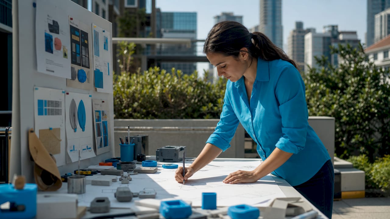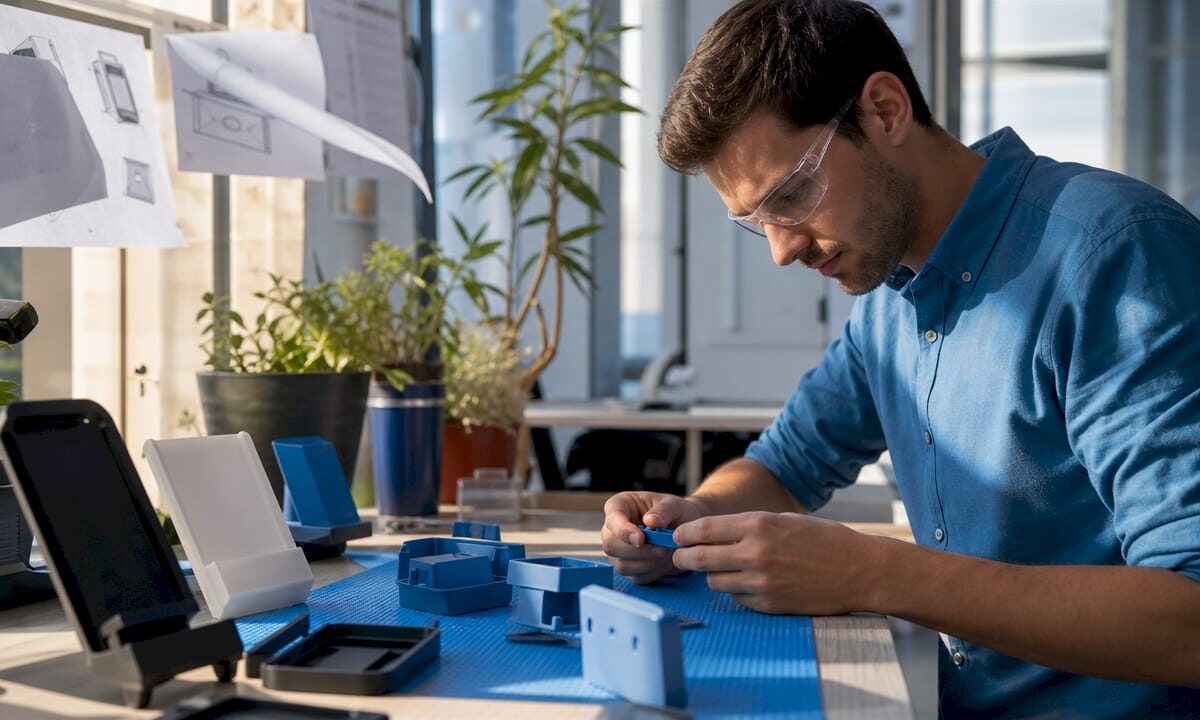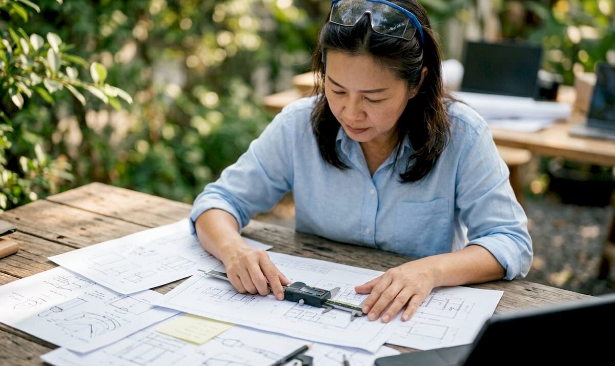
Engineer examining 3D printed prototype

Benefits of DFM in 3D Printing for Engineers


TL;DR:

  • Design for Manufacturability in 3D printing emphasizes designing parts to align with printer constraints, reducing print time, costs, and failures. Applying early DfAM principles enables part consolidation, improves strength through orientation, and accelerates prototypes, saving costs and time. Most failures result from late-stage design fixes; integrating DfAM from the start produces better products faster and lowers overall manufacturing expenses.

Design for Manufacturability, known in additive manufacturing circles as DfAM, is the practice of shaping a part’s geometry to work with a printer’s physical constraints rather than against them. The benefits of DFM in 3D printing are direct and measurable: faster print cycles, lower material costs, stronger parts, and fewer failed builds. Product developers who apply DfAM principles early catch problems before they become expensive. This article breaks down the top advantages, with specific techniques and data you can act on immediately.

1. How DFM reduces print time and material costs in 3D printing

Applying DFM principles to 3D printing cuts print times by 20–40% and lowers per-part costs by reducing support material and post-processing. That single change, designing geometry that holds itself up, is the highest-leverage move most engineers overlook.

The core technique is self-supporting geometry. Any surface angled greater than 45° from horizontal requires no support structures in FDM printing. Supports add print time, consume filament, and leave surface marks that require finishing work. Eliminating them cuts all three costs at once.

Specific geometry choices that reduce or eliminate supports:

  • Chamfers instead of horizontal overhangs. A chamfered edge at 45° prints cleanly. A flat horizontal ledge does not.
  • Teardrop holes instead of round holes. Circular holes printed horizontally sag at the top. A teardrop profile with a pointed apex is self-supporting.
  • Bridging spans under 5mm. Short horizontal gaps bridge cleanly without supports. Longer spans need either supports or a redesign.
  • Angled walls instead of vertical undercuts. Undercuts trap supports in hard-to-reach areas. Angled walls avoid the problem entirely.

Pro Tip: Design overhangs at 50° or steeper rather than exactly 45°. The extra margin accounts for real-world printer variation and reduces the chance of a borderline overhang failing mid-print.

Reducing post-processing effort is just as valuable as cutting print time. Support removal, sanding, and finishing can double the labor cost of a part. DfAM eliminates most of that work before the printer even starts.

2. Part consolidation and simplified assemblies

DfAM enables up to 90% part consolidation, reducing bill-of-materials complexity by 50–80% and eliminating assembly labor and mechanical fasteners. That is not a marginal gain. It changes the economics of a product line.

Overhead view of consolidated 3D printed parts

Traditional manufacturing forces engineers to split complex shapes into multiple pieces because molds and mills have geometric limits. 3D printing has no such constraint. A bracket, housing, and clip that once required three separate parts, three purchase orders, and an assembly step can print as one.

The practical benefits of consolidation follow a clear sequence:

  1. Fewer part numbers. Each eliminated component removes a purchase order, a supplier relationship, and a quality inspection point.
  2. No fastener costs. Screws, inserts, and adhesives add unit cost and assembly time. Consolidated parts need none.
  3. Reduced assembly risk. Every joint is a potential failure point. Fewer joints mean fewer failure modes.
  4. Simpler supply chains. Consolidating multiple parts into a single print reduces supply chain complexity and improves functional performance.
  5. Lower labor costs. Assembly time drops directly when there is nothing to assemble.

One important boundary: consolidation works best for static parts. Moving components, parts that need replacement, or assemblies requiring different materials should remain separate. Printing a hinge as one piece sounds appealing until the hinge wears out and the entire housing must be replaced.

3. Improving mechanical performance through design choices

3D printing is anisotropic. Interlayer bond strength is 50–70% of in-layer strength, which means a part’s orientation during printing directly determines where it will fail under load. This is the most underestimated mechanical variable in additive manufacturing.

The fix is straightforward: orient critical load paths parallel to the XY plane. A bracket that carries tensile load along its length should be printed so that load runs across layers, not between them. Engineers who treat print orientation as an afterthought consistently produce weaker parts than the material’s datasheet suggests.

Key design choices that improve mechanical performance:

  • Fillets on internal corners. Fillets increase part strength by up to 200% by spreading stress across a curved surface instead of concentrating it at a sharp corner. This is one of the highest-return changes available at zero material cost.
  • Internal lattice structures. Gyroid and octet truss lattices at 20–30% density deliver 80% of solid infill strength with significantly less material and print time. They outperform simple grid infill for most structural applications.
  • Wall thickness matched to load. Thin walls flex and fail. Walls at 3–4 perimeters handle most functional loads without adding unnecessary mass.
  • Avoid sharp internal transitions. Sudden changes in cross-section create stress risers. Gradual tapers distribute load more evenly.

Pro Tip: Do not default to 100% infill for structural parts. A gyroid pattern at 25% infill with four perimeter walls often outperforms solid infill in impact resistance while cutting print time by a third.

The 3D part optimization process for engineers goes deeper on matching infill patterns to specific load cases, which is worth reviewing before finalizing any functional part design.

4. Faster prototyping and fewer costly redesigns

The “Rule of 10” states that fixing a design issue becomes ten times more costly at each later stage of development. A change that costs $1 to fix in CAD costs $10 in prototyping, $100 in pre-production, and $1,000 after launch. DfAM shifts those fixes to the cheapest possible moment.

Engineers who integrate DfAM analysis before the first print catch geometry problems, wall thickness violations, and orientation issues in software rather than on the build plate. The result is fewer failed prints, fewer engineering change orders, and faster time to market.

Specific practices that accelerate prototyping cycles:

  • Run a printability check before slicing. Tools that flag unsupported overhangs, thin walls, and non-manifold geometry catch errors in minutes that would otherwise waste hours of print time.
  • Design for faster iteration cycles. Break complex parts into modular sections during early development. Print and test the critical feature first, not the entire assembly.
  • Validate wall thickness against your printer’s minimum. Most FDM printers require walls at least 1.2mm thick for structural integrity. Thinner walls print inconsistently and fail early in testing.
  • Use simulation before physical prints. FEA tools applied to the DfAM model identify weak points before any filament is consumed.

Early DFM involvement reduces overall project cost significantly by addressing manufacturing constraints before redesigns become necessary. The engineers who treat DfAM as a checklist item at the end of design consistently spend more time and money than those who run it in parallel with concept development.

Key Takeaways

DFM in 3D printing delivers the greatest returns when applied at the concept stage, not after the first failed print.

Point Details
Self-supporting geometry cuts costs Angles above 45° eliminate supports, reducing print time by 20–40% and post-processing labor.
Part consolidation changes economics DfAM enables up to 90% part consolidation, cutting BOM complexity by 50–80% and eliminating assembly steps.
Orientation determines strength Load paths parallel to the XY plane avoid the 50–70% interlayer strength penalty in FDM parts.
Fillets are free strength Internal corner fillets increase part strength by up to 200% with no added material cost.
Fix issues early or pay more The Rule of 10 means a design fix in CAD costs a fraction of the same fix after production starts.

Why most engineers get DfAM backwards

The most common mistake I see product developers make is treating DfAM as a finishing step. They complete the CAD model, send it to the printer, watch it fail, and then ask what went wrong with the print. The print did not go wrong. The design did.

The real value of DfAM is not in correcting prints. It is in making the design think like a printer from the first sketch. That shift requires cross-functional conversation between the engineer who owns the geometry and the person who understands the machine. When those two people work in parallel rather than in sequence, the number of failed builds drops sharply.

I have also seen teams resist part consolidation because it feels like a risk. Combining three parts into one means redesigning all three if something goes wrong. That logic sounds reasonable until you calculate the assembly labor, fastener costs, and supply chain overhead you are carrying every single production run. The consolidated part almost always wins on total cost.

The insight worth internalizing is this: viewing DfAM as simply printing traditional CNC designs misses its core value. Additive manufacturing unlocks geometries that subtractive methods cannot produce at any price. Engineers who design for those capabilities, rather than around them, build better products faster.

— Justin

Cc3dlabs brings DfAM expertise to your production workflow

Product developers who want DfAM applied from the first file, not retrofitted after a failed build, get better results with a manufacturing partner who understands both design and process.

https://cc3dlabs.com

Cc3dlabs offers professional 3D printing services built around manufacturing-grade quality, including design support, multi-color filament printing, and CAD modeling for clients near Philadelphia and shipping nationally. The team works with product developers and engineers on prototypes, functional parts, and batch production runs where DfAM principles are applied from the start. Getting a free online estimate takes minutes, and the design review process catches printability issues before they cost you a build. If you are ready to cut 3D printing costs through smarter design, Cc3dlabs is the right starting point.

FAQ

What are the main benefits of DFM in 3D printing?

DFM in 3D printing reduces print times by 20–40%, lowers material costs by eliminating support structures, improves part strength through better geometry, and cuts redesign costs by catching issues before production starts.

How does DfAM differ from traditional DFM?

Traditional DFM focuses on subtractive constraints like tool access and draft angles. DfAM focuses on additive constraints like overhang angles, layer orientation, and part consolidation opportunities that subtractive methods cannot achieve.

What is the 45° rule in 3D printing?

Surfaces angled greater than 45° from horizontal are self-supporting in FDM printing and require no support structures, which reduces print time, material use, and post-processing labor.

How much can part consolidation reduce assembly costs?

DfAM enables up to 90% part consolidation, which eliminates fasteners, reduces assembly time by 20 minutes or more per unit, and cuts BOM complexity by 50–80%.

When should DFM analysis happen in the design process?

DFM analysis should run in parallel with concept development. The Rule of 10 means fixing a design issue in CAD costs a fraction of fixing the same issue after production begins.

Woman arranging 3D printed home decor on table

12 Examples of 3D Printed Home Decor You Can Make


TL;DR:

  • D printed home decor offers personalized, intricate objects that combine form and function, improving interior aesthetics. Planters, vases, and wall art showcase how custom textures and styles elevate modern living spaces. Design choices in material, color, and size influence the decor’s visual impact and harmony with home interiors.

3D printed home decor is defined as decorative and functional objects produced layer by layer using filament-based or resin-based additive manufacturing, then placed in living spaces as design elements. The category spans over 50 item types, with planters, vases, and wall art leading in popularity. What makes these pieces genuinely different from store-bought decor is total control over shape, size, color, and texture. Whether you print at home or work with a professional service like Cc3dlabs, the results can match or exceed the visual quality of handcrafted pottery or cast resin. This article walks through the best examples of 3D printed home decor, with material picks and print tips for each.

Planters and vases are the most printed home decor category for good reason. They combine visual impact with genuine utility, and 3D printing lets you dial in textures that injection molding simply cannot replicate.

Blooming Boho Cactus Vase

The Blooming Boho Cactus Vase mimics handcrafted clay with intricate floral surface texture. It works equally well holding dry florals, succulents, or as a standalone centerpiece. Printing it in terracotta-colored matte PLA or resin captures the organic warmth of fired pottery without a kiln. The fine surface detail rewards a 0.2mm layer height setting.

Close-up of detailed 3D printed cactus vase

Tulipian Planter

The Tulipian Planter uses a modern diamond cage structure that creates dramatic light and shadow patterns across its surface. That open lattice also makes it lightweight while keeping it structurally sound. It doubles as a storage jar, which makes it practical beyond its visual appeal. The design fits Scandinavian and industrial interiors particularly well.

Easter Island Moai Planter

The Easter Island Moai Planter reproduces the stone texture of the original Rapa Nui statues at roughly 158×200×212 mm. It is optimized for support-free printing on FDM machines, which means no cleanup headaches. PLA or PETG both work well, and the hollow interior fits small succulents perfectly. This piece reads as sculpture first and planter second, which is exactly the kind of dual purpose that makes 3D printed decor worth the effort.

Pro Tip: Print planters without drainage holes first, then drill them by hand after printing. This gives you cleaner hole placement than relying on the slicer to generate support structures inside the base.

The 15–20% infill range is the standard for decorative items like these. It provides enough structural integrity to hold soil and moisture without wasting material or adding unnecessary weight.

2. How can 3D printed wall art add unique personalization and style?

Wall art is where 3D printing separates itself most clearly from traditional decor. Depth, texture, and custom lettering are all achievable without woodworking tools or a ceramics studio.

The most popular styles include:

  • Geometric relief panels with repeating hexagonal or Voronoi patterns that cast shadows as light shifts through the day
  • Custom name plates with raised lettering in any font, sized to fit any wall space
  • Personalized key racks that combine a decorative header with integrated hooks below
  • Modular wall tiles that interlock to form larger compositions

Personalized Name Key Holders are a standout example of functional wall art. They use 0.20mm layer height and 15–20% infill, which keeps them light enough for standard drywall anchors while strong enough to hold keys, lanyards, and small bags daily. The customizable lettering means every piece is unique to the household.

“Functional accents and personalized wall art are what truly elevate a living space. A piece that does something, holds keys, displays a name, organizes a wall, earns its place in a room in a way that a purely decorative object never quite does.”

Precision Pulse Studio

Experts at Precision Pulse Studio consistently point to this blend of utility and design as the defining quality of decor that lasts in a home rather than ending up in a drawer. For DIYers, the practical lesson is to design or select wall art pieces that solve a small problem while looking good doing it. You can read more about how this creative shift is happening across the art world in Cc3dlabs’ coverage of 3D printing and creative expression.

If you want to go beyond standard prints, custom wall art options in 2026 show how layered textures and mixed materials are pushing the category forward.

3. What are creative 3D printed accessories and functional decor items?

Functional 3D printed home accessories are the category most underestimated by first-time makers. These are the pieces that guests notice without knowing why the room feels so considered.

Popular examples include:

  • Decorative paper towel holders with flower or geometric accents at the base and crown
  • Modular cable organizers shaped like architectural elements
  • Floating shelf brackets with ornamental cutouts
  • Desk organizers styled as miniature buildings or abstract sculptures

The paper towel holder with decorative accents is a beginner-friendly print with a stable cylindrical base and optional floral crown. It belongs in kitchens and coffee corners where small design details matter most. The print requires no supports and finishes in a few hours on most desktop FDM printers.

Pro Tip: For functional accessories that get daily use, increase infill to 25–30% at stress points like the base and mounting holes. You can set variable infill in most slicers without reprinting the entire object at higher density.

Print orientation matters more for accessories than for purely decorative pieces. Standing a paper towel holder upright during printing builds vertical strength along the axis that takes the most load. Laying it on its side speeds up the print but weakens the structure where it counts. Understanding infill patterns and strength before you slice saves you from a reprint after the first week of use.

4. How to match 3D printed decor styles with home interiors?

Matching your printed pieces to your interior style is a material and color decision as much as a design one. The right filament color and finish can make a printed object look like it belongs in a curated room rather than a maker’s workshop.

  1. Minimalist interiors pair best with matte white, light gray, or concrete-look PLA. Clean geometric forms with no surface texture keep the visual weight low. The Easter Island Moai Planter in gray PETG reads as a deliberate sculptural choice in this context.
  2. Bohemian interiors welcome terracotta, earthy brown, and warm cream filaments. Textured surfaces like the Blooming Boho Cactus Vase reinforce the handmade aesthetic that defines this style. Layer height at 0.2mm preserves the surface detail that makes these pieces feel artisanal.
  3. Scandinavian interiors favor natural wood-fill PLA or white matte finishes. The Tulipian Planter’s open lattice structure fits this style perfectly because it is airy and geometric without being cold.
  4. Industrial interiors accept darker tones: charcoal, matte black, and metallic-look filaments. Wall art with exposed geometric structure, like Voronoi panels, reinforces the raw material aesthetic of exposed brick and steel.
  5. Eclectic interiors give you the most freedom. Mix finishes deliberately: a matte terracotta vase next to a glossy white geometric relief creates intentional contrast rather than visual noise.

Scale matters as much as color. A single large statement piece, a Moai planter at full size, reads better than three small mismatched prints clustered together. Place pieces where natural light hits textured surfaces at an angle to maximize the shadow play that makes 3D printed decor visually interesting throughout the day. For deeper guidance on designing prints that balance form and function, Cc3dlabs covers the core principles in detail.

Key Takeaways

3D printed home decor delivers the most value when material choice, infill settings, and interior style alignment are treated as a single design decision rather than three separate steps.

Point Details
Planters lead the category Vases and planters offer the best combination of visual impact and practical use for first prints.
15–20% infill is the standard This range provides enough strength for daily-use decor while keeping material costs low.
Material finish drives style fit Matte terracotta suits bohemian rooms; wood-fill PLA fits Scandinavian; concrete gray fits minimalist.
Functional art outperforms pure decoration Pieces that solve a problem, like key racks and paper towel holders, earn permanent placement in a room.
0.2mm layer height preserves surface detail This setting captures fine textures on vases and wall art without excessive print time.

Why I think most people underestimate the design side of 3D printed decor

Most conversations about 3D printed home decor focus on the printer and the filament. That is the wrong starting point. The printer is just the tool. The real work is in understanding what a room needs and then choosing or designing a piece that fills that need without announcing itself as a technology project.

The best 3D printed decor pieces I have seen do not look 3D printed. They look intentional. A terracotta-finish vase with a boho texture reads as a pottery find. A concrete-gray geometric wall panel reads as a design studio purchase. The technology is invisible, and that is the goal.

The practical lesson is to start with your room, not with a model file. Identify one surface or wall that feels unresolved. Then find or design a piece that addresses that specific gap in scale, color, and function. Printing something because it looks impressive on a model-sharing site and then trying to fit it into your home is how you end up with a shelf full of objects that have no relationship to each other.

Material selection is where most DIYers leave value on the table. Matte filaments almost always read as more intentional than glossy ones in home settings. Wood-fill and metal-fill PLA add tactile richness that standard PLA cannot match. The extra cost per spool is small compared to the difference in how the finished piece reads in a room. If you want to go further with personalized decor ideas, the same design principles apply whether you are making something for your own home or as a gift.

— Justin

Cc3dlabs brings your custom decor ideas to life

Designing a piece you love is one thing. Getting it printed with the material quality and surface detail it deserves is another.

https://cc3dlabs.com

Cc3dlabs, based near Philadelphia, specializes in custom filament-based 3D printing for exactly this kind of project. Whether you need a single statement planter in terracotta-finish PLA or a set of personalized wall art pieces in multi-color, the team handles material selection, print settings, and quality control so you get a finished piece worth displaying. You can request a free estimate and review the full range of custom 3D printing services directly on the Cc3dlabs website. Local pickup and shipping are both available, and the project gallery shows the level of detail you can expect.

FAQ

What materials work best for 3D printed home decor?

Matte PLA is the most common choice for decorative pieces because it produces a clean, non-reflective finish that reads as intentional in most interior styles. PETG works well for planters that will hold moisture, since it resists warping better than standard PLA.

What infill percentage should I use for decorative prints?

The standard for decorative home items is 15–20% infill. This provides enough structural strength for display and light-use items while keeping print times and material costs reasonable.

Can I print planters that hold real plants?

Yes. Print the planter in PETG for moisture resistance, or coat the interior of a PLA planter with a waterproof sealant. Drilling a drainage hole after printing gives cleaner results than generating one in the slicer.

How do I get fine surface texture on vases and wall art?

Use a 0.2mm layer height and a matte or resin filament. Finer layer heights increase print time significantly but are worth it for pieces where surface texture is the main design feature.

What are the easiest 3D printed home decor items for beginners?

Paper towel holders, simple geometric vases, and flat wall art panels are the most beginner-friendly options. They require no supports, print in a few hours, and deliver visible results that make the learning curve feel worthwhile.

Technician operating CNC milling machine in workshop

What Is Digital Fabrication? A Complete Guide


TL;DR:

  • Digital fabrication involves computer-controlled machines transforming digital designs into physical objects with minimal human intervention. It encompasses various methods like 3D printing, CNC milling, and laser cutting, based on a CAD to CAM workflow. Its main benefits are precision, speed, and customization, but it requires skill and investment for effective use.

Digital fabrication is defined as the process of using computer-controlled machines to transform digital design files into physical objects, with minimal human intervention at the production stage. The field originated in the 1950s and has since become a core skill in architecture, engineering, product development, and artistic design. Understanding what is digital fabrication means recognizing that it covers far more than 3D printing. It spans CNC milling, laser cutting, water jet cutting, and forming processes, all driven by the same fundamental workflow: a digital file controls the machine, and the machine builds the part.

What is digital fabrication and how does it work?

Digital fabrication technology operates through a two-stage workflow: CAD to CAM. CAD, or computer-aided design, is where you create the digital model. CAM, or computer-aided manufacturing, translates that model into machine-readable instructions called G-code or toolpaths. The machine then executes those instructions with a level of repeatability no human hand can match.

"Beyond 3D printers": Understanding Digital Fabrication Practices for the Education of Visually ...

The CAD to CAM workflow is the foundation of every digital fabrication process. Once a design is finalized in software like Autodesk Fusion 360 or SolidWorks, the CAM software calculates the exact movements the machine must make. That file goes directly to the machine, which executes the build automatically.

The main machine types in a digital fabrication ecosystem include:

  • 3D printers (FDM, SLA, SLS): build objects layer by layer from plastic, resin, or powder
  • CNC mills: remove material from a solid block using rotating cutting tools
  • Laser cutters: use a focused beam to cut or engrave sheet materials like wood, acrylic, or metal
  • Vinyl cutters: trace vector paths to cut adhesive films or thin sheets
  • Water jet cutters: use high-pressure water mixed with abrasive to cut thick metals and composites

The key distinction between digital and analog fabrication is control. In analog fabrication, a human guides the tool, even when using jigs or templates. In digital fabrication, precise digital instructions control every movement. That shift eliminates a major source of human error and makes production far more consistent.

Pro Tip: Before sending any file to a machine, run a simulation in your CAM software. Catching a toolpath collision on screen costs nothing. Catching it on the machine costs material, time, and sometimes the tool itself.

Infographic outlining digital fabrication process steps

What are the main types of digital fabrication methods?

Digital fabrication processes fall into three categories: additive, subtractive, and formative manufacturing. Each category uses distinct machines, suits different materials, and produces different results. Choosing the wrong category for a project wastes time and money.

Engineer overseeing 3D printer producing prototype

Additive manufacturing builds objects by depositing material layer by layer. 3D printing is the most common example. It excels at complex internal geometries, lightweight structures, and low-volume custom parts. Material waste is minimal because you only deposit what the part requires.

Subtractive manufacturing starts with a solid block and removes material until the part remains. CNC milling and laser cutting are the primary tools. Subtractive methods produce parts with tighter tolerances and better surface finishes than most additive processes. They work well with metals, hardwoods, and engineering-grade plastics.

Formative manufacturing uses digital control to shape, bend, fold, or mold material without adding or removing it. Processes like CNC bending, thermoforming, and press braking fall here. Formative methods are fast for high-volume production and work well with sheet metal and thermoplastics.

Method Key advantage Main limitation Typical materials Best for
Additive Complex geometry, low waste Slower, lower strength Plastics, resins, metals Prototypes, custom parts
Subtractive Tight tolerances, strong parts More material waste Metals, wood, plastics Functional components
Formative Fast at volume, consistent High tooling cost Sheet metal, thermoplastics Production runs

Pro Tip: For most prototyping projects, start with additive manufacturing to validate geometry, then switch to subtractive or formative methods for the production version. This sequence saves significant tooling cost.

What are the main applications of digital fabrication?

Digital fabrication technology serves four major application areas, each with distinct requirements and benefits.

  1. Rapid prototyping. Designers and engineers use digital fabrication to validate concepts quickly without committing to expensive tooling. A part that once took weeks to produce by hand can now be printed overnight and tested the next morning. The ability to iterate fast is the single biggest competitive advantage digital fabrication gives product developers.

  2. Precision manufacturing. CNC milling and laser cutting produce parts to tolerances measured in thousandths of an inch. Aerospace brackets, medical device housings, and automotive jigs all rely on subtractive digital fabrication for this level of accuracy. The automated precision of these processes reduces human error and minimizes material waste compared to traditional manual methods.

  3. Architectural and artistic design. Architects use digital fabrication to produce building components with complex geometries that would be impossible to create by hand. Parametric facades, custom joinery, and scale models all come out of the same CAD to CAM pipeline. Artists use laser cutters and CNC routers to create intricate sculptures and installations that require machine-level precision.

  4. Education and makerspaces. Schools and community fabrication labs use digital fabrication tools to teach design thinking, engineering, and problem-solving. Students move from a sketch to a physical object in a single session. That near-instant feedback loop accelerates learning in a way that traditional shop class never could.

The integration of design and fabrication into a nearly simultaneous process is what makes digital fabrication so powerful across all four areas. You design it, you make it, you test it, and you improve it. That cycle used to take months. Now it takes days or hours.

Cc3dlabs applies this same workflow to custom 3D printing for engineers and product developers near Philadelphia, producing functional prototypes and batch parts with fast turnaround times.

What are the benefits and challenges of digital fabrication?

The benefits of digital fabrication are concrete and measurable. The challenges are real but manageable with the right preparation.

Core benefits:

  • Precision: Machines execute digital instructions exactly, producing consistent results across every unit in a batch
  • Waste reduction: Additive processes use only the material the part requires; subtractive processes recycle chips and offcuts
  • Speed: The iterative feedback loop between design and fabrication compresses development timelines
  • Customization: Every part can be unique without retooling, because the design file is the only thing that changes
  • Reduced human error: Digital control eliminates the variability introduced by manual tool guidance

Common challenges:

  • Upfront cost: Professional CNC machines and industrial 3D printers carry significant purchase and maintenance costs
  • Skill requirements: Operating CAD and CAM software requires training. A poorly prepared file produces a poorly made part
  • Material constraints: Not every material works with every process. Matching material to method requires experience
  • Software learning curve: CAD platforms like Fusion 360 and SolidWorks take months to learn at a production level

The comprehensive digital fabrication ecosystem including CNC milling, laser cutting, and forming processes requires unified CAD/CAM workflows to function efficiently. Teams that invest in workflow standardization recover their setup costs faster than those who treat each machine as a separate silo.

Pro Tip: Build a material and process matrix before starting any new project. List your geometry requirements, tolerance needs, and volume, then match them to the right fabrication method. Skipping this step is the most common reason projects go over budget.

Key Takeaways

Digital fabrication is the most direct path from a digital design to a physical object, and choosing the right process category determines whether a project succeeds or fails.

Point Details
CAD to CAM is the core workflow Every digital fabrication process starts with a design file and ends with machine-readable instructions.
Three categories cover all methods Additive, subtractive, and formative manufacturing each suit different materials, tolerances, and volumes.
Precision and speed are the top benefits Digital control eliminates human error and compresses design-to-part timelines significantly.
Prototyping drives the most value Rapid iteration using digital fabrication cuts development time and reduces tooling costs before production.
Skill and cost are the main barriers CAD/CAM proficiency and equipment investment are the two factors that determine adoption speed.

Why the “3D printing equals digital fabrication” myth costs engineers time

The most persistent misconception I see among engineers new to this field is treating digital fabrication and 3D printing as synonyms. They are not. 3D printing is one tool in a much larger toolkit, and defaulting to it for every project leads to parts that are weaker, slower to produce, or more expensive than they need to be.

I have watched product teams spend weeks iterating on FDM-printed structural brackets, only to discover that a CNC-milled aluminum version would have passed load testing on the first attempt. The additive process was the wrong choice for that geometry and that material. The team knew how to use a 3D printer. They did not know when not to use one.

The real skill in digital fabrication is process selection. That means understanding the additive manufacturing category deeply enough to know its limits, and knowing when subtractive or formative methods will produce a better outcome. It also means building an iterative feedback loop into every project. Practitioners who use simulations and physical mock-ups to test assumptions before committing to final production consistently produce better parts at lower cost.

The future of this field belongs to engineers and creators who treat digital fabrication as a system, not a single machine. The tools will keep improving. The workflow discipline is what separates good outcomes from great ones.

— Justin

Cc3dlabs: professional digital fabrication for your next project

Cc3dlabs brings professional-grade digital fabrication to engineers, product developers, and creators near Philadelphia and beyond. The team specializes in custom filament-based 3D printing, multi-color printing, CAD modeling, and metrology-grade 3D scanning, all built around the same CAD to CAM workflow this article covers.

https://cc3dlabs.com

Whether you need a single functional prototype or a batch of precision parts, Cc3dlabs delivers accurate results with fast turnaround times. The process starts with your design file or a free consultation if you need modeling support. Explore the full range of 3D printing services to find the right solution for your project, or check out what is possible with 3D printing for product innovation before you commit to a fabrication method.

FAQ

What is digital fabrication in simple terms?

Digital fabrication is the process of using computer-controlled machines to build physical objects directly from digital design files. The machine reads the file and executes the build automatically, with minimal human intervention.

How does digital fabrication differ from traditional manufacturing?

Traditional manufacturing relies on manual tool guidance, even when jigs are used. Digital fabrication uses precise digital instructions to control every machine movement, which eliminates human variability and produces consistent results across every part.

What are the three main types of digital fabrication?

The three categories are additive manufacturing, which builds objects layer by layer; subtractive manufacturing, which removes material from a solid block; and formative manufacturing, which uses digital control to shape or mold material without adding or removing it.

Is 3D printing the same as digital fabrication?

No. Digital fabrication is a broad field that includes 3D printing, CNC milling, laser cutting, water jet cutting, and forming processes. 3D printing is one method within that larger category.

What industries use digital fabrication most?

Architecture, aerospace, automotive, medical device manufacturing, product design, and education all rely heavily on digital fabrication for prototyping, precision parts, and complex geometry production.

Engineer inspecting 3D printed part with calipers

Print Tolerance Standards Explained for Engineers


TL;DR:

  • Print tolerance standards define the acceptable dimensional deviations in 3D printed parts, ensuring proper fit and function. Achieving the correct tolerances depends on machine accuracy, material shrinkage, and thoughtful design to prevent errors and meet industry standards. Validating these tolerances through test prints and systematic measurement is essential for reliable, high-quality production.

Print tolerance standards define the allowable dimensional deviation in a 3D printed part so it fits and functions as designed. Get them wrong, and a press fit becomes a loose rattle or an immovable bond. Get them right, and assemblies snap together on the first try. Explaining print tolerance standards is not just an academic exercise. It is the difference between a prototype that validates your design and one that wastes a full production run. This guide covers fit types, material shrinkage, printer accuracy, and testing methods so you can build parts that meet spec every time.

What are print tolerance standards in 3D printing?

Print tolerance standards specify the maximum and minimum acceptable dimensions for a printed part relative to its nominal design size. The industry term for this concept is “dimensional tolerance,” and it maps directly to the ISO 286 system used in traditional machining. In 3D printing, tolerances are harder to hold because every variable, from filament diameter to bed temperature, shifts the final dimension.

Hands measuring 3D printed gear with caliper

Tolerance depends heavily on use case, fit type, printer model, and material. That means a single tolerance value cannot cover every situation. Engineers must define tolerances per feature, per material, and per machine class.

The practical consequence is significant. A part designed with a 0.2 mm clearance on a budget printer may come out with zero clearance because that machine holds only ±0.3 to ±0.5 mm on a good day. Mid-range machines tighten that to ±0.1–0.3 mm, and precision machines reach ±0.05–0.15 mm. Knowing your machine class before you set tolerances in CAD is the first rule of print quality standards.

What are the typical tolerance values for different fit types?

Fit type determines how much clearance or interference you build into mating parts. The three categories engineers use most are press fit, sliding fit, and loose fit.

Fit type Clearance or interference Typical use
Press fit -0.1 to -0.2 mm interference Permanent joints, bearing seats
Sliding fit 0.2–0.4 mm clearance Drawers, rails, moving assemblies
Loose fit 0.5–1.0 mm clearance Pins, alignment pegs, quick-swap parts

Infographic showing ranked print tolerance types and factors

Industry standards recommend 0.1 mm clearance for tight connectors, 0.2–0.4 mm for sliding parts, and 0.5–1.0 mm for loose pins. These values assume a mid-range printer and PLA or PETG. Material choice shifts the numbers considerably.

Press fit interference also varies by material. PLA requires -0.15 to -0.25 mm, PETG needs -0.20 to -0.30 mm, Nylon runs -0.30 to -0.40 mm, and TPU demands -0.40 to -0.60 mm because of its flexibility. A Nylon press fit designed with PLA values will pull apart under load. Always match interference values to the material you are actually printing.

Clearance for peg and hole features ranges from 0.2 mm per side for alignment to 0.4 mm or more for free movement. These are per-side values, so a 10 mm pin in a 10.4 mm hole has 0.2 mm clearance on each side. That distinction trips up many designers who apply total gap instead of per-side gap.

Pro Tip: Build a small test coupon with three or four fit types at different clearances before committing to a full print run. Ten minutes of test printing saves hours of rework.

How do material properties and shrinkage influence 3D print tolerances?

Shrinkage is the single most underestimated variable in understanding print tolerances. Every thermoplastic contracts as it cools, and that contraction pulls dimensions below the nominal CAD value.

The shrinkage rates by material are:

  • PLA: 0.3–0.5% shrinkage. Pre-scale models by 100.3–100.5% to compensate.
  • ABS and ASA: 0.8–1.2% shrinkage. These materials also warp without an enclosed chamber, which adds unpredictable dimensional error beyond simple scaling.
  • Nylon: 1.0–2.5% shrinkage. Pre-scaling by 100.5–102.5% is required, and even then, ambient humidity affects the final dimension because Nylon absorbs moisture.
  • TPU: Low shrinkage but high elasticity means interference values must account for the material springing back after assembly.
  • PETG: Moderate shrinkage, typically 0.4–0.6%, with better layer adhesion than PLA and less warping than ABS.

Pre-scaling compensates for uniform shrinkage, but shrinkage is rarely uniform. Tall parts shrink more in Z than in X or Y. Wide flat parts warp at the edges. The practical fix is to print a calibration cube, measure all three axes with calipers, and apply axis-specific scale factors in your slicer. A single global scale factor is a starting point, not a solution. Designers working with advanced filament materials should treat shrinkage compensation as a per-material, per-geometry workflow step rather than a one-time setting.

What printer and design factors affect adherence to print tolerance standards?

Printer accuracy sets the ceiling for what tolerances you can hold. Design choices determine whether you reach that ceiling or fall short of it.

Four factors control most of the dimensional error in filament-based printing:

  1. Calibration state. An uncalibrated extruder over-extrudes, which thickens walls and closes clearances. E-steps, flow rate, and linear advance settings all affect final dimensions. Recalibrate after every nozzle change or filament switch.

  2. Print orientation. Features printed in the XY plane hold tighter tolerances than features built up in Z. Layer lines in Z create stair-stepping on curved surfaces, which adds effective dimensional error. Orient critical mating surfaces to lie in the XY plane whenever possible.

  3. Elephant foot effect. The first layer spreads under nozzle pressure and bed adhesion, adding 0.2–0.5 mm to bottom dimensions. That extra material ruins press fits and prevents flat mating surfaces from seating correctly. Chamfering the base by 0.5 mm offsets this effect without requiring slicer compensation.

  4. Horizontal holes. Horizontal holes print undersized because filament sags across the unsupported span. Adding 0.2 mm to the hole diameter in CAD, or reorienting the part so the hole axis is vertical, corrects this consistently.

Pro Tip: Add a 0.5 mm chamfer to every base edge as a default in your CAD template. Experienced designers pre-chamfer bases to offset first-layer over-extrusion before the problem ever reaches the printer.

Design strategy matters as much as printer settings. Avoid sharp internal corners on mating features because filament rounds them, reducing effective clearance. Use drafting standards in 3D modeling to add draft angles on vertical walls, which improves dimensional consistency across the full height of a part. Split long mating surfaces into shorter segments to reduce the cumulative effect of warping on fit.

How can manufacturers and engineers test and validate print tolerance compliance?

Testing is the only way to confirm that your tolerance strategy works on a specific printer with a specific material. Assumptions based on spec sheets fail in practice because real-world conditions always differ from controlled lab conditions.

A systematic validation workflow includes these steps:

  • Print a tolerance cube. A 20 mm cube with labeled walls is the baseline. Measure all six faces with digital calipers. Any deviation from 20.00 mm tells you your scale factor and flow rate need adjustment before you print functional parts.

  • Use a pin and slot test model. Print a series of pins and matching slots with clearances ranging from 0.1 mm to 0.5 mm in 0.1 mm steps. The smallest clearance that allows free movement is your sliding fit baseline for that printer and material combination.

  • Apply go/no-go gauges. For production runs, go/no-go gauges are faster than calipers. A go gauge must pass through the feature; a no-go gauge must not. This binary check catches out-of-tolerance parts in seconds without requiring measurement skill.

  • Document results per material and printer. Calibration test prints with dimensional checks identify necessary tolerance adjustments for a given printer and material. Keep a log. When you switch filament brands or update firmware, rerun the test suite and compare against your baseline.

  • Iterate in CAD, not in post-processing. Sanding and drilling to fix tolerance errors is a one-off fix that does not scale. Adjust the CAD model, reprint, and retest. Three iterations typically converge on a working tolerance for a new material and printer combination.

For engineers managing part validation in 3D printing, this workflow should be formalized as a standard operating procedure before any part moves from prototype to batch production.

Key takeaways

Print tolerance standards require matching fit type, material shrinkage, and printer accuracy before a single layer is deposited, because correcting dimensional errors after printing costs more than designing them out.

Point Details
Fit type sets the baseline Press fits need -0.1 to -0.2 mm interference; sliding fits need 0.2–0.4 mm clearance.
Material shrinkage shifts dimensions PLA shrinks 0.3–0.5%; Nylon shrinks up to 2.5% and requires axis-specific scale compensation.
Printer class limits achievable tolerance Budget machines hold ±0.3–0.5 mm; precision machines reach ±0.05–0.15 mm.
Design choices prevent common errors Chamfer bases by 0.5 mm and add 0.2 mm to horizontal hole diameters to offset known print artifacts.
Test before committing to production Pin and slot test prints plus go/no-go gauges validate tolerances faster than caliper-only inspection.

Why I think most engineers underestimate tolerance testing

Most engineers I work with treat tolerance as a CAD problem. They set a clearance value, send the file, and expect the printer to deliver. The printer does not care about your CAD intent. It responds to calibration state, ambient temperature, filament moisture, and a dozen other variables that shift from one print session to the next.

The engineers who consistently hit tight tolerances share one habit: they test systematically and document everything. They know their printer’s actual accuracy range, not the spec sheet range. They know how their preferred Nylon brand behaves after sitting in a humid shop overnight versus a dry box. That knowledge comes only from running test prints and keeping records.

The other thing I have seen change outcomes is designer-engineer collaboration at the tolerance-setting stage, not after the first failed prototype. When the person who understands the assembly function talks to the person who understands the printer before the CAD is finalized, the first print usually fits. When those conversations happen after a failed batch, you are paying twice.

Emerging technologies like in-process dimensional monitoring and closed-loop slicer feedback are starting to reduce the gap between intended and actual dimensions. But in 2026, systematic testing and documentation remain the most reliable path to reliable 3D prototyping that holds tolerance across a full production run.

— Justin

Cc3dlabs precision printing for functional parts

Cc3dlabs operates near Philadelphia and specializes in filament-based 3D printing for functional prototypes, production parts, and batch orders where dimensional accuracy is not optional.

https://cc3dlabs.com

Every order at Cc3dlabs starts with a review of fit requirements, material selection, and tolerance targets before a file goes to the printer. The team supports press fits, sliding assemblies, and loose-fit components across PLA, PETG, Nylon, TPU, and specialty filaments. For engineers who need parts that meet spec on the first run, Cc3dlabs offers professional 3D printing services with design support, free online estimates, and local pickup or shipping. If your current workflow is producing out-of-tolerance parts, the right starting point is a conversation about material, machine, and fit requirements.

FAQ

What is a standard tolerance for 3D printed parts?

Standard tolerances range from ±0.3–0.5 mm on budget printers to ±0.05–0.15 mm on precision machines. The right value depends on fit type, material, and the specific printer being used.

How much clearance should I add for a sliding fit?

A sliding fit requires 0.2–0.4 mm of clearance between mating surfaces. Start at 0.3 mm for a mid-range printer with PLA or PETG, then adjust based on test print results.

Why do my 3D printed holes come out too small?

Horizontal holes print undersized because filament sags across the unsupported span during printing. Add 0.2 mm to the hole diameter in CAD or reorient the part so the hole axis is vertical.

How do I compensate for material shrinkage in 3D printing?

Pre-scale your model by the inverse of the shrinkage rate. PLA needs 100.3–100.5% scaling; Nylon may need up to 102.5%. Measure a calibration cube after printing and apply axis-specific corrections for best results.

What is the fastest way to validate print tolerances?

Print a pin and slot test model with clearances from 0.1 mm to 0.5 mm in 0.1 mm steps. The smallest clearance that allows free movement is your working sliding fit tolerance for that printer and material.