Finding a custom 3D printing service that supports rapid prototyping, precise scanning, and multi material output can delay product development. Many shops skip metrology grade scanning and do not publish online pricing or integrate CAD support, making quotes and workflows slower. This comparison covers accuracy, material options, and workflow transparency so you can choose a provider for prototypes or production runs without guessing.
Table of Contents
CC 3D Labs
At a Glance
Metrology grade 3D scanning and in house tool calibration support multi color, multi material printing. The vendor advertises guaranteed dimensional accuracy for finished parts. The shop handles prototypes, functional parts, and small batch production with local pickup or nationwide shipping.
Core Features
CC 3D Labs performs custom 3D printing for prototypes and functional parts, and it pairs those services with 3D modeling and CAD support. The shop prints in multiple colors and materials and offers metrology grade 3D scanning to capture precise measurements for replication. They also repair and calibrate 3D printers and support specialty filaments such as PLA, ABS, PETG, TPU, and Nylon carbon fiber blends.
Key Differentiator
The single differentiator is multi material color printing combined with in house tool calibration that targets tight dimensional control. That accuracy claim lets product developers validate fit and tolerance with metrology grade scans before committing to small production runs.
Pros
According to the company, customer reviews highlight responsiveness, print quality, and professional service. The shop delivers prints that frequently exceed hobbyist quality and supports a wide set of filament choices and finishing options. Local service and fast turnaround reduce iteration time for nearby clients, and design support plus free online estimates simplify the path from CAD to a finished part.
Cons
- Pricing can exceed overseas manufacturers for larger quantities, which makes high volume orders less cost effective.
Who It’s For
Individuals, startups, and small to medium businesses that need reliable, high quality on demand 3D printing and scanning will find this useful. Product developers who must test form and function across materials and colors will benefit from the metrology grade scans. Local clients in the Philadelphia area gain the fastest turnaround and pickup options.
Unique Value Proposition
Free online estimates, local pickup, and design support shorten the prototype loop for nearby teams. Combining those conveniences with metrology grade scanning means you can verify a part dimensionally before moving to a small production run. That workflow reduces the risk of repeated tooling and material waste for short runs.
Real World Use Case
A product designer uses CC 3D Labs to iterate a wearable device. They swap filament types and colors to test comfort and aesthetics and use metrology grade scans to confirm clearances. After several iterations they move to a small batch run with the same calibration settings.
Pricing
Pricing varies by project complexity, material, and quantity. The vendor provides quotes after reviewing the project, and free online estimates are available to start the process.
Website: https://cc3dlabs.com
Btec 3D
At a Glance
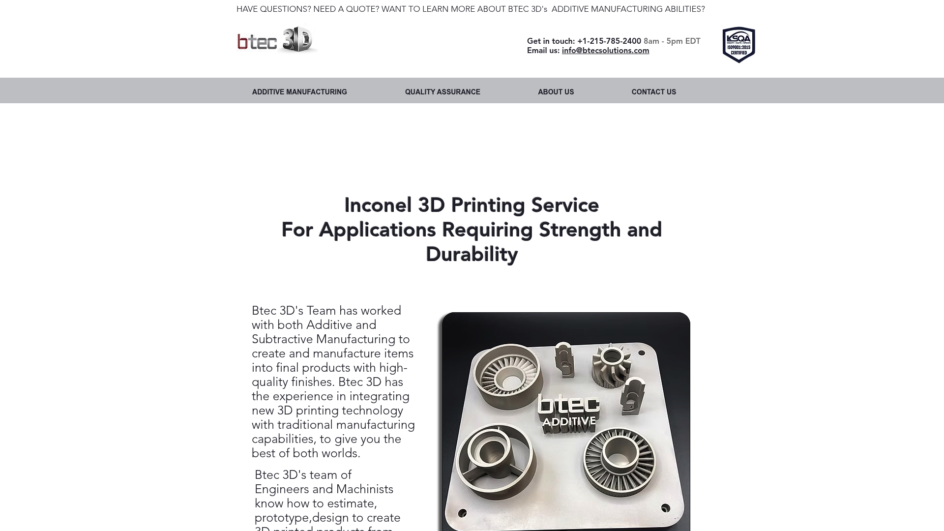
Btec 3D centers its work on Inconel metal 3D printing for parts that need high strength and corrosion resistance. The company pairs additive metal powder processes with traditional machining to produce finished components. Located in Croydon, PA, it targets industrial clients who require durable, precision metal parts.
Core Features
Btec 3D combines additive manufacturing using metal powders with prototyping and custom design services. The team integrates 3D printed metal work into conventional manufacturing workflows and follows quality assurance steps to deliver consistent finishes. The service focus covers end use parts and prototypes requiring strength and mechanical reliability.
Key Differentiator
The standout is a concentration on Inconel metal printing combined with traditional subtractive methods. That mix lets Btec 3D move from raw printed forms to machine finished, fit ready components for industrial applications. This gives an option for projects that need both exotic metal properties and tight tolerances.
Pros
Btec 3D offers a clear strength in producing durable metal parts where material choice matters. Its ability to combine metal powder additive work with machining reduces handoffs and shortens the path to a production ready part. The firm highlights quality assurance and timely delivery, which matters for industrial prototyping and low volume production runs.
Cons
-
No publicly available information on software or platform features. This makes online workflow or automated quoting unclear.
-
Limited detailed product and service specifications online. Buyers must contact the shop for exact machine capabilities and tolerances.
-
No evident integrations with third party software or tools. That limits use where digital order tracking or ERP connectivity is required.
When It May Not Fit
If you need an online portal with automated quoting and file tracking, this provider may not fit. Projects that rely on software integrations for ERP or PLM workflows will find no evidence of those connections. Also, buyers seeking detailed machine specs without phone or email contact will need a different vendor.
Who it’s for
Industrial manufacturers that need high strength metal components and tight mechanical tolerances will get value from Btec 3D. Engineering teams that plan to iterate prototypes into production with a single vendor will benefit from the combined printing and machining approach. It also suits small runs where material performance drives design choices.
Real World Use Case
An aerospace supplier prototyping complex Inconel brackets can use Btec 3D to print near net shape components and then have those machined to final fit. The workflow reduces handling between suppliers and improves accountability for finish and tolerance. That approach shortens the prototype to test cycle for parts that must survive heat and stress.
Pricing
Not applicable. The website presents the company as informational only and does not list public pricing or standard rate cards. Prospective buyers must request a custom quote for any job.
Website: https://btec3d.com
CADTech USA
At a Glance
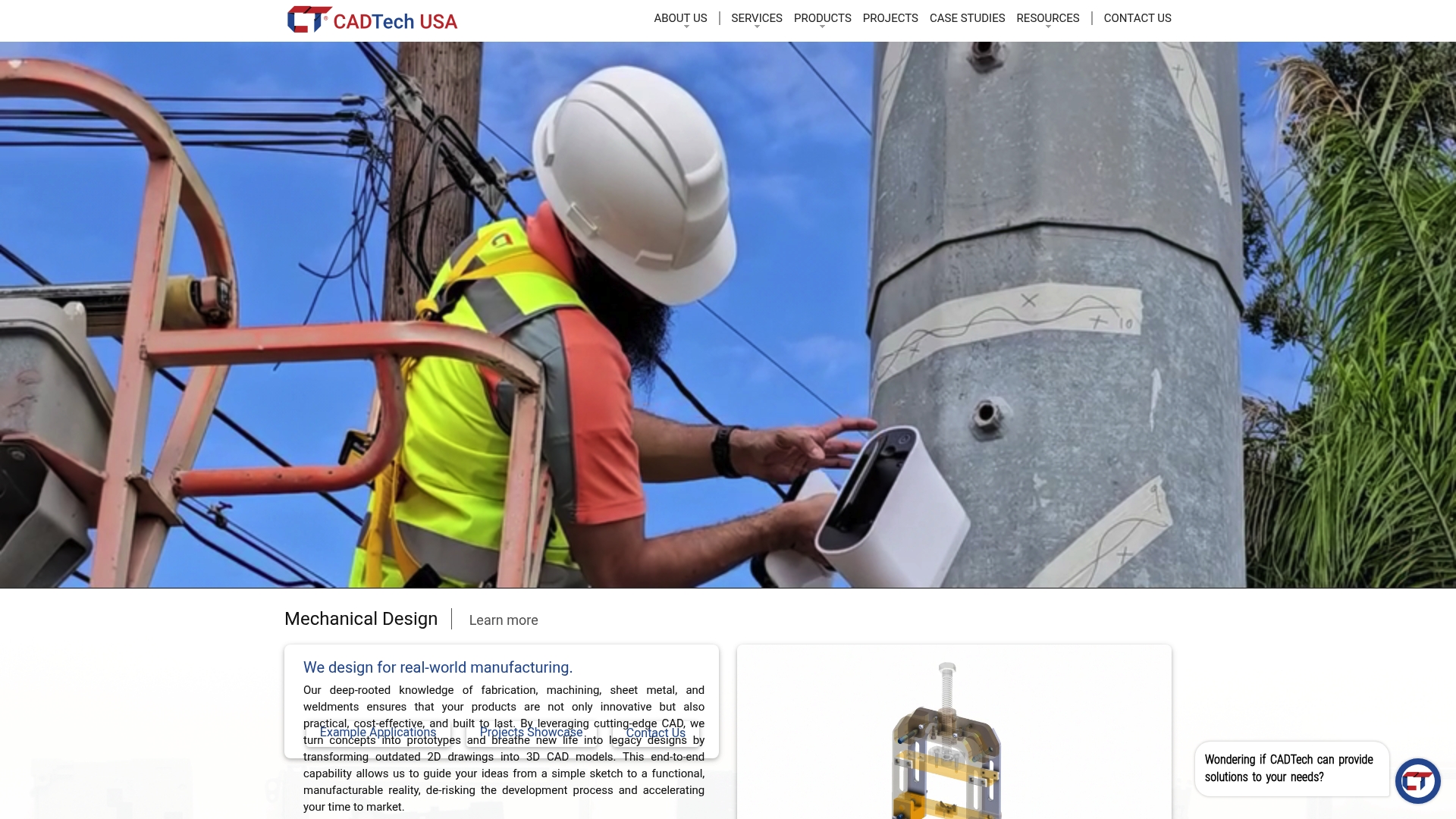
In-house metrology grade scanners capture complex geometries for inspection and reverse engineering. The operation pairs those scanners with Scan to CAD workflows and prototyping to rebuild legacy parts. That focus helps teams move from physical objects to production ready CAD models quickly.
Core Features
CADTech USA combines high resolution 3D scanning with Scan to CAD conversion and mechanical design services. The offering includes prototyping, legacy data conversion, sheet metal and weldment design, and finite element analysis as add on services. The group also supports manufacturing with 3D printing and inspection tied to the digital models.
Key Differentiator
The single standout is the integrated in house chain from digitization to prototype. That means a captured scan becomes an editable CAD file and then a physical prototype without passing work between separate contractors. The vendor claims deep partner relationships that extend the available software and scanner toolset.
Pros
CADTech USA reports over 45 years of combined industry experience. That experience sits alongside professional grade scanners and 3D printers kept in house, which reduces handoffs and shortens lead times. The company lists advanced inspection capability using metrology grade scanners, and it offers additional services like finite element analysis and manufacturing support to close the loop on product development.
Cons
- No third party user reviews are available to confirm usability or long term reliability. Prospective buyers must rely on direct references.
- Public information does not include transparent pricing or published service tiers. You must request a quote for project estimates.
- Limited independent feedback makes it hard to evaluate customer service responsiveness across multiple projects.
When It May Not Fit
If you need publicly available customer ratings before you buy, this will feel risky. The lack of published pricing also makes early budget planning difficult. Large programs that require certified vendor panels or long reference histories should ask for direct project references before committing.
Who It’s For
Manufacturing, engineering, and design firms that need precise digital twin creation and reverse engineering will find the offering relevant. Product developers who must convert legacy drawings or obsolete parts into modern CAD models should consider this provider. The service targets projects that benefit from a single vendor handling scan, CAD, and prototyping.
Real World Use Case
A manufacturer used CADTech USA’s Scan to CAD service to recreate obsolete equipment parts from legacy drawings. The result produced modern 3D models that supported cost effective production runs and design upgrades. The project eliminated repeated trial fits and sped the replacement part release.
Pricing
Pricing is not published on the website. CADTech USA lists services as informational only and asks prospective clients to request a project quote. Contact the team with part details for an estimate and lead time.
Website: https://cadtechusa.com
Comparison of alternatives
Choosing an appropriate 3D printing provider is vital when considering project requirements such as exact specifications, material compatibility, and in-house capabilities. Below, we assess some top contenders, focusing on their unique offerings and specializations to provide you a clear picture.
Material offering and printing quality
CC 3D Labs stands out in producing multi-material, multi-color 3D printed parts. Its integration of metrology-grade scanning combined with in-house tool calibration allows for exceptional precision, ensuring the resulting prints are dimensionally accurate. Btec 3D, on the other hand, takes a specialized debris path by focusing on Inconel metal 3D printing, delivering high-strength and corrosion-resistant components vital for industries like aerospace and high-performance engineering. For intricate part duplication, CADTech USA excels in producing accurate digital renderings for later prototyping or mass manufacturing.
Additional services and customer profiles
Organizations with prototyping and product development needs may benefit more from CADTech USA, given its range of supplementary services including Scan to CAD, reverse engineering, and finite element analysis. CC 3D Labs, however, offers local support, fast turnaround, and precise prototyping, targeting smaller businesses and individual creators. Meanwhile, Btec 3D tailors its services to industrial manufacturing, where the production of durable, complex components takes precedence.
Best fit
- Complex projects requiring precise, multi-material, and multi-color 3D printing alongside expedited turnaround can maximize resources with CC 3D Labs.
- Manufacturing processes dependent on integrating Inconel 3D printing with traditional machining benefit significantly from Btec 3D.
- Engineering projects requiring high-quality digital model creation and organic legacy reinstatements find an aligned partner in CADTech USA.
Our pick
For clients primarily focused on achieving dimensional accuracy in prototypes paired with flexible material options, CC 3D Labs excels by providing metrology-grade scanning and precise manufacturing capabilities. However, those with highly specific material needs or complex metallic requirements might find Btec 3D a more suitable choice.
Multiple options provide custom 3D printing services, aiding prototype development and production readiness with unique methods and material advantages.
| Product Name | Core Feature | Key Differentiator | Best For | Pricing | Notable Limitation |
|---|---|---|---|---|---|
| Cc3dlabs | Multicolor, multimaterial 3D printing | Metrology-grade scanning accuracy | Product developers | Price not published | Higher costs for large-volume projects |
| Btec 3D | Metal powder additive manufacturing | Inconel metal printing technique | Industrial manufacturers | Price not published | Limited online service information |
| CADTech USA | Scan to CAD workflows and prototyping | Integrated digital to physical production | Manufacturing and design firms | Price not published | Lack of accessible user reviews |
What Challenges Do Tangiblecreative.com Alternatives Address for Product Developers?
Finding a 3D printing partner who offers precise, multi-material, and multi-color solutions with guaranteed dimensional accuracy is often a top concern. Product developers and small to medium businesses need reliable services that combine design support, metrology-grade scanning, and fast turnaround to reduce iteration cycles and avoid wasted materials.
Cc3dlabs provides a solid alternative with its local pickup options, free online estimates, and comprehensive filament choices. Their in-house calibration and 3D scanning ensure your prototypes and small batch production parts meet exact specifications. Explore how Cc3dlabs can support your projects at Cc3dlabs and get started with design assistance and precise prototyping today.
Learn more about their services and see how their quality and speed help you meet your product goals with confidence.
FAQ
What features make Cc3dlabs a good option for custom 3D printing services?
Cc3dlabs provides metrology grade 3D scanning and in-house tool calibration, ensuring high dimensional accuracy for finished parts. These capabilities support the production of prototypes and functional parts in multiple colors and materials. Readers looking for precise 3D printing solutions should consider Cc3dlabs for their next project.
How does Btec 3D compare to Cc3dlabs for metal 3D printing needs?
Btec 3D specializes in Inconel metal 3D printing, delivering parts with high strength and corrosion resistance. Cc3dlabs excels in custom 3D printing for a variety of prototyping needs, making it a better choice if your project requires diverse material options and metrology grade scanning.
What is the turnaround time for services at Cc3dlabs?
Cc3dlabs offers fast turnaround for local clients, which can significantly reduce iteration time for nearby projects. This efficiency allows product developers to quickly test and iterate their designs before moving to production, enhancing the overall development cycle.
Can I expect design support when using Cc3dlabs for my 3D printing projects?
Cc3dlabs provides design support alongside their printing services, helping customers navigate the transition from CAD to finished parts. This assistance streamlines the development process, making it easier for clients to achieve their desired results.
How does the pricing at Cc3dlabs compare to other services?
Pricing at Cc3dlabs varies based on project complexity, material, and quantity, with the vendor offering free online estimates. This allows potential clients to assess costs before committing, making it a convenient option in the competitive landscape of custom 3D printing.