TL;DR:
- Prototypes are essential for reducing product development risks by enabling early flaw detection at lower costs. Iterative testing with the right fidelity accelerates learning, improves design quality, and facilitates stakeholder agreement. Speedy prototyping, especially through 3D printing and digital tools, can significantly cut time and expenses in bringing products to market.
A prototype is a preliminary, low-cost model built to test a product idea before full-scale development, and it is the single most effective tool for reducing risk in any product pipeline. The core argument for why prototypes matter is simple: fixing a design flaw during prototyping costs a fraction of what it costs after launch. Companies that integrate rapid prototyping cut development time by 50% and reduce production costs by roughly one-third. That is not a marginal gain. That is the difference between a product that ships on budget and one that bleeds cash through endless post-launch patches.
Why do prototypes matter for reducing time and cost?
Teams that skip prototyping spend 3–5 times more on redesign after development, because fixing usability issues post-launch costs 10–100 times more than catching them early. That multiplier is the clearest financial argument for building before you build at scale. Every hour spent on a rough prototype is buying information that would otherwise cost ten hours of engineering rework.

Rapid prototyping techniques, including filament-based 3D printing, paper mockups, and digital wireframes, compress iteration cycles from weeks to days. Shorter cycles mean more tests per dollar spent. The role of prototypes in design is not just aesthetic validation. It is a systematic way to surface structural, functional, and usability problems before they become expensive commitments.
| Scenario | Typical cost impact | Time to fix |
|---|---|---|
| Fix caught during prototyping | Low | Hours to days |
| Fix caught during development | Moderate | Days to weeks |
| Fix caught post-launch | Very high (10–100x more) | Weeks to months |
| Skipping prototyping entirely | 3–5x redesign cost increase | Unpredictable |
Pro Tip: Build your first prototype with the explicit goal of breaking it. The faster you find what fails, the less you spend fixing it later.
What are the main types of prototypes used in development?
Prototype fidelity describes how closely a model resembles the final product, and selecting the right fidelity depends entirely on what you are trying to learn. Low-fidelity prototypes are fast and cheap. High-fidelity prototypes are detailed and testable. Using the wrong type at the wrong stage wastes both.
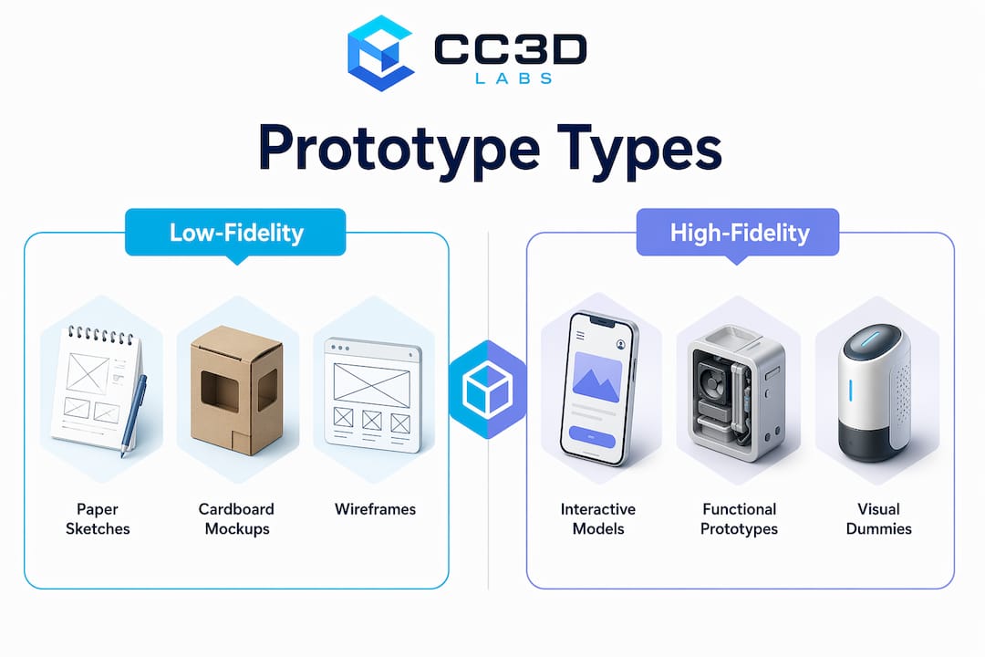
Low-fidelity prototypes
Low-fidelity models include paper sketches, cardboard mockups, and basic digital wireframes. They are built for concept validation, not visual polish. The goal is to test whether the core idea holds up before investing in detail.
High-fidelity prototypes
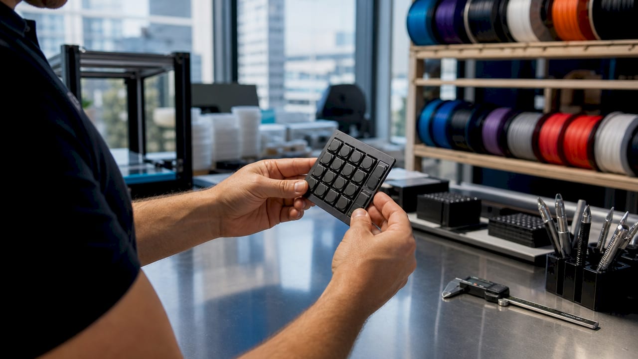
High-fidelity prototypes are built for usability testing, stakeholder approval, and developer handoffs. They replicate the look, feel, and interaction of the final product closely enough to generate reliable user feedback. A high-fidelity physical prototype produced via 3D printing, for example, lets testers grip, assemble, and stress-test a part under real conditions.
| Fidelity level | Best use case | Typical format |
|---|---|---|
| Low-fidelity | Concept validation, early brainstorming | Paper sketches, foam models |
| Mid-fidelity | Flow testing, layout review | Digital wireframes, basic CAD |
| High-fidelity | Usability testing, stakeholder sign-off | Interactive mockups, 3D prints |
| Functional prototype | Engineering validation, stress testing | Printed or machined parts |
The best practice is to start low and move high only when the concept is stable. Jumping straight to a high-fidelity model before validating the core idea is one of the most common and expensive mistakes in product development.
- Match fidelity to your learning goal, not your timeline pressure.
- Use low-fidelity models to kill bad ideas cheaply.
- Reserve high-fidelity builds for questions that require realistic interaction.
- Document what each prototype is designed to test before you build it.
Why does prototype iteration matter for better products?
Rapid prototyping prioritizes speed over polish, enabling teams to fail fast and learn fast. That phrase is not a startup cliché. It is a description of how information compounds. Each iteration answers a specific question, and the answer shapes the next version. Teams that iterate five times before launch arrive at a fundamentally better product than teams that iterate once.
Structuring tests around measurable hypotheses improves feedback quality and stakeholder confidence. Vague questions produce vague answers. Asking “Can users complete checkout in under 90 seconds?” generates data. Asking “What do you think of the design?” generates opinions.
Effective prototype testing requires setting clear expectations with users before the session begins. Without that framing, testers fixate on missing images or visual glitches instead of evaluating the core functionality. That misdirected feedback wastes a test session and can send a team in the wrong direction.
Pro Tip: Before each test session, tell participants: “This is an early model. We are testing the concept, not the visuals. Please ignore anything that looks unfinished.”
The best iteration cycles follow a tight loop: build a focused prototype, test one hypothesis, record the result, and update the design. Repeating that loop six times produces more learning than one elaborate test at the end of a development sprint.
- Define one primary hypothesis per prototype.
- Set a task completion metric before testing begins.
- Debrief the team within 24 hours of each session.
- Update the prototype based on findings before the next round.
- Track which assumptions have been validated and which remain open.
What practical steps help teams implement prototyping effectively?
The first step is identifying your riskiest assumption. Every product concept rests on a stack of assumptions, and not all of them carry equal risk. The assumption most likely to kill the product if wrong is the one to test first. Building a prototype around a low-risk assumption wastes a cycle.
Once the target assumption is clear, choose the fastest format that can test it. For digital products, tools like Figma allow interactive prototypes in hours. For physical products, rapid prototyping via 3D printing produces testable parts in days rather than weeks. The format should match the question, not the team’s preferred workflow.
Collaboration is the second major lever. Interactive prototypes replace lengthy written specs in stakeholder meetings. A product manager who walks into a review with a working model instead of a slide deck controls the conversation. The model makes the product tangible, and tangible things get decisions made faster.
- List every major assumption your product concept depends on.
- Rank them by risk: which one, if wrong, kills the product?
- Build the simplest prototype that tests the top-ranked assumption.
- Run a structured test with at least three users or reviewers.
- Record results against your hypothesis, not against general impressions.
- Update the design and repeat for the next assumption on the list.
- Escalate fidelity only after the core concept survives low-fidelity testing.
Balancing speed and detail is a judgment call that improves with practice. The guiding principle is that a prototype should be just detailed enough to answer the question it was built to answer. Anything beyond that is waste. Teams that internalize this principle ship faster and spend less. Manufacturers looking to stay ahead can also benefit from digital marketing trends that align product validation with go-to-market timing.
How do working prototypes improve stakeholder communication?
Working prototypes provide more influence and credibility than static specs among product teams and stakeholders. A written requirement document describes a product. A prototype demonstrates one. That difference in mode changes how people respond.
Abstract debates about features, layouts, and user flows collapse when a prototype enters the room. Stakeholders stop arguing about what something might feel like and start reacting to what it actually does. That shift from speculation to reaction accelerates decisions and reduces the risk of building the wrong thing based on executive assumptions.
“Prototypes short-circuit abstract debates and make project viability tangible. When stakeholders can interact with a model, they stop debating what the product should do and start evaluating whether it works.”
Top product managers use prototyping as a career-advancing tool to gain data, influence, and credibility faster than writing documentation. Shipping multiple prototypes builds professional momentum that formal product requirement documents simply cannot match. The prototype is the argument.
Key Takeaways
Prototypes are the most cost-effective tool in product development because they convert untested assumptions into validated decisions before full-scale production begins.
| Point | Details |
|---|---|
| Early fixes cost far less | Post-launch fixes cost 10–100 times more than changes made during prototyping. |
| Match fidelity to the goal | Use low-fidelity models for concept validation and high-fidelity builds for usability testing. |
| Iterate with a hypothesis | Define one measurable question per prototype to generate useful, specific feedback. |
| Prototypes beat written specs | Working models accelerate stakeholder decisions by making the product tangible, not abstract. |
| Speed beats polish early on | Rapid iteration cycles produce more learning per dollar than one polished prototype at the end. |
The uncomfortable truth about prototyping most teams ignore
Most teams treat prototyping as a phase. They schedule it, complete it, and move on. That framing misses the point entirely.
Prototyping is a mindset. The question “how can I test this assumption cheaply before committing?” should run through every stage of development, not just the weeks labeled “prototyping” on a Gantt chart. I have watched product teams spend three months building a feature that a two-day paper prototype would have killed in week one. The cost was not just money. It was morale, momentum, and market timing.
The other mistake I see constantly is over-investing in fidelity too early. Teams build beautiful, detailed models before they have validated the core concept. They fall in love with the prototype and lose the objectivity needed to kill it when the data says to. James Dyson’s discipline is instructive here. He treated each of his failed prototypes as a targeted inquiry, buying information at a fraction of the cost of a failed launch. That framing removes the emotional sting of scrapping a version and replaces it with a clear-eyed view of what was learned.
The career impact is real too. Product managers who prototype frequently build a track record of data-driven decisions. That is a different professional identity than the manager who writes detailed specs and waits for engineering to validate them. One of those people controls the room. The other hopes the room agrees with their document.
Start ugly. Test early. Iterate fast. The polish comes later, and it lands on a foundation that has already been stress-tested.
— Justin
Cc3dlabs turns your prototype concepts into physical reality
Product developers who need physical prototypes fast have a direct path at Cc3dlabs, a professional 3D printing and scanning service near Philadelphia. Whether you need a single functional part to stress-test an assumption or a batch of models for a stakeholder review, Cc3dlabs produces high-quality 3D printed prototypes with tight tolerances and quick turnaround times.

Cc3dlabs also offers metrology-grade 3D scanning for design accuracy, which feeds precise measurements directly back into your CAD workflow. That closed loop between physical testing and digital refinement is exactly what rapid iteration demands. Request a free online estimate and move your next prototype from concept to testable model faster than your current process allows.
FAQ
What is the main benefit of prototyping in product development?
Prototyping catches design flaws and usability problems before full-scale production begins. Teams that prototype reduce development time by 50% and cut production costs by roughly one-third.
When should you use a low-fidelity vs. a high-fidelity prototype?
Use low-fidelity prototypes for early concept validation when speed matters most. Switch to high-fidelity prototypes when you need reliable usability data or stakeholder sign-off.
Why does prototype iteration matter more than a single test?
Each iteration answers one specific question and shapes the next version. Teams that run multiple short cycles arrive at better products than those that test once at the end of development.
How do prototypes help with stakeholder buy-in?
Working prototypes make a product tangible, which shifts stakeholder conversations from abstract debate to direct evaluation. That shift speeds up decisions and reduces the risk of building the wrong feature.
Can 3D printing be used for rapid prototyping?
Yes. Filament-based 3D printing produces testable physical parts in days, making it one of the fastest methods for functional prototype development in hardware and product design.