
TL;DR:
- Additive manufacturing allows rapid creation of functional robot components directly from digital files. It enables customization of geometry and material, making prototyping faster and more accessible for small teams and individual developers. Proper design, material choice, and calibration are essential for producing durable, reliable robotic parts.
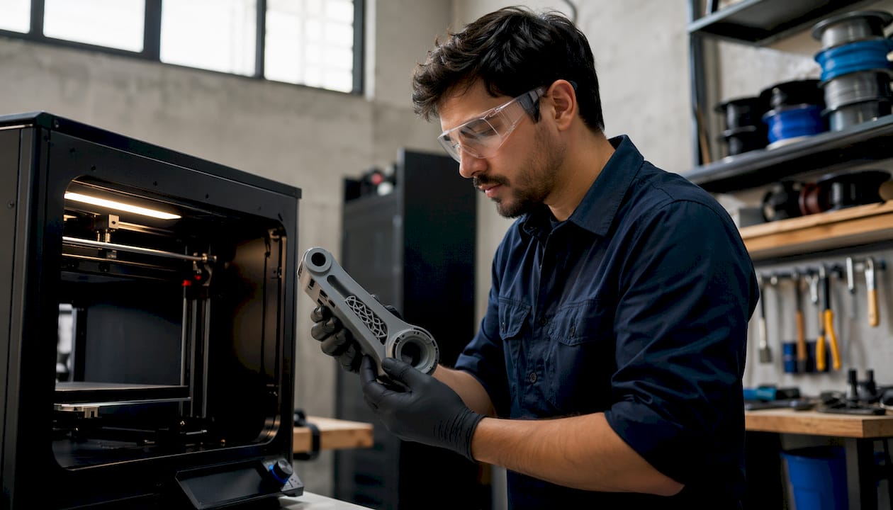
Additive manufacturing for robotics is defined as the process of producing functional mechanical components layer by layer from digital files, and it is the fastest way to go from concept to working prototype. Building custom robot parts with 3D printing gives engineers direct control over geometry, material, and iteration speed that traditional machining cannot match. A fully functional robotic arm can be built for around $220 in materials using standard servos and a desktop FDM printer. That cost point makes serious robotics prototyping accessible to individual developers and small teams for the first time.
What do you need to start building custom robot parts with 3D printing?
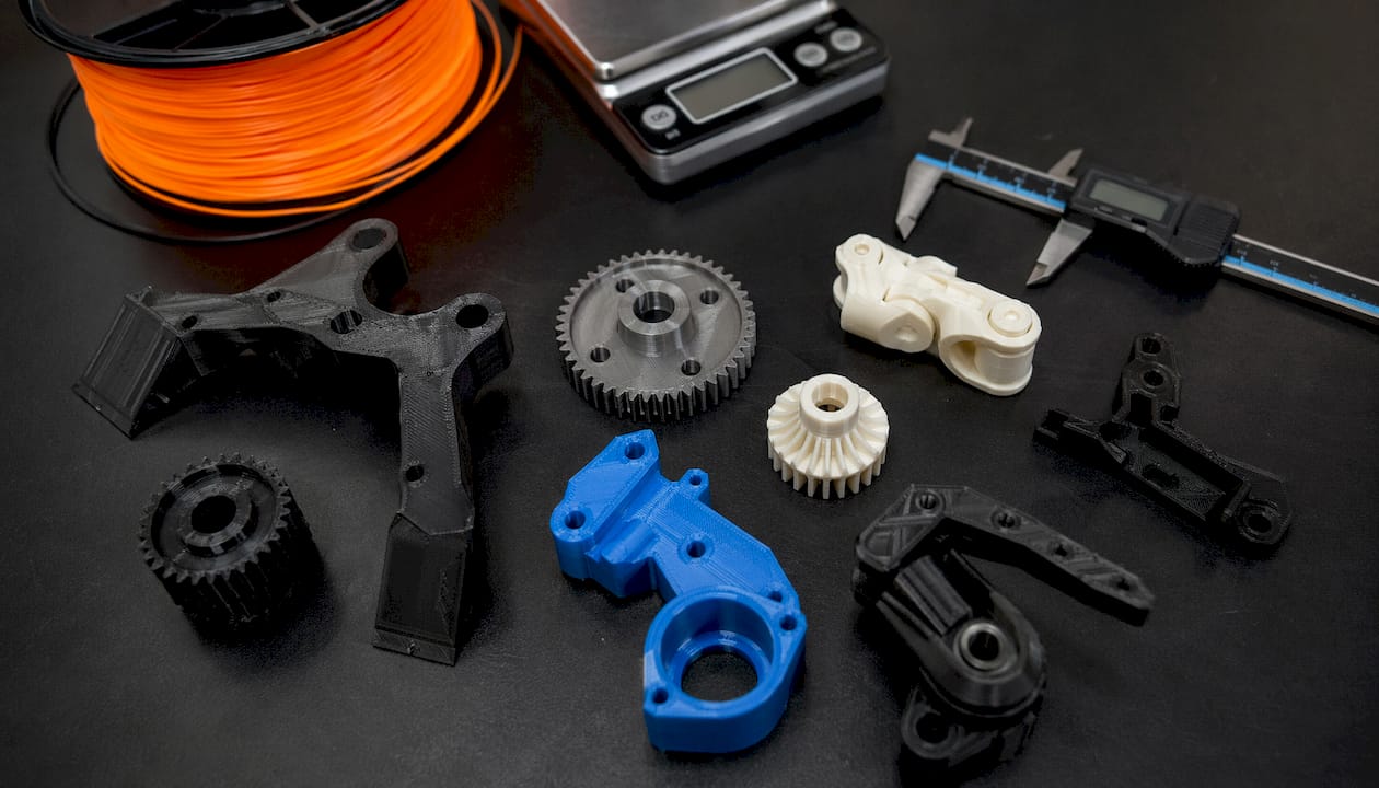
The right equipment determines whether your printed parts are functional or frustrating. Three printer technologies cover most robotics applications: FDM, SLA, and SLS. Each has a distinct role.
FDM printing offers fast, low-cost prototyping with visible layer lines and anisotropic strength. That means the part is stronger along the X and Y axes than along the Z axis. SLA produces high-resolution parts with smooth surfaces, which is useful for small linkages and sensor housings. SLS delivers isotropic strength and complex geometry without support structures, but at a significantly higher cost per part. For most product developers starting out, FDM is the correct first choice.
Choosing the right filament
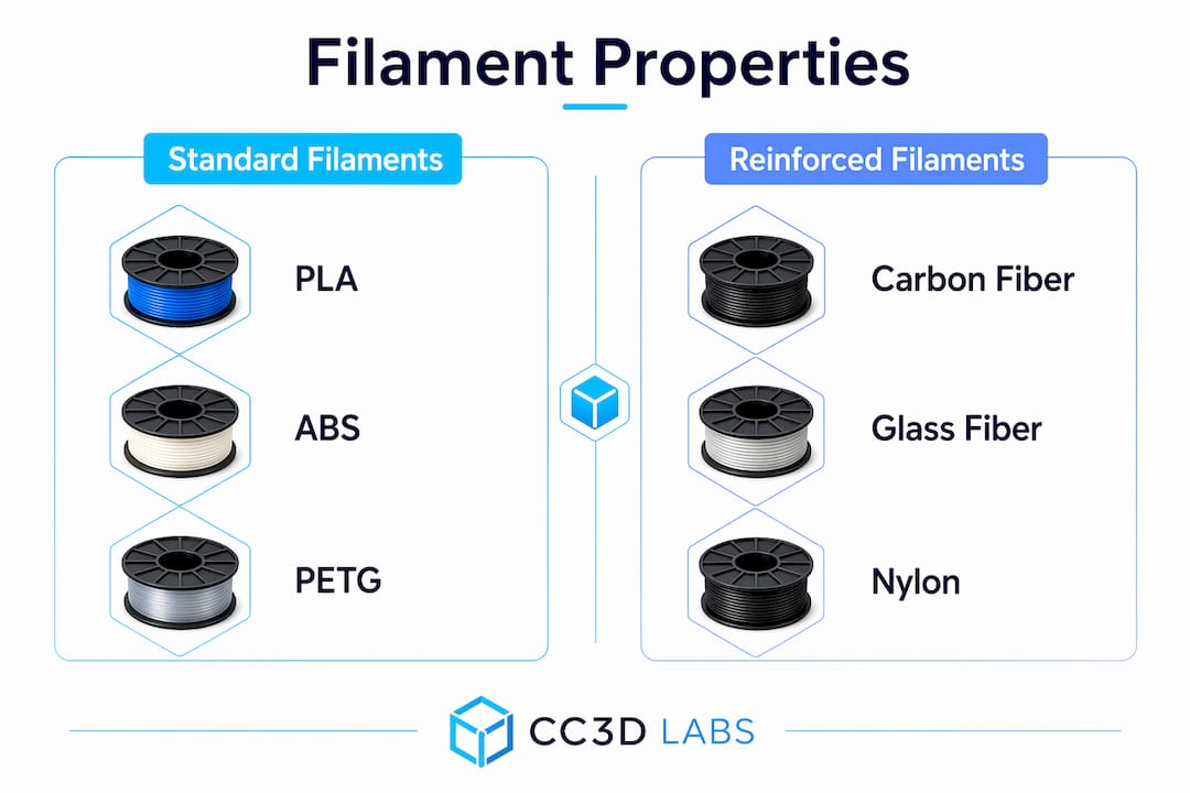
Material selection is the single biggest variable in part performance. The table below summarizes the four filaments engineers use most often for 3D printed robot components.
| Filament | Strength | Heat resistance | Best use |
|---|---|---|---|
| PLA | Moderate | Low (~60°C) | Prototypes, non-load-bearing frames |
| PETG | Good | Medium (~80°C) | Structural brackets, enclosures |
| ABS | Good | High (~100°C) | Housings, gears, functional parts |
| Carbon fiber reinforced | High | High | Load-bearing arms, structural links |
Carbon and glass fiber reinforced filaments provide higher stiffness and heat resistance but require careful print parameter tuning to avoid delamination. For a deeper breakdown of how these materials compare in real applications, the PLA vs. PETG vs. ABS guide from Cc3dlabs covers the tradeoffs in detail.
Software and hardware essentials
CAD software such as Fusion 360, SolidWorks, or FreeCAD handles part geometry. A slicer like PrusaSlicer or Bambu Studio converts the model into printer instructions. Beyond the printer, you need servo motors, M3/M4 fasteners, heat-set brass inserts, and a soldering iron for electronics integration.
How do you design robot parts for strength and function?
Good robot parts design starts with two principles: modularity and load path awareness. Both directly affect how long your parts last and how fast you can fix them when they fail.
Modular robot design with replaceable sub-assemblies improves maintenance speed and iteration rate compared to monolithic designs. When a joint bracket breaks, you reprint that one piece instead of rebuilding the entire arm. This approach also lets you test different geometries for a single joint without redesigning the whole robot.
Print orientation and infill
Selecting infill patterns, wall perimeters of 3 or more, and correct print orientation is critical for structural integrity in functional printed parts. Novice designers consistently underestimate anisotropic stresses, which causes premature part failure under load. Orient parts so the primary load runs parallel to the print layers, not perpendicular to them. For infill, gyroid and honeycomb patterns distribute stress more evenly than rectilinear in parts that experience multi-directional loading. The 3D print infill guide from Cc3dlabs explains pattern selection with specific strength data.
Tolerances and calibration
Dimensional accuracy determines whether your assembly fits together or binds. Print a calibration cube before committing to a full part run. Measure the result with calipers and apply a scaling correction in your slicer or CAD file. For press-fit joints, start with 0.1–0.2mm clearance and adjust based on your printer’s actual output. Calibration prints and measured offsets in CAD or the slicer correct dimensional inaccuracies before they become assembly problems.
Pro Tip: Design cable routing channels and mounting bosses directly into your printed parts. Integrated wiring channels reduce clutter, protect wires from mechanical wear, and make the assembly far easier to service.
What is the step-by-step process for printing and assembling robot parts?
Execution follows a clear sequence. Skipping steps, especially in post-processing, is the most common reason functional parts fail in the field.
- Prepare your CAD file. Export as STL or 3MF. Check for non-manifold geometry using Meshmixer or your slicer’s repair tool.
- Set slicing parameters. Use 3+ wall perimeters, 30–40% infill for structural parts, and orient the part for maximum load-path alignment.
- Print structural components. Enable supports only where geometry requires them. Unnecessary supports add removal time and can damage surface finish.
- Remove supports and post-process. Clean support interfaces with flush cutters and needle-nose pliers. For PETG and ABS, annealing and surface treatment relieve internal stresses and improve fatigue resistance.
- Install heat-set inserts. Use a soldering iron set to the filament’s softening temperature. Press inserts in straight to avoid angled threads.
- Mount servos and electronics. Secure servos with M3 screws into the heat-set inserts. Route wiring through the printed channels before closing any covers.
- Test under load before final assembly. Run the joint through its full range of motion with the servo powered. Listen for binding and check for flex in the bracket.
The table below summarizes each phase with realistic time estimates for a single robotic arm joint.
| Phase | Key action | Estimated time |
|---|---|---|
| File prep | CAD export, repair, slicer setup | 30–60 minutes |
| Printing | Structural parts at standard quality | 2–6 hours |
| Post-processing | Support removal, annealing, sanding | 30–90 minutes |
| Hardware integration | Inserts, servos, wiring | 45–90 minutes |
| Testing | Load test, fit check, iteration | 30–60 minutes |
Pro Tip: Print a single test joint before committing to a full arm print. A 20-minute test part catches fit and clearance problems that would otherwise waste hours of print time.
How do you troubleshoot common issues with 3D-printed robot parts?
Most print and assembly failures have a known cause and a direct fix. The key is diagnosing the right layer of the problem.
- Warping: Caused by thermal contraction during cooling. Fix with a heated bed, enclosure, or brim. ABS requires an enclosure; PETG rarely warps on a heated glass bed.
- Under-extrusion: Produces weak, porous layers. Check for a partial clog, reduce print speed by 20%, and verify your extruder steps-per-millimeter calibration.
- Layer delamination: Usually caused by printing too fast or at too low a temperature. Increase nozzle temperature by 5°C increments until layers bond properly.
- Dimensional inaccuracy: Parts that are consistently oversized or undersized need a flow rate or XY scaling correction in the slicer. Measure a calibration cube and apply the offset.
- Stripped heat-set inserts: Caused by under-sized holes or inserts installed at an angle. Redesign the boss with a 0.1mm larger bore and reinstall with a straight press.
- Joint flex or failure: Increase wall count to 4–5 perimeters, switch to a stiffer filament, or reorient the part so the load runs along the print layers.
For modular designs, the repair strategy is straightforward. Identify the failed sub-assembly, reprint only that component, and swap it in. This is the core advantage of modular design for maintenance. Keeping a small stock of commonly stressed parts, such as wrist brackets and servo mounts, eliminates downtime during testing cycles.
One often-overlooked failure mode is fatigue from vibration. Parts that pass a static load test can still crack after repeated motion cycles. Test every joint through at least 500 full cycles before declaring a design production-ready. If you are working with high-speed or high-load applications, carbon fiber part failure modes are worth understanding before you commit to reinforced filaments.
Key Takeaways
Building custom robot parts with 3D printing requires material selection, design optimization for anisotropic strength, and a modular assembly approach to produce reliable, maintainable robotic components.
| Point | Details |
|---|---|
| Material choice drives performance | Match filament to load and heat requirements; use PETG or ABS for structural parts. |
| Print orientation is structural | Orient parts so primary loads run parallel to print layers to avoid anisotropic failure. |
| Modular design speeds iteration | Build robots as collections of replaceable sub-assemblies to cut repair and testing time. |
| Post-processing matters | Annealing and surface treatment improve fatigue resistance and dimensional accuracy. |
| Calibrate before full production | Run calibration prints and apply measured offsets before printing final functional parts. |
What I’ve learned from printing robot parts that textbooks skip
The biggest mistake I see engineers make is treating 3D printing as a direct substitute for machined metal. It is not. It is a different manufacturing method with its own failure modes, and the ones that catch people off guard are almost always orientation-related. A bracket that looks overbuilt on screen can split cleanly along a layer line under a load that machined aluminum would shrug off. The fix is not always more material. Often it is just a 90-degree rotation in the slicer.
The second lesson is that modular design is not just a maintenance convenience. It is a prototyping accelerator. When you build a robot as a collection of discrete, replaceable joints and brackets, you can run parallel experiments. Print three versions of a wrist joint with different wall counts, test them simultaneously, and have a winner in a day. Monolithic designs force you to reprint the whole assembly every time you change one variable.
My honest recommendation for anyone starting out: spend more time on your first calibration print than you think you need to. Measure every face of the calibration cube, apply the corrections, and print it again. The 45 minutes you invest there will save you hours of failed assemblies later. The functional parts printing guide from Cc3dlabs covers this calibration workflow in depth and is worth reading before your first structural print.
— Justin
Cc3dlabs can print your custom robot parts with precision
Cc3dlabs is a professional 3D printing service based near Philadelphia, specializing in filament-based printing for functional parts, prototypes, and batch production. Engineers and product developers use Cc3dlabs when they need parts that meet tight tolerances without the overhead of running their own print farm.

The team at Cc3dlabs handles everything from CAD modeling and design support to multi-color printing and post-processing. Turnaround times are fast, and the service scales from a single prototype to production-volume orders. Whether you need a one-off joint bracket or a full set of custom robotic components, Cc3dlabs delivers parts ready for assembly. Request a free online estimate directly on the website and get a quote without a sales call.
FAQ
What is the cheapest way to build a 3D-printed robot arm?
A fully 3D-printed robotic arm costs approximately $220 in materials using standard servos and a desktop FDM printer, excluding the printer itself. PLA or PETG filament keeps per-part costs low while still delivering adequate strength for light-duty applications.
Which filament is best for structural robot parts?
PETG is the best starting point for structural 3D printed robot components because it balances strength, heat resistance, and printability. Carbon fiber reinforced filaments offer higher stiffness for demanding applications but require careful print settings to avoid delamination.
How do I make 3D-printed robot parts stronger?
Use 3 or more wall perimeters, orient parts so the primary load runs parallel to the print layers, and choose an infill pattern like gyroid or honeycomb for multi-directional stress. Post-processing with annealing further improves fatigue resistance.
What CAD software works best for robot parts design?
Fusion 360 and SolidWorks are the most widely used CAD tools for custom 3D parts for robotics because both support parametric modeling and direct STL export. FreeCAD is a capable free alternative for engineers on a tight budget.
How tight should tolerances be for 3D-printed robot joints?
Start with 0.1–0.2mm clearance for moving joints and adjust based on calibration prints measured with calipers. Applying a scaling correction in your slicer before printing final parts prevents fit problems during assembly.