
TL;DR:
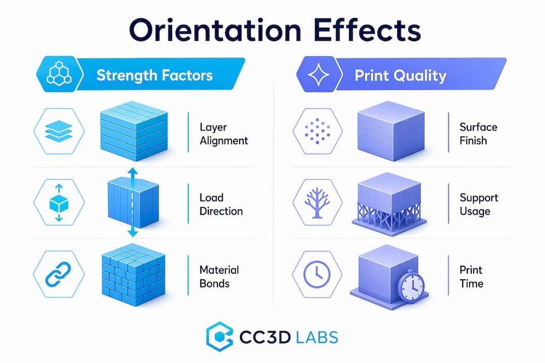
- Print orientation in 3D printing determines a model’s position on the build plate, affecting strength, finish, support needs, and print time. Properly aligning layers with the primary load direction enhances part durability, while surface quality depends on how flat surfaces are oriented relative to the build plate. Using the correct orientation minimizes supports and reduces overall production costs and duration.
Print orientation is defined as the position and direction a 3D model occupies on the build plate before and during printing. That single decision shapes the part’s mechanical strength, surface finish, support material needs, and total print time. Hobbyists and product developers alike often treat orientation as an afterthought. Professionals at shops like Cc3dlabs treat it as the first design decision. This guide breaks down every major effect of print orientation so you can make smarter choices before your next print starts.
What is print orientation and why does it matter in 3D printing?
Print orientation, known in manufacturing as build orientation, is the angle and axis at which a model is placed relative to the build plate in a 3D printer. In FDM (Fused Deposition Modeling) printing, the printer deposits material layer by layer from the bottom up. The direction those layers stack determines almost everything about the final part.
Think of it like wood grain. A plank of wood is strong along the grain and splits easily across it. FDM printed parts behave the same way. FDM parts are anisotropic, meaning their strength varies depending on the direction of the applied force relative to the layer lines. That single fact is the foundation of every orientation decision you will make.
Orientation also controls how tall a print is, which directly affects how many layers the printer must deposit. More layers mean more time. The wrong orientation can also force the slicer to generate support structures for overhangs, adding material waste and post-processing work. Getting orientation right before you hit print is the highest-leverage decision in the entire workflow.
How does print orientation affect the strength of a 3D printed part?
The bond between two adjacent layers in an FDM print is always weaker than the continuous filament running within a single layer. Stress applied perpendicular to layer interfaces causes delamination and reduced tensile strength. That is the core mechanical risk of poor orientation.
The fix is straightforward: align the primary load direction with the layer lines, not across them. If a bracket will be pulled along its length, print it so the layers run lengthwise. If a clip will flex open and closed, orient it so the bending stress runs parallel to the layers, not perpendicular to them. This is how you validate 3D designs for real-world loads before committing to a production run.
SLA and SLS technologies are less sensitive to this issue. SLA parts cure in a resin pool and have more isotropic properties. SLS parts are sintered in powder and show minimal directional weakness. But for FDM, which covers the vast majority of desktop and professional filament printers, orientation is a structural decision, not just a visual one.
Pro Tip: Orient load-bearing surfaces parallel to the build plate. That keeps the strongest filament continuity aligned with the direction of stress and dramatically reduces the risk of layer separation under load.
What impact does print orientation have on surface finish and aesthetics?
Surface finish is where orientation choices become visible to anyone who picks up the part. Flat surfaces printed parallel to the build plate produce the smoothest result because the layers stack cleanly on top of each other with minimal visible stepping.
Angled or vertical faces tell a different story. When a curved or diagonal surface rises along the Z-axis, each layer creates a small horizontal step. This is called the stair-stepping effect, and it becomes more pronounced as the surface angle becomes shallower relative to the build plate. A 15-degree slope will show far more stepping than a 60-degree slope.
Here are the key rules for orientation when appearance matters:
- Cosmetic faces go down or sideways. Place the most visible surface against the build plate or parallel to it for the smoothest result.
- Avoid the Z-axis for precision fits. Critical mating surfaces oriented along the Z-axis lose dimensional accuracy due to stair-stepping, which can ruin a snap-fit or press-fit joint.
- Curved features need careful planning. Cylinders printed vertically show stepping around their circumference. Printing them horizontally produces a smoother outer wall but weakens the part along its length.
- Prioritize the surface the end user will see. If only one face of a part is visible in its final assembly, orient that face for the best finish, even if it means a slightly weaker structure elsewhere.
The trade-off between strength and surface finish is the most common tension in orientation decisions. There is rarely a single orientation that maximizes both. The key is knowing which property matters more for your specific part.
How does print orientation influence support material usage and print efficiency?
Supports are structures the slicer generates automatically to hold up any portion of the model that overhangs more than roughly 45 degrees from vertical. Overhangs greater than 45 degrees require support material, which increases filament consumption and adds post-processing time for removal and sanding. Optimizing orientation to minimize supports can reduce filament consumption by 20–50%. That is a significant cost and time saving on any print, and it compounds across batch production runs.
Print time is the second efficiency factor. Taller parts require more layers, and each additional layer adds time. A part printed upright at 120mm tall will take considerably longer than the same part printed flat at 30mm tall. Reducing vertical height by rotating the model is one of the fastest ways to cut print duration without changing any slicer settings.
The table below shows how the three main orientation strategies compare across the key efficiency metrics:
| Orientation | Support volume | Print time | Surface quality | Strength direction |
|---|---|---|---|---|
| Flat (horizontal) | Low | Fast | High on top face | Strong along XY plane |
| Upright (vertical) | Medium | Slow | Moderate on sides | Strong along Z-axis |
| Angled (tilted) | High | Medium | Variable | Distributed across axes |
Pro Tip: Decide on orientation during the design phase, not after the model is finished. Small geometry changes, like adding a flat face or chamfering an overhang, can eliminate entire support structures and save hours of print time and post-processing.
You can find more detail on reducing waste and labor through smart orientation in this guide to cutting 3D printing costs.
What are the main print orientation types in 3D printing?
The three primary orientation types in 3D printing are flat, upright, and angled. Each produces a different balance of strength, finish, and efficiency.
Flat orientation places the model with its largest face on the build plate. This minimizes print height, reduces supports, and produces the best surface finish on the top face. It is the default choice for wide, thin parts like brackets, panels, and trays.
Upright orientation stands the model on its smallest face, maximizing height along the Z-axis. This is useful when you need strength along the part’s length or when the bottom face has critical geometry that must be preserved. The trade-off is longer print times and more visible layer lines on the sides.
Angled orientation tilts the model at a custom angle, often 30–45 degrees. This distributes layer lines across multiple surfaces, which can improve strength in multiple directions simultaneously. It often increases support volume, so it works best when the geometry has no clean flat face to rest on.
For context, the concept of orientation also appears in standard 2D document printing. Portrait orientation is taller than wide; landscape is wider than tall. Portrait suits vertical reading flow, while landscape favors horizontal data layouts like spreadsheets and charts. The analogy is useful: just as you choose a page orientation based on content layout, you choose a 3D build orientation based on part function.
| 2D orientation | Aspect ratio | Best use |
|---|---|---|
| Portrait | Taller than wide | Documents, letters, vertical images |
| Landscape | Wider than tall | Spreadsheets, presentations, wide graphics |
In 3D printing, the logic scales up. The “layout” is the part’s geometry, and the “content” is its mechanical and aesthetic requirements.
How to set and choose the best print orientation for your project
Selecting the right orientation is a structured process, not a guess. Follow these steps to make a defensible decision every time.
- Identify the primary load direction. Ask where the part will experience the most stress. Align the layers to run parallel to that force, not across it.
- Identify the cosmetic surfaces. Determine which faces will be visible or need a smooth finish. Plan to orient those faces parallel to the build plate or away from the Z-axis.
- Assess overhang geometry. Rotate the model in your slicer, such as Ultimaker Cura, PrusaSlicer, or Bambu Studio, and look for overhangs greater than 45 degrees. Adjust orientation to eliminate as many as possible before adding supports.
- Check vertical height. Compare print time estimates at different orientations. A shorter Z-height almost always means a faster print. Use your slicer’s layer preview to confirm.
- Run a test print. For functional parts, print a small section or a simplified version at your chosen orientation before committing to the full part. This is standard practice in 3D part optimization workflows.
- Iterate based on results. No perfect orientation exists. Professionals treat orientation as an iterative decision that gets refined with each print. Document what worked and why.
Pro Tip: Prioritize end-use requirements before locking in orientation. A decorative part should be oriented for finish. A structural part should be oriented for strength. Trying to optimize both at once usually produces a part that excels at neither.
For more guidance on designing parts that print reliably from the start, see this resource on designing reliable prototypes.
Key takeaways
Print orientation is the single most impactful pre-print decision in FDM 3D printing, controlling strength, surface finish, support volume, and total print time simultaneously.
| Point | Details |
|---|---|
| Orientation controls strength | Align layer lines with the primary load direction to prevent delamination and maximize tensile strength. |
| Surface finish depends on axis | Flat surfaces parallel to the build plate are smoothest; Z-axis faces show the most stair-stepping. |
| Supports add cost and time | Minimizing overhangs through smart orientation can cut filament use by 20–50% per print. |
| Taller prints take longer | Reducing vertical height by rotating the model is the fastest way to shorten print duration. |
| Iteration is standard practice | No single orientation is perfect; test, document, and refine based on actual part performance. |
The trade-off no one talks about honestly
I have reviewed hundreds of parts that came in for printing with the orientation already locked in by the designer. The most common mistake is not choosing the wrong axis. It is assuming that one orientation can satisfy every requirement at once.
A hobbyist will orient a functional bracket for the best-looking surface finish, then wonder why it snapped under load. A product developer will orient a prototype for maximum strength, then spend an hour sanding off support scars from the mating face. Both are making the same error: treating orientation as a single-variable problem when it is always a multi-variable trade-off.
What I tell every client is this: write down the two most important properties for your part before you open the slicer. If strength ranks first, orient for strength and accept the surface finish you get. If appearance ranks first, orient for finish and reinforce the design with geometry, like ribs or gussets, to compensate for reduced layer strength. Trying to split the difference without a clear priority usually produces a mediocre result on both fronts.
The other thing worth saying plainly: slicers like PrusaSlicer and Bambu Studio have auto-orientation features. They are useful starting points, not final answers. They optimize for support reduction, not for your specific load case. Always override the auto-suggestion with your own analysis of how the part will actually be used.
— Justin
Get orientation right the first time with Cc3dlabs

Cc3dlabs, based near Philadelphia, applies professional orientation analysis to every custom filament print it produces. Whether you are printing a single prototype or a batch of functional parts, the team evaluates load direction, surface requirements, and support geometry before a single layer is deposited. That process is what separates a part that performs from one that just looks like it will.
If you want expert eyes on your next project, explore Cc3dlabs’ professional 3D printing services or browse the full range of on-demand printing options for prototypes and custom parts. Free online estimates are available, and the team supports both local pickup near Philadelphia and international shipping.
FAQ
What is print orientation in 3D printing?
Print orientation is the position and angle at which a 3D model is placed on the build plate before printing. It directly controls the part’s strength, surface finish, support requirements, and print time.
Which orientation produces the strongest FDM printed part?
The strongest orientation aligns the primary load direction parallel to the layer lines. Stress applied perpendicular to layer interfaces causes delamination, so the load vector should run along the filament layers, not across them.
How does orientation affect support material usage?
Overhangs greater than 45 degrees require support structures. Rotating a model to reduce steep overhangs can cut filament consumption by 20–50% and significantly reduce post-processing time.
What is the difference between portrait and landscape orientation?
In 2D printing, portrait orientation is taller than wide and suits vertical documents, while landscape is wider than tall and works best for horizontal layouts like spreadsheets and presentations. In 3D printing, the equivalent choices are flat, upright, and angled orientations based on part geometry and function.
Can slicing software choose the best orientation automatically?
Slicers like PrusaSlicer and Bambu Studio include auto-orientation tools that minimize supports, but they do not account for your specific load case or cosmetic priorities. Use auto-orientation as a starting point, then adjust based on how the part will actually be used.