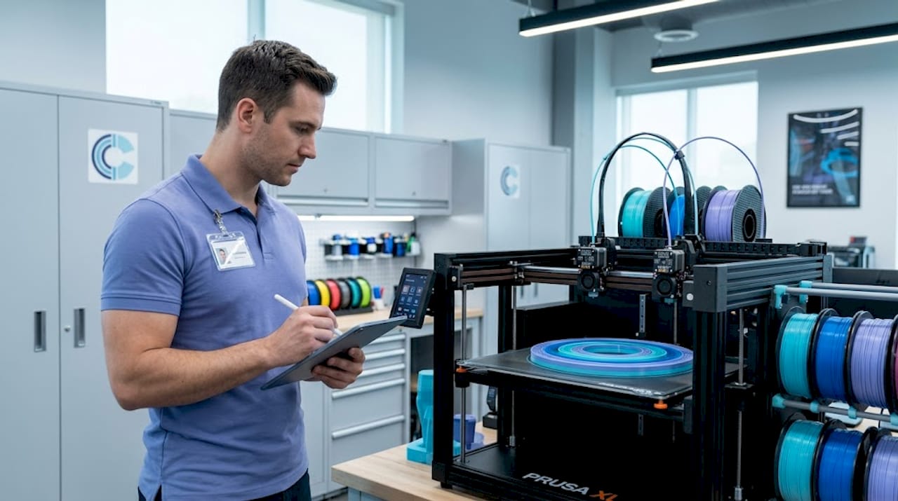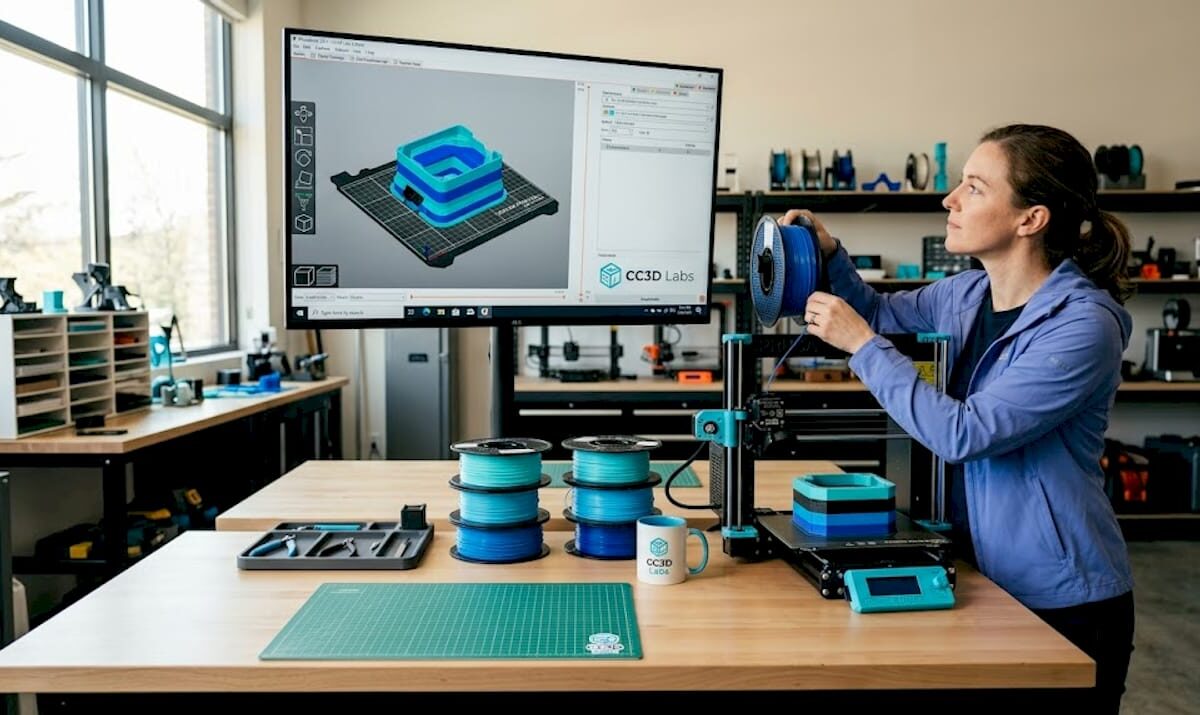
Engineer watches filament 3D printer in workshop

Filament 3D printing: Guide for prototyping success


TL;DR:

  • Filament 3D printing is a versatile and capable rapid prototyping platform, not just a hobbyist tool.
  • Proper optimization of materials, design orientation, and parameters can produce strong, functional parts suitable for engineering use.
  • Expert support and understanding of process fundamentals can significantly improve print quality and part performance.

Filament 3D printing gets dismissed as a hobbyist tool far too often. That reputation is outdated and, frankly, costly for any engineer or product developer who buys into it. When you understand the mechanics, material science, and parameter logic behind this process, it becomes one of the most capable rapid prototyping platforms available. This article walks you through how the process works, the complete production workflow, how to choose the right material, how design decisions affect part strength, and how to troubleshoot the most common failures that slow teams down.

Table of Contents

Key Takeaways

Point Details
Layer-by-layer process Filament 3D printing forms objects from melted thermoplastic extruded and fused in sequential layers.
Material selection matters Different filaments like PLA, ABS, and reinforced composites deliver unique properties for prototyping and production.
Design and settings impact strength Orientation, infill, and printing parameters determine mechanical performance and reliability of parts.
Troubleshooting addresses defects Careful adjustment of temperature, retraction, and moisture solves common printer issues like stringing and warping.
FDM is underrated With thoughtful optimization, filament 3D printing rivals high-end methods for low-volume functional prototypes.

How filament 3D printing works

At its core, filament 3D printing is a layer-by-layer extrusion process using heated thermoplastic. A spool of solid plastic filament feeds into a heated nozzle, melts, and gets deposited onto a build platform in precise paths. Each deposited layer fuses to the one below it, and the object builds up from the bottom. It sounds simple. The engineering behind it is anything but.

The nozzle diameter controls resolution and throughput. Standard sizes range from 0.2mm for fine detail work up to 0.8mm for fast structural prints. Layer heights typically fall between 0.1mm and 0.3mm, and print speeds run from 30mm/s for precision work to 100mm/s for draft parts. These three variables interact constantly, and tuning them for your specific material and geometry is where real control begins.

Understanding the 3D printing hardware components helps you make better decisions at every stage. The key hardware breaks down like this:

  • Extruder: Drives the filament forward. Direct drive extruders sit on the printhead and give better control over flexible materials. Bowden setups place the motor remotely, reducing moving mass for faster speeds.
  • Hotend: Melts the filament at a controlled temperature. The heat break separates the melt zone from the cold zone to prevent jamming.
  • Build platform: The surface where parts form. Heated beds reduce warping on materials like ABS and PETG.
  • Motion system: Controls printhead movement in X, Y, and Z axes. CoreXY and bed-slinger configurations each have speed and accuracy trade-offs.

Key components include the extruder, hotend, build platform, and motion system, and each one influences print quality in ways that compound quickly. A well-calibrated machine with mediocre filament will outperform a premium machine running wet or off-spec material every time.

Hand adjusting 3D printer hotend on bench

The FDM extrusion process follows a logical sequence: model creation, slicing into toolpaths, filament extrusion through the nozzle, and layer-by-layer deposition until the part is complete. Each step has failure points. Knowing where they are is the first step to avoiding them.

Parameter Typical range Effect on output
Nozzle diameter 0.2 to 0.8mm Detail vs. speed
Layer height 0.1 to 0.3mm Surface quality vs. print time
Print speed 30 to 100mm/s Accuracy vs. throughput
Bed temperature 0 to 110°C Adhesion and warping control

With fundamentals established, it’s important to understand the typical workflow for engineers using filament 3D printing.

The complete workflow: From digital model to physical part

The workflow involves creating a 3D model in STL or OBJ format, slicing it into G-code, feeding filament, melting and extruding, and depositing layers until the part is complete. Each step has real decisions attached to it.

  1. Model creation: Your part starts in CAD software. SolidWorks, Fusion 360, and Onshape are common choices for engineering-grade work. Export as STL or OBJ. Choosing best CAD file formats for your workflow matters more than most engineers realize, especially when tolerances are tight.
  2. Slicing: Import your model into slicing software like Cura or PrusaSlicer. The slicer converts geometry into G-code, the machine-readable instruction set that tells the printer exactly where to move, how fast, and at what temperature. This is where you set layer height, infill, supports, and wall count.
  3. Printer preparation: Load your filament, confirm bed leveling, and set your temperature profiles. A poorly leveled bed is one of the most common causes of first-layer failure. Most modern printers offer automatic mesh bed leveling, but manual verification still matters for critical prints.
  4. Extrusion and deposition: The printer executes the G-code. The nozzle traces each layer path while depositing molten plastic. Cooling fans solidify each layer before the next one lands on top.
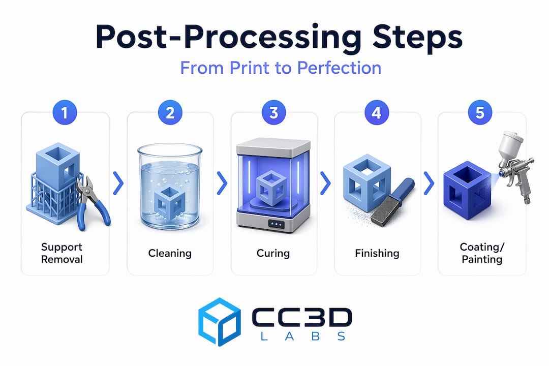
  5. Post-processing: Remove the part, strip supports, and inspect. Depending on your application, you may sand, prime, or perform secondary machining.

The filament extrusion process details show how tightly each step connects to the next. A poor model creates slicer problems. A bad slice creates print failures. A miscalibrated printer wastes both.

Pro Tip: Always dry hygroscopic filaments like Nylon and PETG before printing. Even a few hours of ambient exposure causes moisture absorption, which shows up as bubbling, rough surfaces, and inconsistent extrusion. A food dehydrator at 65°C for four hours works well. Also tune retraction carefully, typically 0.5 to 6mm depending on your extruder type, to eliminate stringing between features.

With the workflow clear, the choice of filament material is a critical next step for prototyping and production.

Choosing the right filament material: Options and trade-offs

Common materials include PLA, ABS, PETG, TPU, Nylon, PC, and carbon fiber composites, and each one brings a different set of properties to the table. Picking the wrong one for your application costs time and money.

Material Strength Heat resistance Ease of use Best for
PLA Moderate Low (50-60°C) Very easy Visual prototypes, concept models
ABS Good Moderate (80-100°C) Moderate Functional housings, enclosures
PETG Good Moderate (70-80°C) Easy Food-safe parts, mechanical use
TPU Flexible Low to moderate Moderate Gaskets, grips, flexible components
Nylon High High (120°C+) Difficult Load-bearing, wear parts
PC Very high Very high (130°C+) Difficult Structural, high-temp applications
Carbon fiber composite Very high High Moderate Lightweight structural parts

For early-stage concept models, PLA is hard to beat. It’s cheap, easy to print, and produces clean surfaces for stakeholder reviews. The moment your prototype needs to survive real-world loads, temperatures, or chemical exposure, you need to move up the material stack.

Infographic 3D printing workflow step overview

For a deeper breakdown, the material comparison guide covers mechanical properties in practical terms. If your parts will live outdoors, the outdoor filament options page is worth reviewing before you commit to a material.

The FDM material guide reinforces that material selection is application-driven, not preference-driven. Key considerations:

  • Thermal environment: Will the part see temperatures above 60°C? PLA will fail. PETG, ABS, Nylon, or PC are better choices.
  • Mechanical loading: Static display or dynamic stress? Nylon and carbon fiber composites handle cyclic loads far better than PLA.
  • Chemical exposure: Oils, solvents, moisture? PETG and Nylon resist many common chemicals.
  • Print difficulty: Tight deadline, limited calibration time? Stick to PLA or PETG.

Pro Tip: For functional low-volume parts, carbon fiber reinforced filaments and PC deliver the best strength-to-weight performance. Always dry these materials before printing, as moisture ruins dimensional accuracy and surface quality in high-performance filaments far faster than it does in PLA.

Knowing your material options, the next consideration is how design and print parameters impact the finished part’s properties.

Design and print parameters: Impact on strength and quality

Parts are anisotropic, meaning build orientation and infill pattern critically affect mechanical properties. This is the single most important concept for engineers to internalize before designing for filament printing.

Anisotropy means your part is not equally strong in all directions. Layers bond well within the XY plane but the Z-axis bond between layers is always the weak point. A part loaded perpendicular to its layers will fail earlier than one loaded parallel to them. Design with this in mind from the start.

“70 to 100% infill maximizes mechanical properties. PLA achieves ultimate tensile strength of 38 to 47 MPa at print temperatures of 195 to 220°C.”

Infill pattern and density directly control internal strength. Common options:

  • Gyroid: Excellent for isotropic strength and fluid flow applications.
  • Triangle: Efficient for flat load distribution.
  • Octet: High stiffness, good for structural brackets and fixtures.
  • Grid: Fast to print, adequate for non-critical parts.

Orientation is a design decision, not a printer setting. When you design a load-bearing bracket, orient it so the primary load path runs along the XY plane. Avoid thin vertical walls in the Z direction for structural parts.

For parameter tuning, use a design of experiments (DOE) approach. Vary one parameter at a time: temperature, speed, cooling, and wall count. Print small test coupons before committing to a full run. This saves material and time.

Choosing the right print type for prototypes depends heavily on these parameters. For parts that need to meet real performance specs, engineering-grade prints with optimized settings are the right call. The anisotropy and infill effects on finished parts are well-documented and should drive your parameter choices.

Finally, understanding common printing challenges and how to resolve them is critical for achieving consistent results.

Troubleshooting and optimizing: Common pitfalls and solutions

Stringing, oozing, diameter variance, humidity, and warping are the most common failure modes in filament printing. Each has a clear cause and a clear fix.

  1. Stringing and oozing: Caused by excess heat or insufficient retraction. Reduce print temperature by 5 to 10°C and increase retraction distance. Travel speed also matters. Faster travel gives the molten plastic less time to drip.
  2. Under-extrusion: Usually a partial clog, worn drive gear, or incorrect flow rate. Check filament diameter. Ideal tolerance is ±0.02mm. A filament that measures 1.78mm instead of 1.75mm will cause consistent under-extrusion.
  3. Over-extrusion: Too much material per move. Calibrate your extruder steps-per-mm and run a flow rate test before printing functional parts.
  4. Warping on large parts: Heated bed, enclosure, and brim settings all help. ABS and Nylon are the worst offenders. A 100 to 110°C bed and enclosed build chamber reduce warping significantly.
  5. Moisture-related defects: Bubbling, rough surfaces, and weak layers all point to wet filament. Dry your spools before every critical print run.

For stringing solutions, the fix is almost always a combination of temperature reduction and retraction tuning. For on-demand print troubleshooting, working with an experienced service provider eliminates most of these variables before your parts even start printing.

Pro Tip: Small parameter tweaks solve most problems. A 5 to 10°C temperature drop, a retraction adjustment of 0.5 to 6mm, and a travel speed increase of 20mm/s will resolve the majority of stringing and surface quality issues without requiring a full recalibration.

Why filament 3D printing is underestimated for functional prototyping

Most engineers who write off filament printing for functional work have never actually optimized it. They ran a part at default settings, saw weak layer lines, and moved on. That’s a methodology failure, not a technology failure.

FDM is best for low-volume functional prototypes when strength is prioritized through deliberate design choices. The teams that get real value from filament printing treat it like any other manufacturing process: they design for its constraints and exploit its strengths.

The biggest missed opportunity is ignoring anisotropy at the design stage. When you orient parts correctly, use reinforced filaments, and dial in wall thickness and infill, the results surprise people. We have seen carbon fiber PETG parts replace machined aluminum fixtures in low-load applications. That is not a fluke. It is the result of treating parameter optimization seriously.

Rapid iteration is where filament printing genuinely has no peer at the early hardware stage. You can go from a revised CAD file to a testable part in hours. No tooling, no lead time, no minimum order. For print terminology for engineers who are new to this space, understanding the vocabulary of the process is the first step toward using it strategically.

Pro Tip: Incorporate thicker perimeter walls (3 to 5 shells), use gyroid or octet infill at 40 to 60%, and always dry your filament. Those three changes alone can double the effective strength of a printed functional prototype.

Get expert support for filament 3D printing projects

Filament 3D printing rewards knowledge and punishes guesswork. If you are working on a prototype that needs to perform, not just look good, the material, parameter, and design decisions covered here are exactly where professional support adds the most value.

https://cc3dlabs.com

At CC 3D Labs, we work with product developers and engineers on professional 3D printing services that go beyond basic output. From material selection to parameter optimization and production-ready tolerances, we handle the variables so you can focus on your design. Whether you are exploring parts you can print for the first time or need reliable on-demand prototypes for an active development cycle, we are ready to help. Reach out for a free estimate and let’s build something that works.

Frequently asked questions

What is the difference between FDM and FFF in filament 3D printing?

FDM and FFF are essentially the same material extrusion process but with different names. FDM is a trademarked term, while FFF (Fused Filament Fabrication) is the open-source generic version used across the broader community.

How do I avoid stringing in filament 3D prints?

Reduce printing temperature, increase retraction distance, and raise travel speed. Retraction of 0.5 to 6mm combined with a 5 to 10°C temperature drop resolves most stringing issues without affecting overall print quality.

Which filament material is best for low-volume functional prototypes?

Carbon fiber composites and PC deliver the highest strength for demanding applications. PLA works for non-structural prototypes, but reinforced filaments are the right choice when parts need to survive real-world loading.

Why are 3D printed parts weaker in the Z direction?

Parts are stronger in XY than in Z because inter-layer bonding is mechanically weaker than in-plane deposition. Design your parts so primary loads run along the XY build plane to avoid inter-layer failure.

How do I store filament to prevent humidity issues?

Store filament in airtight containers with desiccant packs. Humidity affects filament flow and causes bubbling, rough surfaces, and weak layer bonding, so dry box storage is essential for hygroscopic materials like Nylon, PETG, and PC.

Engineer examines 3D printed prototypes at workbench

Choose the right 3D printing type for prototypes & production


TL;DR:

  • Selecting the appropriate 3D printing process based on project needs is crucial to avoid costly rework.
  • FDM is cost-effective for prototypes and fixtures but has limitations in accuracy and strength direction.
  • Resin-based methods like SLA/DLP excel in surface finish and detail, suitable for visual prototypes and casting masters.

Choosing the wrong 3D printing process can cost you weeks of rework and thousands in wasted material. For product developers moving from concept sketches to functional prototypes and into low to mid-volume production, the stakes are real. FDM, SLA, SLS, MJF, DMLS — each process delivers a different combination of accuracy, surface finish, material strength, and cost per part. Pick the wrong one and your prototype won’t test what you need it to test. This guide breaks down every major printing type, the technical benchmarks that separate them, and a clear framework for matching process to project goals.

Table of Contents

Key Takeaways

Point Details
Selection framework Match print process to function, tolerance, strength, and finish for best results.
FDM for prototypes FDM/FFF offers the lowest cost and largest build volumes for design validation and jigs.
SLA/DLP for detail SLA and DLP provide the finest accuracy and smoothest surface for visual prototypes.
Powder bed for function SLS/MJF excel in functional nylon parts and DMLS/SLM leads for metal.
Comparison tools Use quick-reference tables to compare tolerances, properties, and applications for each 3D printing type.

How to evaluate 3D printing types: Key criteria

Before comparing technologies, you need a structured way to filter them. The right process depends on a combination of factors, and skipping this step leads to expensive mismatches between what the print can deliver and what your part actually needs.

Here are the core criteria to assess before selecting a process:

  • Intended function: Is this a visual mock-up, a fit/form check, a functional stress test, or an end-use production part?
  • Mechanical properties: Tensile strength, flexural modulus, impact resistance, and isotropy all vary significantly by process.
  • Surface finish: Measured in Ra (roughness average), finish affects aesthetics, sealing, and post-processing requirements.
  • Dimensional tolerance: Critical for mating parts, press fits, and precision assemblies.
  • Part size: Build envelope limits differ widely — FDM machines can print large enclosures; resin printers are typically smaller.
  • Material options: Engineering polymers, flexible TPU, high-temp resins, metal alloys — process determines what’s available.
  • Budget and volume: Cost per part drops with some processes at volume; others stay flat.

A useful way to think about this: tolerance requirements alone can cut your list in half. Types of 3D printing for prototypes and production show that SLA achieves ±0.05mm, SLS and MJF land around ±0.2–0.25mm, and FDM typically runs ±0.5mm. If your part has tight mating tolerances, FDM is off the table immediately.

Anisotropy — the directional difference in mechanical strength — is another filter most teams miss early. Parts printed in FDM are significantly weaker in the Z direction. SLS and MJF are near-isotropic, meaning strength is consistent regardless of build orientation. Understanding this upfront shapes not just process selection but also part orientation strategy.

Post-processing needs matter too. Sanding, priming, dyeing, and support removal all add time and cost. Knowing how to pick the right process before you send a file saves iterations. For early-stage teams, a solid quick prototyping guide can clarify how process selection ties directly to development speed.

Extrusion-based printing (FDM/FFF): Workhorse for prototypes and jigs

FDM (Fused Deposition Modeling) and its open-source counterpart FFF (Fused Filament Fabrication) work by melting a thermoplastic filament and depositing it layer by layer. The process is straightforward, scalable, and compatible with a wide range of engineering-grade materials including PLA, PETG, ABS, ASA, Nylon, TPU, and high-temp options like PEEK.

Strengths of FDM for engineering applications:

  • Lowest cost per part among all major processes
  • Widest range of build volumes — some industrial FDM machines exceed 1,000mm in a single axis
  • Broad material library with well-documented mechanical properties
  • Fastest turnaround for large, low-detail parts

Limitations to plan around:

  • Visible layer lines require sanding or coating for smooth surfaces
  • Z-axis weakness due to layer adhesion — parts can delaminate under load
  • Tolerances of ±0.5mm limit use in precision assemblies

FDM is the cost-effective choice for jigs, fixtures, enclosures, and early-stage prototypes where geometry validation matters more than surface quality. The FDM process mechanics — including temperature control, support structures, and layer adhesion — are well understood, which makes troubleshooting predictable.

“FDM gives development teams the fastest path from CAD to physical object at a price point that supports multiple design iterations without budget pressure.”

Pro Tip: Reorienting a part 45 degrees and adjusting infill pattern can boost effective tensile strength by up to 20% without changing material or process. This is one of the most underused levers in FDM design.

For teams choosing between materials, understanding the tradeoffs between FDM materials like PLA, PETG, and ABS directly affects whether the prototype survives functional testing or fails at the first load cycle.

Professional comparing FDM 3D printing materials

Photopolymerization (SLA/DLP): Precision and surface detail

SLA (Stereolithography) uses a UV laser to cure liquid resin point by point, while DLP (Digital Light Processing) flashes an entire layer at once using a projector. Both produce parts with exceptional surface quality, but the mechanics create meaningful differences in speed and accuracy.

Key advantages of resin-based printing:

  • Surface finish as low as Ra 1–3µm — the smoothest of any common 3D printing process
  • SLA achieves ±0.05mm tolerance, DLP typically ±0.10mm
  • Excellent for fine features, thin walls, and complex organic geometry
  • Ideal for casting masters, dental models, and visual presentation prototypes

Where resin processes fall short:

  • Most standard resins are brittle and not suited for load-bearing applications
  • UV exposure over time degrades mechanical properties — outdoor use is limited
  • Build volumes are smaller than FDM, limiting large-part applications
  • Post-curing is required, which adds time and affects final properties

A 2025 flexural study found SLA flexural strength at 93MPa, outperforming DLP at 70MPa — a meaningful gap when you’re validating parts that need to flex under load. DLP’s speed advantage makes it attractive for batch runs of small, detailed parts where per-layer cure time is the bottleneck.

Pro Tip: Post-curing under controlled UV exposure increases hardness and flexural strength, but over-curing increases brittleness. Run a calibration cure test on sample parts before committing to a full batch.

For teams who need to communicate surface finish definitions to clients or manufacturing partners, understanding Ra values and how they map to process output prevents misaligned expectations at review.

Powder bed fusion (SLS, MJF, DMLS/SLM): From functional polymers to metal parts

Powder bed fusion covers a family of processes that fuse material layer by layer from a powder bed. No support structures are needed for polymers — the surrounding powder acts as support — which enables highly complex geometries that other processes can’t achieve.

SLS (Selective Laser Sintering) uses a CO2 laser to sinter nylon powder. It produces parts with ±0.25mm tolerance and tensile strength around 48MPa for PA12. Parts are durable, chemically resistant, and suitable for functional testing and low-volume production runs.

MJF (Multi Jet Fusion) uses inkjet-deposited fusing agents activated by infrared energy. It’s faster than SLS, produces denser parts, and achieves near-isotropic mechanical properties — meaning orientation during printing has minimal effect on strength. This matters enormously for end-use parts.

DMLS/SLM uses a fiber laser to fuse metal powder — titanium alloys, stainless steel, Inconel, aluminum. Parts reach >99.5% density with tolerances of ±0.10mm, making them viable for aerospace, medical, and industrial end-use applications.

Powder bed processes offer the best combination of geometric freedom and mechanical isotropy for functional polymer and metal parts — a combination no other process family can match at this scale.

Process Tolerance Key material Relative cost Best use case
SLS ±0.25mm PA12 Nylon Medium Functional prototypes, low-run production
MJF ±0.20mm PA12, PA11 Medium-high End-use parts, near-isotropic loads
DMLS/SLM ±0.10mm Ti6Al4V, steel High Metal qualification, aerospace, medical

For teams working on functional polymer and metal prints, SLS and MJF are often the bridge between prototype validation and production-ready components. The SLS and MJF mechanics — including powder management, thermal stress, and post-processing — require more process knowledge than FDM but reward that investment with significantly better part performance.

Quick reference comparison: Picking the right 3D printing process

With all four major process families covered, here’s a consolidated view for engineering teams making a final call.

Process Tolerance Surface finish Cost tier Production fit
FDM ±0.5mm Moderate (Ra 10–20µm) Low Prototypes, jigs, fixtures
SLA ±0.05mm Excellent (Ra 1–3µm) Medium Visual prototypes, casting masters
DLP ±0.10mm Excellent (Ra 1–3µm) Medium Detailed small parts, dental
SLS/MJF ±0.20–0.25mm Good (Ra 6–10µm) Medium-high Functional parts, low-volume runs
DMLS/SLM ±0.10mm Good (Ra 4–10µm) High Metal end-use, qualification parts

Based on tolerance and cost benchmarks across processes, here are scenario-based recommendations:

  1. Visual prototype for stakeholder review: Use SLA or DLP. Surface quality and accuracy make the part presentation-ready without secondary finishing.
  2. Fit and form check on an assembly: FDM is fast and cheap enough to iterate. If tolerance is critical, step up to SLA.
  3. Functional part for stress or environmental testing: SLS or MJF. Near-isotropic nylon parts survive real-world loads and chemicals.
  4. Metal part qualification for production: DMLS/SLM. The density and tolerance match machined metal for most non-critical applications.
  5. Special cases: Binder Jetting works well for full-color models and metal sintering at lower cost than DMLS. PolyJet handles multi-material and overmold simulations. Both are worth considering when standard processes don’t fit.

Exploring real-world 3D printing applications across industries shows how these process choices play out in practice. For teams ready to act, reviewing on-demand project examples gives a concrete sense of what each process delivers at production scale.

Our take: Why context matters more than specs in 3D printing selection

Datasheets are a starting point, not a decision. We’ve seen engineers spend weeks comparing tolerance specs between SLS and MJF for a prototype that only needed to survive two weeks of fit testing. The 0.05mm difference was irrelevant. What mattered was turnaround time and cost per iteration.

The limitations people worry about most — anisotropy in FDM, brittleness in SLA resins — are often manageable with smart design choices. Anisotropy becomes an advantage when you orient a part so the load direction aligns with the strongest axis. Resin brittleness stops being a problem when the part is a casting master, not a structural component.

Our honest advice: run a test iteration before committing to a process for a full batch. A single test print reveals more than any datasheet. And revisit process selection as your design matures. What works for a first-round prototype often isn’t the right call for a 500-unit production run. Focus on fit-for-purpose, and let the design evolution guide the process evolution. For teams navigating that transition, working through bespoke 3D print jobs with experienced partners accelerates that learning significantly.

Get expert 3D printing for your next project

At CC 3D Labs, we work with product developers and engineers across every stage of the product lifecycle — from first-round prototypes to low and mid-volume production runs. Whether you need FDM for rapid iteration, SLA for presentation-quality parts, or specialty materials for functional testing, we match the process to your actual requirements, not just the closest available option.

https://cc3dlabs.com

We handle custom material requests, multi-color printing, and CAD support for teams that need more than a file upload and a quote. If you’re unsure which process fits your current project, explore our 3D printing services or browse what parts are printable for your application. Ready to move? Submit your file and project details through our on-demand custom projects page for a fast, accurate estimate.

Frequently asked questions

Which 3D printing type delivers the strongest mechanical properties for end-use parts?

SLS and MJF produce near-isotropic nylon parts that approach injection-molded strength, while DMLS/SLM yields metal components with greater than 99.5% density for demanding structural applications.

What are the main limitations of FDM versus SLS or SLA?

FDM is weaker along the Z axis and shows visible layer lines, while SLS offers better isotropy and SLA provides the best surface finish but lower load-bearing capacity. Each process has tradeoffs that make it better suited for specific applications.

How do I choose the best 3D printing type for visual prototypes?

SLA delivers the finest detail and smoothest surface finish for visual prototypes, making it the top choice when appearance and dimensional accuracy are the primary goals.

Are 3D printed materials suitable for outdoor or high-temperature use?

Engineering polymers like PEEK and metals like Ti6Al4V handle high temperatures reliably, but SLA resins degrade under prolonged UV exposure and are not recommended for outdoor applications without protective coating.

Can powder bed fusion create both polymer and metal parts?

Yes. SLS and MJF process nylon and other polymer powders for durable functional parts, while DMLS and SLM fuse metal powders to produce dense, high-strength metal components.

Engineer comparing PLA PETG ABS parts in lab

PLA vs PETG vs ABS: Best Material for Durable Parts


TL;DR:

  • PETG outperforms ABS in impact resistance with 15-20% higher impact cycles before failure.
  • Material choice depends on operating environment, with PETG suitable for impact and chemical exposure.
  • Proper print parameters and part design are critical to ensure functional part reliability, not just material selection.

Most engineers assume ABS is the toughest material for functional 3D printed parts. That assumption has cost real projects real money. Recent bracket testing found that PETG survived 15-20% more impact cycles than ABS before failure, which forces a rethink of the default material hierarchy. Choosing between PLA, PETG, and ABS is not just a spec-sheet exercise. It involves understanding how each material behaves under real stress, how print settings amplify or undermine those properties, and how your part geometry interacts with the material’s natural weaknesses. This article gives you a practical, data-backed framework to make that call with confidence.

Table of Contents

Key Takeaways

Point Details
PETG excels in impact PETG outperforms ABS and PLA in real-world impact tests for brackets and functional parts.
Design affects strength Print settings like infill and orientation matter as much as material choice for part durability.
No universal best Optimal material depends on use case, required heat resistance, and specific application demands.
Expert guidance helps Consulting material and process experts prevents costly failures in functional 3D prints.

Understanding PLA, PETG, and ABS: Properties and applications

Before running any stress test, you need a clear picture of what each material actually offers. Knowing the 3D printing terms that describe material behavior will help you read data sheets and supplier claims more critically.

PLA (Polylactic Acid) is the easiest of the three to print. It runs at lower temperatures, sticks well to most build surfaces, and produces minimal warping. Tensile strength is competitive, often reaching 50-65 MPa in solid form. The catch is brittleness: PLA fails suddenly under impact rather than deforming, and its heat deflection temperature sits around 50-60°C, which rules it out for any part near a heat source.

Infographic comparing key PLA PETG ABS features

PETG (Polyethylene Terephthalate Glycol) sits in a practical middle ground. It is tougher and more ductile than PLA, offers solid chemical resistance to many common solvents, and handles temperatures up to roughly 80°C. It bonds well between layers, which reduces the anisotropy risk that plagues many FDM parts. Print settings are a bit more demanding than PLA but far more forgiving than ABS.

ABS (Acrylonitrile Butadiene Styrene) brings the highest heat resistance of the three, with a deflection temperature around 100°C, and it machines and post-processes well. The tradeoffs are real: ABS requires an enclosure to prevent warping, emits fumes that need ventilation, and shows weaker interlayer adhesion than PETG under certain loading conditions.

Here is a quick reference for the three materials:

Property PLA PETG ABS
Tensile strength (solid) 50-65 MPa 45-55 MPa 40-50 MPa
Heat deflection temp ~55°C ~80°C ~100°C
Impact resistance Low High Moderate
Print difficulty Easy Moderate Hard
Chemical resistance Low Moderate Moderate
Cost Low Moderate Moderate

Common applications break down like this:

  • PLA: Concept models, low-stress fixtures, display parts, short-run jigs
  • PETG: Functional brackets, fluid-contact parts, snap-fit assemblies, enclosures
  • ABS: Under-hood automotive components, electrical housings, parts requiring acetone smoothing

One critical point that many teams overlook: strength in FDM depends heavily on print parameters like infill and layer orientation, not just the raw material. Solid material tensile values are a starting point, not a guarantee. Following material selection best practices before committing to a filament can prevent expensive redesigns later.

Pro Tip: Before finalizing your material, ask whether your part will face chemical exposure or sustained heat. If yes, PLA is almost certainly off the table, and the real decision is between PETG and ABS based on your temperature ceiling.

Mechanical performance: Real-world testing and data

With a clearer understanding of the base properties, it is important to examine how these materials actually behave in real functional stress scenarios.

The most telling data point for product developers is impact performance. In controlled bracket testing, PETG outperformed ABS by 15-20% in impact cycle counts before failure. That is not a marginal difference. For parts that experience repeated loading, vibration, or drop risk, PETG is the more reliable choice despite ABS’s reputation.

Technician testing 3D printed part strength

Infill geometry matters more than most teams realize. Hexagonal infill at 30% density produced a PETG tensile strength of 18.54 MPa in standardized testing, outperforming rectilinear and triangular patterns at the same density. That means you can hit stronger results without increasing material use, simply by changing the infill pattern in your slicer.

Here is how the three materials compare in key functional metrics:

Test condition PLA PETG ABS
Impact resistance Brittle, sudden failure High, ductile deformation Moderate
Layer adhesion Good Excellent Fair to good
Warping risk Very low Low High
Post-failure behavior Shatters Deforms Cracks/splits
Thermal cycling stability Poor Good Good

PLA’s failure mode is the most dangerous for functional parts. It does not warn you. It holds load until it does not, then fractures cleanly. For printed functional parts that carry real mechanical loads, that sudden failure mode is a liability.

To maximize performance from whichever material you choose, follow this process:

  1. Set infill to hexagonal or gyroid pattern for load-bearing parts
  2. Orient the part so the primary stress axis runs parallel to layer lines, not perpendicular
  3. Increase wall count to at least 3 perimeters for structural sections
  4. Run a short print at reduced scale to validate failure mode before full production
  5. Test at actual operating temperature, not just room temperature

Matching these settings to your specific application is exactly the kind of decision that separates a successful run from a costly reprint. Reviewing guidance on matching print jobs to needs before you start slicing is time well spent. For deeper context on industrial prototyping best practices, external resources can fill in the gaps your material data sheet leaves open.

Beyond the material’s properties, how you print and design your part is just as critical.

FDM parts are inherently anisotropic. That is not a flaw to work around; it is a reality to design for. As FDM anisotropy research confirms, tensile values from solid material samples do not translate directly to printed parts because layer bonding creates directional strength differences. A part that tests at 50 MPa in the XY plane may perform at 30 MPa or less when loaded in the Z direction.

Key design decisions that directly affect part reliability:

  • Wall thickness: Thicker walls reduce the impact of infill anisotropy and improve load distribution. For structural parts, 2.0-3.0 mm minimum wall thickness is a practical baseline.
  • Geometry: Avoid sharp internal corners. They concentrate stress and are where layer-bonded parts crack first. Add fillets wherever load paths change direction.
  • Orientation: Print the part so the weakest bond direction (Z axis) is not aligned with the primary load. This single decision often matters more than material choice.
  • Support strategy: Poorly supported overhangs create surface defects that act as stress risers. Plan your orientation to minimize support contact on functional surfaces.

The most common mistake we see is engineers treating a 3D printed part like a machined one. The geometry looks the same, but the internal structure is completely different. Design for the process, not just the shape.

For teams working from existing CAD files, reviewing optimized CAD workflows for FDM can catch design issues before they become print failures. If you are reverse-engineering an existing part, high quality 3D scans give you accurate geometry to work from rather than guessing at tolerances.

Pro Tip: Always prototype in the exact print orientation you plan to use in production. A part that passes testing in one orientation can fail quickly when reoriented, even with identical settings.

A solid 3D print checklist before each production run catches the parameter drift that causes batch failures.

Choosing the right material for your functional part

Armed with print and performance knowledge, it is time to decide which material best fits your project.

Start with the operating environment. Temperature, chemical exposure, and mechanical loading type are your three filters. Apply them in that order and your material options narrow quickly.

Here is a decision matrix built for functional parts:

Requirement Best choice Why
Heat above 80°C ABS Highest deflection temp
Repeated impact loads PETG 15-20% more impact cycles vs ABS
Chemical exposure PETG Better solvent resistance than PLA
Low cost prototyping PLA Easiest to print, lowest cost
Acetone smoothing needed ABS Only material that responds to acetone
Snap-fit assemblies PETG Ductility prevents brittle snap failure

Use this numbered checklist to streamline your material selection process:

  1. Define the maximum operating temperature your part will face
  2. Identify any chemical or fluid contact requirements
  3. Classify the load type: static, cyclic, or impact
  4. Determine whether post-processing (smoothing, painting, threading) is required
  5. Set your cost and lead time constraints
  6. Cross-reference against the decision matrix above

For on-demand production examples that show how these decisions play out across real part types, reviewing actual project outcomes is more instructive than spec sheets alone. If you are producing prototypes and repair parts under tight timelines, having a clear material brief before you engage a print service cuts revision cycles significantly.

Pro Tip: Factor in post-processing before you lock in your material. ABS is the only one of the three that smooths with acetone vapor, which can matter for sealing surfaces or cosmetic requirements. PETG resists most adhesives, which affects assembly planning.

A manufacturer’s perspective: What most comparisons miss

Most material comparison articles stop at the spec table. That is where the real problems begin.

After working through hundreds of functional part projects, the pattern is clear: material choice causes far fewer failures than print tuning and part design. We have seen PETG parts fail in applications where PLA would have worked fine, simply because the infill was set to rectilinear at 15% and the wall count was two. The material was not the problem. The process was.

The other consistent mistake is ignoring the actual use environment during testing. A bracket that passes a static load test on a workbench will behave very differently when it is mounted in a vibrating enclosure at 70°C. Engineers often validate under ideal conditions and then wonder why field failures happen.

Material selection is a starting point, not a solution. The real work is in aligning material, process, and design to the specific demands of the application. Specialty material projects that push beyond standard filaments make this even more apparent: the process discipline required for high-performance materials exposes every shortcut taken with common ones.

No single material wins every application. The engineers who get consistent results are the ones who treat material, settings, and design as one integrated decision, not three separate checkboxes.

Get expert help with functional 3D printing

Getting material selection right is only the first step. Translating that choice into a reliable, production-ready part requires process expertise that goes well beyond slicer defaults.

https://cc3dlabs.com

At CC 3D Labs, we work with product developers and manufacturing teams to match material, print parameters, and part design to your specific functional requirements. Whether you are evaluating materials for a new bracket design or scaling a prototype to batch production, our team provides hands-on guidance at every stage. Our 3D printing services cover everything from initial material consultation to final part delivery, with fast turnaround and quality you can measure. Explore our on-demand printing solutions to get started with a free estimate today.

Frequently asked questions

Which material is most durable for functional parts: PLA, PETG, or ABS?

PETG typically outlasts both ABS and PLA in impact-heavy applications, with 15-20% more impact cycles before failure in controlled bracket testing. For parts facing repeated loading, PETG is the stronger default choice.

When should I pick PLA over PETG or ABS?

Choose PLA for functional prototypes where ease of printing, low cost, and moderate strength are the priorities and the part will not face sustained heat above 55°C or significant impact loading.

Does infill pattern really affect part strength?

Yes, significantly. FDM strength depends on infill pattern and print orientation, not just material, because printed parts show directional strength differences that solid material values do not capture.

Which material is best for high temperature environments?

ABS offers the highest heat deflection temperature of the three, around 100°C, making it the right choice for parts exposed to sustained elevated temperatures where PETG or PLA would deform.

Designer reviews 3D-printed parts at workspace

Top 4 Xometry 3D Printing Alternatives 2026

The search for reliable 3D printing services keeps growing as more people and businesses look for quality, speed, and affordable options. With so many platforms offering different features and pricing structures, finding the right fit can be both exciting and challenging. Some focus on producing complex parts while others aim for fast delivery or personalized support. The variety can feel overwhelming but also opens the door to new possibilities. What happens when you compare some leading choices head to head

Table of Contents

CC 3D Labs

Product Screenshot

At a Glance

CC 3D Labs is the clear, top-tier choice for businesses and product developers who need precise, reliable filament based 3D printing and professional scanning near Philadelphia. Their combination of quality prints, fast turnarounds, and local pickup with worldwide shipping makes selection easy.

Core Features

CC 3D Labs specializes in filament based 3D printing, 3D scanning, and CAD services for prototypes, functional parts, and batch production. They provide multi color and multi material printing, metrology grade scanning, on demand manufacturing, and hands on design support.

Pros

  • Wide material selection: They print with advanced filaments including specialty materials so you can test functional properties and cosmetic finishes in one shop.

  • Integrated scanning and CAD: Metrology grade scanning plus 3D modeling and CAD services speed iteration and reduce back and forth with external vendors.

  • Fast local turnaround: Local service near Philadelphia shortens review cycles and supports quick iterative testing for time sensitive projects.

  • International shipping options: You get local pickup when convenient and shipping worldwide when projects scale beyond the region.

  • Free estimates and support: Free online estimates and service support lower your procurement friction and help plan budgets before committing.

Who It’s For

If you are a product developer, a small manufacturer, or a business needing reliable prototypes and production parts with quick iteration cycles, CC 3D Labs fits your workflow. You benefit most when accuracy, material variety, and fast feedback matter.

Unique Value Proposition

CC 3D Labs pairs professional, high quality printing with metrology grade scanning and in house CAD services so you receive end to end support from concept to verified part. Their emphasis on durable, accurate parts and multi color, multi material options gives you both functional testing and production ready finishes. Local presence near Philadelphia speeds turnaround and enables hands on collaboration while worldwide shipping and batch production capability allow scale. The result is an industry leading mix of technical precision, practical speed, and design support that smart buyers choose when project risk and time are critical.

Real World Use Case

A product developer in Philadelphia uses CC 3D Labs for rapid prototyping of enclosures and mechanical parts, harnessing multi material printing to test seals and mounts, then using metrology grade scanning for repeatable verification before moving to small batch production.

Pricing

Pricing details are not published on the site; customers request a free quote to get project specific pricing. That approach lets CC 3D Labs tailor estimates to materials, print resolution, and batch size.

Website: https://cc3dlabs.com

Xometry

Product Screenshot

At a Glance

Xometry is a platform for on demand custom manufacturing that serves startups through global enterprises with fast quoting and broad process coverage. Its bottom line: reliable digital workflows and a large supplier network for prototypes and production.

Core Features

Xometry offers instant quoting through the Instant Quoting Engine and supports diverse manufacturing methods including CNC machining, 3D printing, and Injection Molding. The platform pairs quotes with a global network of certified suppliers and a resource center for design guidance.

Pros

  • Fast, reliable quoting: The Instant Quoting Engine gives immediate price and lead time feedback so you can plan procurement without waiting for manual estimates.
  • Wide process and material selection: The platform supports multiple manufacturing methods and materials that scale from prototypes to production runs.
  • Scalable capacity: Suppliers in the network allow you to move from single prototypes to high volume production without changing platforms.
  • Certified quality standards: Xometry reports quality controls and certifications such as ISO 9001:2015 that support traceability for regulated industries.
  • Transparent digital workflows: Order tracking and supplier communication provide traceability and centralized documentation for manufacturing projects.

Cons

  • The platform assumes familiarity with manufacturing terms which can create a learning curve for users new to fabrication.
  • Pricing depends on part complexity and volume so detailed estimates often require direct consultation for accurate budgeting.
  • The service model limits physical interaction since work happens through the platform and partner shops rather than a single local facility.

Who It’s For

Xometry suits manufacturers, product designers, startups, and large enterprises that need fast, reliable access to multiple manufacturing processes. If you manage prototypes, bridge to production, or require certification backed suppliers, this platform fits those workflows.

Unique Value Proposition

Xometry combines automated quoting and a global supplier network to reduce sourcing friction for custom parts. That pairing lets businesses shorten lead times while keeping options open for materials, processes, and production scale.

Real World Use Case

A product team needing rapid prototyping and subsequent metal or plastic production receives instant quotes, selects a manufacturing method, and shifts to higher volume suppliers within the same platform. The result is fewer vendor handoffs and clearer timelines.

Pricing

Pricing is project dependent and generated per part or assembly through instant quotes. You get an immediate estimate on submission and can request detailed quotes or consultations for complex geometries or larger volume runs.

Website: https://xometry.com

Protolabs

Product Screenshot

At a Glance

Protolabs is a digital manufacturing provider focused on rapid prototyping and low volume production with a strong emphasis on automation and speed. It fits businesses that need quick turnarounds and consistent quality from prototype to short run production.

Core Features

Protolabs provides fast online quoting and automated order processing paired with Design for Manufacturability analysis to catch issues early. The platform supports injection molding, CNC machining, 3D printing, and sheet metal fabrication with real time pricing and a broad material selection.

Pros

  • Highly automated process: Automation reduces manual steps so orders move from upload to production faster than traditional suppliers.

  • Quick turnaround times: Many orders complete in days which shortens development cycles for product teams and engineers.

  • Wide service offering: The mix of injection molding, CNC, 3D printing, and sheet metal covers prototyping and low volume production needs.

  • Built in design feedback: DFM guidance helps catch manufacturability issues before parts reach the shop floor which lowers rework risk.

  • Global digital factories: Multiple production sites allow distributed manufacturing and can reduce shipping time for international projects.

Cons

  • Requires CAD files for best results: The platform performs best when you supply fully finished CAD which can be a barrier for early concept work.

  • Less personal touch for complex jobs: Heavy reliance on the digital platform means highly custom or artisanal projects receive less bespoke interaction.

  • Higher pricing for some low volumes: Very low volume runs or highly complex parts can be more expensive compared with handcrafted local shops.

Who It’s For

Protolabs suits engineers, product developers, and manufacturers who prioritize speed, repeatability, and traceable feedback during design validation. Teams that need functional prototypes and quick small batch production will get the most value from the service.

Unique Value Proposition

Protolabs combines instant quoting, process automation, and DFM feedback to deliver predictable lead times and fewer surprises. That combination turns iterative product development into a faster, more measurable workflow for engineering teams.

Real World Use Case

A startup developing a consumer electronic device uploads final CAD and uses Protolabs to produce functional prototypes for user testing. After validation the same service moves the design into low volume injection molding for an initial production run.

Pricing

Pricing varies based on material, process, complexity, and volume with quotes generated instantly online. Project teams can get immediate cost visibility which helps compare options during design reviews.

Website: https://protolabs.com

Fictiv

Product Screenshot

At a Glance

Fictiv provides a managed digital manufacturing platform that moves projects from prototype to production with speed and visibility. Its strength lies in instant quoting and a vetted global network that supports CNC, 3D printing, injection molding, and sheet metal.

Fast. Clear. Traceable.

Core Features

The platform delivers DFM feedback during quoting, order tracking, and regionally diverse sourcing to control lead times and tariffs while supporting prototyping through full production. The interface bundles manufacturing options and partner selection into one control layer.

  • Instant quoting and automated DFM analysis
  • Access to CNC machining, 3D printing, injection molding, and sheet metal
  • Global partner network for regional sourcing and lead time management
  • Order tracking and supply chain visibility from prototype to production

Pros

  • Rapid turnaround: Prototype parts can ship in as little as one day and CNC in two days, which speeds design iterations.
  • Platform visibility: An integrated digital platform gives you real time order status and design for manufacturability feedback.
  • Diverse capabilities: Wide manufacturing options reduce the need to manage multiple vendors for different processes.
  • Supply chain options: Regional sourcing helps manage tariffs and lead times when scaling internationally.
  • Technical support: Expert consultation and DFM guidance help refine parts for manufacturability before committing to production.

Cons

  • The platform has a learning curve, and new users may spend time mastering partner selection and workflow settings.
  • Service availability and lead times vary by region, which can cause unpredictability for international projects.
  • Pricing requires upload and quoting, so upfront cost transparency is limited until specifications are submitted.

Who It’s For

Engineers, product designers, startups, and small to medium sized manufacturers that need a single partner for rapid prototyping and short run production will benefit most. Teams that prioritize speed, traceability, and design feedback gain immediate value.

Unique Value Proposition

Fictiv pairs a digital quoting and DFM workflow with a curated manufacturing network, so you get both immediate cost estimates and production options in one place. That combination reduces coordination overhead and shortens development cycles.

Real World Use Case

A hardware startup uses Fictiv to prototype enclosure parts, receives DFM feedback to correct wall thickness and tolerances, and then converts the same supply path to small volume production while managing cross border sourcing to lower tariff impact.

Pricing

Pricing is quote based and generated after uploading CAD files and selecting process options, which makes costs specific to geometry, material, and volume. Requesting an instant quote reveals lead times and a tailored price for each part.

Website: [https://fictiv.com]

Comprehensive Product Comparison: 3D Printing and Custom Manufacturing Services

This table provides a detailed comparison of several notable 3D printing and custom manufacturing service providers, outlining their key features, target industries, unique strengths, and pricing considerations to aid in making an informed choice.

Service Provider Key Features Pros Cons Pricing
CC 3D Labs Filament-based 3D printing, CAD services, metrology-grade scanning Wide material selection, local services with international shipping, integrated scanning and CAD design Limited to their stated range of manufacturing techniques Quote-based, tailored per project
Xometry CNC machining, 3D printing, injection molding with global supplier network Instant quoting, scalability, certified quality standards Limited physical interaction, complex pricing clarity Pricing generated per project via the Instant Quoting Engine
Protolabs Automated quoting, design feedback, CNC machining, 3D printing, sheet metal fabrication Fast and automated processes, design guidance High pricing for low-volume projects, less personal interaction Immediate online quotes based on specifications
Fictiv DFM feedback, diverse global network, quick prototyping capabilities Regionally diverse sourcing, rapid part delivery Steep learning curve for inexperienced users Instant quotes based on uploaded designs

Discover Reliable 3D Printing Alternatives with CC 3D Labs

If you found yourself exploring top Xometry 3D printing alternatives it likely means you need a partner who offers precise and custom filament-based 3D printing with fast turnaround times. Many businesses and product developers face challenges like managing project timing, ensuring high quality, and accessing multi-material options without sacrificing local support or international shipping. CC 3D Labs specializes in overcoming these pain points with metrology-grade scanning and expert CAD services that speed up your product iteration cycle.

https://cc3dlabs.com

Explore why clients near Philadelphia trust CC 3D Labs for durable prototypes, batch production, and personalized design support. Act now to get your free estimate and benefit from a seamless balance between technical precision and practical speed. Visit CC 3D Labs to start elevating your projects today.

Frequently Asked Questions

What are the top alternatives to Xometry for 3D printing in 2026?

CC 3D Labs, Protolabs, and Fictiv are among the top alternatives that provide various 3D printing services. Evaluate their core features to determine which aligns best with your project needs and timelines.

How does pricing compare between Xometry and its alternatives?

Pricing varies significantly among 3D printing services, often based on materials and complexity. Request free quotes from multiple providers to compare project-specific costs and ensure you stay within budget.

What types of 3D printing technologies do these alternatives offer?

Most alternatives offer diverse 3D printing technologies including filament-based printing, CNC machining, and injection molding. Review each service’s capabilities to select the right technology based on your prototyping or production requirements.

How quickly can I receive prototypes from these Xometry alternatives?

Turnaround times vary, but many services like Protolabs and Fictiv can deliver prototypes within a few days. Choose a provider that prioritizes speed to match your project timelines.

Do these alternatives provide design feedback before printing?

Yes, several providers, including Protolabs and Fictiv, offer Design for Manufacturability (DFM) feedback. Utilize this service to catch potential issues early in the design process, reducing the risk of rework later on.

Is it possible to scale production with these 3D printing alternatives?

Yes, most alternatives support low-volume production and can scale to higher quantities if needed. Confirm with your chosen provider to ensure they can accommodate your growth plans while maintaining quality.