

TL;DR:
- Drafting standards in 3D modeling establish rules for communicating design intent, geometry, and tolerances across workflows. They enable precise, unambiguous data exchange and prevent costly manufacturing errors by ensuring models are inspection-ready and organized properly. Enforcing these standards through software tools and workflow integration is essential for reliable, production-ready 3D models.
Drafting standards in 3D modeling are defined rule sets that govern how design intent is communicated, measured, and verified across every stage of a production workflow. These standards cover geometric dimensioning and tolerancing (GD&T), CAD data organization, and interoperability protocols. The two most referenced frameworks are ASME Y14.5, which defines symbolic tolerancing language for manufacturing, and ISO 10303 (STEP), which governs cross-platform data exchange. Without these standards, a model that looks correct on screen can produce parts that fail inspection on the shop floor.
What are drafting standards in 3d modeling?
Drafting standards in 3D modeling are the formal rules that define how geometry, dimensions, tolerances, and annotations are structured inside a CAD file. The industry term for this discipline is model-based definition (MBD), and it represents a shift away from 2D drawing packages toward fully annotated 3D models. CAD standards cover both appearance conventions such as layers, dimension styles, and symbols, and data organization rules that determine how files are named, structured, and exported.

A common misconception is that these rules are primarily about visual consistency. The real value lies in precise, unambiguous communication of size, shape, and tolerances that enables reliable manufacture and inspection. When a machinist or a coordinate measuring machine (CMM) reads a model, every symbol must carry exactly one interpretation. Ambiguity at this stage translates directly into scrap, rework, and cost overruns.
For 3D designers and engineers, understanding drafting standards means recognizing two parallel layers of rules. The first layer is semantic: GD&T symbols, datum references, and tolerance callouts. The second layer is structural: file naming, layer organization, metadata, and export format. Both layers must be correct for a model to move cleanly through a CAD modeling workflow.
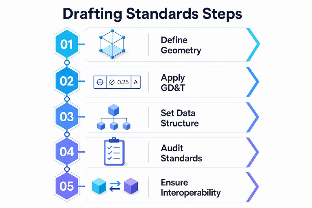
Gd&t, data structure, and annotations explained
Geometric dimensioning and tolerancing (gd&t)
GD&T is the symbolic language that turns design intent into quantifiable requirements. ASME Y14.5 is the dominant standard in North America, and it defines symbols for flatness, cylindricity, true position, runout, and more than a dozen other geometric characteristics. Each symbol attaches a specific, measurable meaning to a feature. That specificity is what allows a CMM to verify a part automatically without a human interpreter.
MBD workflows embed these GD&T annotations directly into the 3D model as Product Manufacturing Information (PMI). Embedding PMI in 3D models enables CAD, PLM, CAM, and metrology systems to read design intent identically without intermediate translation. This eliminates the version-control problem that plagues organizations still maintaining parallel 2D drawing sets.
Pro Tip: When setting up PMI in software like Siemens NX or PTC Creo, attach every tolerance to a named datum reference frame from the start. Retrofitting datum structure onto a finished model costs far more time than building it correctly upfront.
CAD data structure and naming conventions
Data structure rules govern how a model is organized inside the file and across a project directory. Standard conventions include layer naming schemas, block or component naming, line weight assignments, and metadata fields like revision number and material specification. The National CAD Standard (NCS) and ISO standards both provide frameworks for these conventions, improving consistency and enabling data exchange between organizations.
Poorly organized CAD data passes visual checks but fails downstream. A model with correct geometry but misnamed layers or missing metadata will break automated manufacturing and inspection pipelines. Splitting standards into semantic rules (GD&T) and data-structure rules prevents this failure mode.
How CAD software enforces drafting standards
CAD platforms provide built-in tools to apply and audit drafting guidelines for 3D workflows. The enforcement mechanism matters as much as the standard itself. A style guide that lives in a PDF and is never checked produces inconsistent results across a team.
Autodesk AutoCAD uses standards files with the .DWS extension to enforce layer names, text styles, dimension styles, and line type properties. CAD standards auditing checks active drawings against these files and flags or automatically corrects any deviation. This workflow prevents standards drift in multi-user environments where individual designers make local modifications over time.
Here is how a typical CAD standards enforcement workflow runs in AutoCAD:
- A standards administrator creates a
.DWSfile that defines approved layers, styles, and properties for the project. - The
.DWSfile is distributed to all team members and linked to active drawing files. - Designers run the
CHECKSTANDARDScommand to audit their work before submission. - AutoCAD flags non-conforming elements and offers automatic fixes where the correction is unambiguous.
- A project lead reviews the audit report and approves the file for release.
Pro Tip: Schedule automated standards checks as part of your file-save routine using AutoCAD’s notification settings. Catching a layer naming error at save time takes seconds. Catching it after a file has been handed to manufacturing takes hours.
The real power of drafting standards comes from enforceability through software auditing and team discipline, not from style guides alone. Organizations that rely on documentation without automated checks consistently produce non-conforming files.
Why interoperability standards matter for 3d collaboration
ISO 10303 (STEP) and cross-platform data exchange
ISO 10303, universally known as STEP, is the international standard for exchanging product model data across CAD, CAM, CAE, and PDM systems. STEP subdivides into approximately 700 standards and supports long-term archival as well as system-independent 3D model exchange. That breadth makes it the default format for aerospace, automotive, and defense supply chains where multiple organizations use different CAD platforms.
STEP preserves both geometry and topology, but semantic data preservation requires additional care. A model exported from CATIA and imported into SolidWorks may retain its surfaces while losing PMI annotations if the application protocol (AP) does not support that data scope. Interoperability depends on exporter and importer behavior and must be verified at each step in the toolchain.
Comparing key interoperability standards
| Standard | Primary Use | Data Preserved | Industry Focus |
|---|---|---|---|
| ISO 10303 (STEP) | Cross-platform CAD exchange | Geometry, topology, PMI (AP-dependent) | Aerospace, automotive, defense |
| IFC (ISO 16739) | Building and infrastructure models | Geometry, spatial relationships, metadata | Architecture, engineering, construction |
| IGES | Legacy geometry exchange | Geometry only | General manufacturing (legacy) |
| OBJ / FBX | Visualization and rendering | Geometry, color, UV maps | Media, gaming, visualization |
For architecture, engineering, and construction (AEC) workflows, IFC (Industry Foundation Classes) fills the same role that STEP fills in mechanical engineering. IFC carries spatial relationships, component metadata, and building system data that STEP does not address. Choosing the wrong format for your industry means losing the semantic layer that makes a model useful beyond simple geometry.
Validating standards compliance at every handoff point is non-negotiable. Run format validation tools before sending files to partners or manufacturers. A translation error discovered after a part is machined is far more expensive than one caught during file review. For a practical look at CAD file format selection, the format choice directly affects how much of your standards-compliant data survives the transfer.
Best practices for production-ready 3d models
Drafting standards address how design intent is communicated. Production modeling standards address whether the geometry itself is manufacturable and pipeline-ready. Both sets of rules must be satisfied for a model to move from design to physical output without rework.
Professional 3D modeling standards emphasize clean topology, polygon efficiency, consistent edge flow, proper UV unwrapping, and the elimination of non-manifold geometry. These requirements apply whether the output is a rendered animation, a CNC toolpath, or a 3D print. Non-manifold geometry, for example, causes slicer software to fail silently, producing prints with missing walls or internal voids.
A production-ready model checklist covers the following areas:
- Topology: Use quads as the primary polygon type. Triangles are acceptable at termination points. N-gons cause shading artifacts and should be resolved before export.
- Scale and units: Set the correct real-world scale before modeling begins. A part modeled at the wrong unit system will print at the wrong size even if the geometry is perfect.
- Naming conventions: Name every component, material, and UV channel descriptively. Generic names like “Mesh001” create confusion in assembly files and pipeline handoffs.
- Non-manifold geometry: Run a manifold check in tools like Meshmixer, Netfabb, or the slicer’s built-in repair function before finalizing any model intended for physical production.
- File organization: Group components logically, purge unused assets, and save in the format required by the downstream tool.
| Quality Check | Tool | Pass Criteria |
|---|---|---|
| Manifold geometry | Meshmixer, Netfabb | Zero open edges or non-manifold faces |
| Scale verification | CAD software ruler | Matches engineering drawing dimensions |
| Naming convention | Manual review or script | All objects follow project naming schema |
| PMI completeness | CAD PMI manager | All features have tolerance callouts |
These production standards integrate directly with drafting standards. A model with correct GD&T annotations but broken topology will still fail at the manufacturing stage. End-to-end quality assurance requires both layers to be correct. For engineers focused on tolerances in 3D printing, the connection between GD&T callouts and physical print accuracy is direct and measurable.
Key takeaways
Drafting standards in 3D modeling require both semantic precision (GD&T and PMI) and structural discipline (data organization and interoperability) to produce models that are reliable from design through manufacturing.
| Point | Details |
|---|---|
| GD&T is the core semantic layer | ASME Y14.5 symbols turn design intent into machine-readable, verifiable requirements. |
| MBD replaces 2D drawings | Embedding PMI directly in 3D models eliminates ambiguity and version-control problems. |
| Software enforcement is mandatory | AutoCAD .DWS auditing and similar tools prevent standards drift across multi-user teams. |
| STEP governs data exchange | ISO 10303 preserves geometry and PMI across platforms, but AP compliance must be validated. |
| Production standards complete the picture | Clean topology, correct scale, and organized assets are required alongside drafting rules for production-ready output. |
Where standards break down in real projects
Most standards failures I see at Cc3dlabs do not come from ignorance of ASME Y14.5 or ISO 10303. They come from the gap between knowing a standard and enforcing it consistently across a team under deadline pressure. A designer who understands GD&T perfectly will still skip datum references when a project is running late. That shortcut costs far more time downstream than it saved upfront.
The shift toward MBD is real and accelerating, but it creates a new failure mode. Teams that move tolerances and annotations from 2D drawings into 3D PMI sometimes assume the software handles validation automatically. It does not. PMI that is geometrically attached but semantically incomplete passes visual inspection and fails CMM verification. I have seen this exact problem delay production runs by days.
My practical recommendation is to treat standards enforcement as a workflow step, not a final review. Build .DWS checks, manifold validation, and PMI completeness reviews into the save and submit process. Make them automatic and non-optional. The teams that do this consistently produce fewer non-conforming files and spend less time on rework. The teams that treat standards as a checklist item at the end of a project spend a disproportionate amount of time fixing problems that were created weeks earlier.
The future of 3D design drafting rules points toward tighter integration between CAD, 3D printing, and metrology. As CAD integration drives printing precision, the standards embedded in your model become the direct input to both the printer and the inspection system. Getting those standards right is not a documentation exercise. It is the foundation of a reliable production process.
— Justin
How Cc3dlabs supports standards-compliant 3d production
When your model meets drafting and production standards, the path from file to finished part is fast and predictable. Cc3dlabs works with engineers and product developers near Philadelphia and worldwide to turn standards-compliant CAD files into precise, functional parts. The team reviews incoming models for production readiness, flags geometry issues before printing begins, and delivers parts that match the tolerances specified in your design.

Whether you need a single prototype or a batch production run, Cc3dlabs’ 3D printing services are built around the same quality standards covered in this guide. From filament-based FDM parts to metrology-grade 3D scanning, every project starts with a free online estimate and direct design support. Submit your file and get a quote today.
FAQ
What are drafting standards in 3d modeling?
Drafting standards in 3D modeling are formal rule sets that govern how geometry, dimensions, tolerances, and annotations are structured in a CAD file. They include GD&T frameworks like ASME Y14.5 and data organization conventions that ensure models are clear, consistent, and production-ready.
What is gd&t and why does it matter for 3d models?
GD&T (Geometric Dimensioning and Tolerancing) is a symbolic language defined by ASME Y14.5 that communicates exact size, shape, and tolerance requirements for manufactured parts. It matters because it replaces ambiguous notes with machine-readable symbols that CMMs and CAM software can interpret without human interpretation.
What is the difference between STEP and IGES for CAD data exchange?
STEP (ISO 10303) preserves geometry, topology, and PMI annotations depending on the application protocol used, making it the current standard for cross-platform exchange. IGES is a legacy format that transfers geometry only and lacks support for semantic data like tolerances and metadata.
How does model-based definition (MBD) change drafting workflows?
MBD embeds GD&T annotations and PMI directly into the 3D model, eliminating the need for separate 2D drawing packages. This reduces ambiguity and allows CAD, CAM, and metrology systems to read design intent from a single source of truth.
What tools enforce CAD drafting standards across a team?
AutoCAD uses .DWS standards files to audit layer names, text styles, and dimension properties against approved project standards. Running the CHECKSTANDARDS command flags and corrects non-conforming elements before files are released to manufacturing or shared with collaborators.