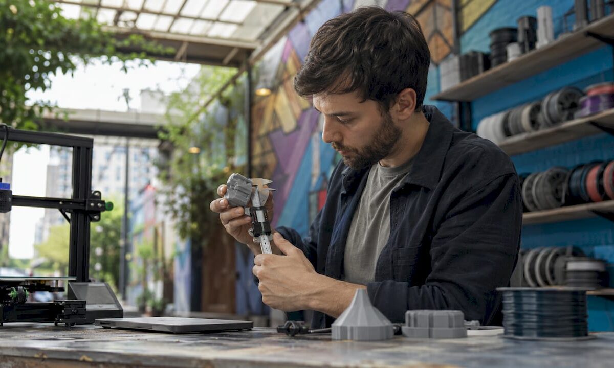
Teacher guiding students at classroom 3D printer

Harnessing 3D Printing in Education: Transform Student Learning


TL;DR:

  • 3D printing significantly improves student understanding and engagement in STEM subjects.
  • Successful integration relies on curriculum-first planning, teacher training, and proper workflow.
  • Common challenges include high costs, resource management, and curriculum alignment, but solutions exist.

A recent pre-post study with 32 Grade 6 students found significant academic gains in space science after using 3D-printed models, and that result should make every educator pause. 3D printing in schools is no longer a novelty reserved for tech showcases or maker fairs. It has become an evidence-based instructional tool that strengthens student understanding, sharpens problem-solving, and bridges the gap between abstract content and hands-on discovery. This guide walks educators and administrators through the research, the practical frameworks, the real challenges, and the curriculum strategies that make 3D printing actually work in learning environments.

Table of Contents

Key Takeaways

Point Details
3D printing boosts engagement Integrating 3D printing increases student engagement and skill development in STEM and beyond.
Teacher preparation is key Educator training and curriculum-first planning enable effective and sustainable classroom integration.
Overcome barriers wisely Address cost, training, and durability challenges with evidence-backed, practical solutions and material choices.
Focus on learning goals Success comes from aligning technology with meaningful curriculum objectives, not just using flashy tools.

The evolution of 3D printing in education

Early 3D printers entered schools as expensive curiosities. They sat in corners of computer labs, printed plastic trinkets, and impressed visitors at open houses. Teachers rarely had time to integrate them meaningfully, and students used them for show rather than learning. That era is largely behind us.

Over the past decade, falling hardware costs, open-source design software, and a strong push toward project-based learning (PBL) and challenge-based learning (CBL) shifted the role of the printer from novelty to instructional asset. PBL asks students to investigate real-world problems and create tangible outputs. CBL pushes them further, requiring them to tackle an authentic challenge with measurable results. In both models, a physical, touchable prototype is far more powerful than a slide deck.

The S.T.E.M. emphasis in K-12 and higher education also accelerated adoption. Schools needed tools that connected science, technology, engineering, and mathematics in visible, tactile ways. A 3D-printed model of a cell, a bridge stress-test prototype, or a scaled architectural model does exactly that.

Key drivers behind classroom adoption include:

  • Project-based and challenge-based learning requiring physical deliverables
  • S.T.E.M. curriculum mandates that reward cross-disciplinary application
  • Lower-cost FDM printers (FDM stands for fused deposition modeling, the most common filament-based printing method) making entry more accessible
  • Open-source design tools like Tinkercad and Fusion 360 reducing the design learning curve
  • Maker culture normalizing fabrication as a core academic skill

The TPACK framework (Technological Pedagogical Content Knowledge) has become a critical guide for teacher professional development. TPACK helps educators think about three overlapping skill areas: knowing the technology, knowing how to teach, and knowing the subject matter. When schools train teachers using TPACK, they produce instructors who can confidently connect the printer to a learning objective rather than using it as a standalone activity.

Research confirms the pattern. A systematic review of 20 studies on 3D printing in teacher education found that while the technology clearly enhances skill development and student engagement, schools consistently face challenges around resource availability, time constraints, and curriculum integration.

“The technology is not the lesson. The lesson is the lesson. 3D printing is a powerful vehicle, but only when the driver knows where they’re going.”

For those curious about what creative 3D printing applications look like in practice, the range is genuinely surprising, from working mechanical assemblies to anatomical models that students can hold and examine.

How 3D printing transforms learning outcomes

Evidence for measurable gains keeps building. In the Grade 6 space science study mentioned earlier, students who used 3D-printed models of planets, lunar phases, and orbital systems scored significantly higher on post-tests than they did on pre-tests. The models gave abstract content a physical form. Students could rotate, compare, and manipulate objects that would otherwise exist only as textbook images.

Students studying 3D-printed spacecraft model

At the university level, the impact shifts slightly. Rather than boosting content recall, 3D printing in higher education tends to strengthen design thinking, iterative problem-solving, and the connection between theoretical knowledge and functional prototypes. Engineering programs that integrate challenge-based learning with 3D prototyping report improvements in prototype quality alongside stronger critical thinking and creativity outcomes.

Here is a snapshot of documented outcomes across educational levels:

Setting Subject area Outcome measured Finding
Grade 6 K-12 Space science Academic performance Significant pre-post improvement
University engineering Mechanical design Prototype quality, creativity Improved with CBL integration
Teacher education Cross-disciplinary Skill development, engagement Enhanced, with noted resource challenges
Secondary STEM Physics/engineering Spatial reasoning Measurably improved

Beyond academic scores, students who work with 3D printers regularly develop skills that traditional instruction struggles to build. These include:

  • Spatial reasoning, the ability to mentally rotate and visualize objects in three dimensions
  • Iterative design thinking, understanding that a first attempt is a starting point, not a final product
  • Technical communication, translating an idea from words to a CAD model that a machine can execute
  • Material awareness, learning how real-world choices like wall thickness and infill density affect function

Prioritizing quality in educational 3D prints matters more than many educators initially expect. A poorly printed model with visible layer delamination or warped geometry can actually confuse students rather than help them. When the physical artifact is accurate and well-made, the learning it enables is far more reliable.

Key stat: The Grade 6 study used a structured pre-post test design, one of the strongest formats for measuring actual learning gains, making its findings more credible than typical anecdotal classroom reports.

Implementing 3D printing: Practical methods and proven frameworks

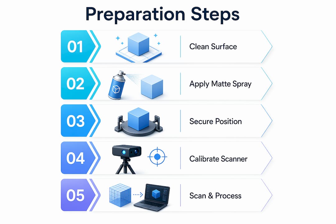
Moving from theory to practice requires a clear process. Most successful classroom implementations follow a consistent workflow that educators can adapt regardless of subject area or grade level.

  1. Define the learning objective first. Before anyone opens design software, identify what students need to understand or be able to do. The print should serve the objective, not the other way around.
  2. Model and design. Students create or modify a 3D model using tools like Tinkercad (beginner-friendly) or Fusion 360 (more advanced). This stage builds CAD literacy and spatial thinking.
  3. Slice the model. Slicing software (such as Cura or PrusaSlicer) converts the 3D design into printer instructions. Students learn about layer height, print speed, support structures, and infill, all legitimate engineering considerations.
  4. Print and evaluate. The physical object emerges, and students immediately compare it against their intentions. Does it match? If not, why? What would they change?
  5. Iterate. Redesign based on findings. This is where the deepest learning happens, when students treat failure as data.

This workflow maps naturally onto both PBL and CBL frameworks. In PBL, students might design a water filtration prototype over several weeks. In CBL, they might be given a specific structural challenge, like building a bridge that holds a set weight using minimal material, and iterate until they meet it.

The TPACK model recommends that teacher training programs focus on design intent and materials science alongside printer operation. A teacher who understands why a model is printed a certain way can guide students far more effectively than one who only knows how to press “print.”

For higher education specifically, DfAM (Design for Additive Manufacturing) coursework offered by organizations like ASTM International and Wohlers Associates provides a rigorous, industry-aligned curriculum framework that engineering departments can integrate directly.

Approach Best for Key benefit Limitation
PBL (Project-Based Learning) K-12 through undergrad Authentic deliverables, sustained engagement Requires significant planning time
CBL (Challenge-Based Learning) University engineering Real constraints, iterative improvement Needs access to reliable printers
TPACK-driven PD Teacher training Balances tech, pedagogy, and content Requires ongoing professional development
DfAM coursework Higher education Industry-ready skills, materials knowledge Specialized, less accessible for K-12

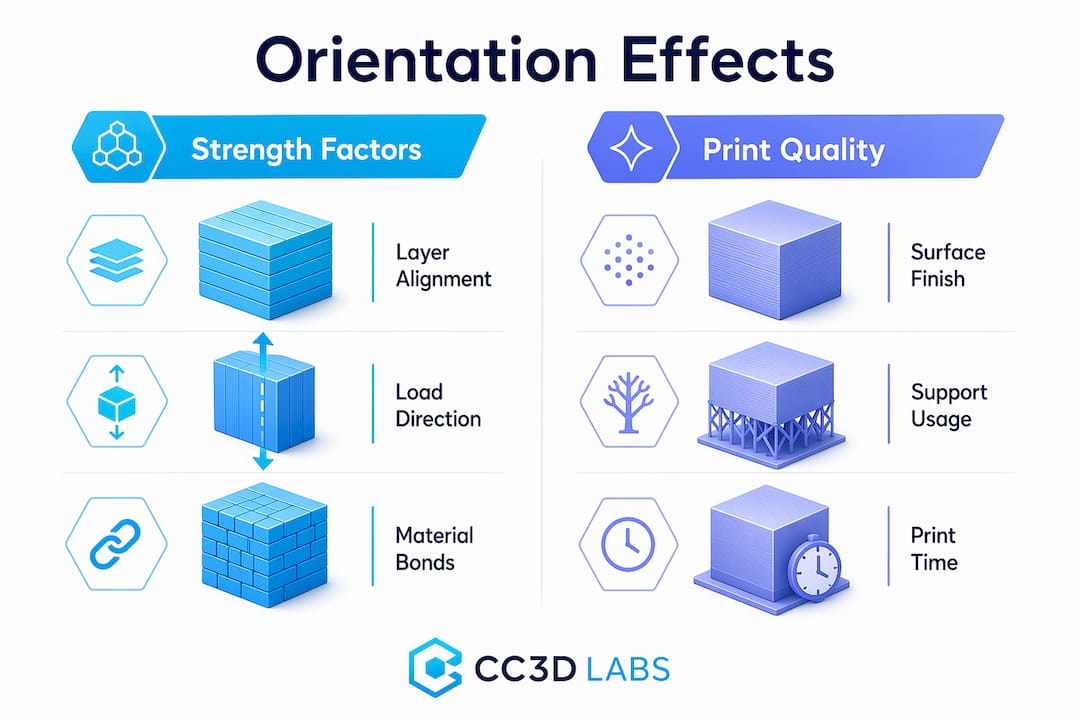
Pro Tip: When designing reliable prints for classroom use, orient models to minimize overhangs and maximize contact with the build plate. This reduces failed prints dramatically, which is critical when class time is limited.

Infographic illustrating quality tips for classroom 3D prints

Choosing classroom 3D printing materials is equally important. PLA is beginner-friendly and biodegradable, making it a sensible starting point. PETG offers better durability and impact resistance for models students will handle frequently. ABS is harder to print reliably without an enclosure and is better suited to university engineering labs than middle school classrooms.

Real-world challenges and sustainable solutions

The research is clear, and the frameworks are solid. But every administrator knows that implementation is where the best plans meet real friction. Understanding the most common barriers lets you address them before they derail your program.

School 3D printing challenges documented in research include:

  • High upfront cost for hardware, filament, and software licenses
  • Insufficient teacher training, leaving educators unsure how to connect printing to curriculum
  • Equipment maintenance, as consumer-grade printers require regular calibration and part replacement
  • Time pressure, since even a small print can take 30 to 90 minutes, creating scheduling challenges
  • Model fragility, where thin-walled or poorly designed prints break during normal classroom handling
  • Curriculum misalignment, where printing becomes a standalone activity disconnected from learning standards

Each of these has a practical solution.

For cost, start with one or two reliable FDM printers rather than a lab full of cheaper units. A single, well-maintained Prusa or Bambu machine produces better outcomes than five poorly supported alternatives. Apply for S.T.E.M. grants, many of which specifically list additive manufacturing as a fundable technology.

For teacher training, invest in hands-on workshops before any printer arrives. Teachers who have designed, sliced, and printed something themselves before teaching it are far more confident and effective. Schedule dedicated prep time in the weeks before launch.

For maintenance, designate a student “print crew” or a faculty tech lead responsible for machine upkeep. Clear protocols for calibration, bed leveling, and nozzle cleaning extend printer lifespan significantly.

For model fragility, material selection for durability is the first line of defense. PETG prints tend to survive classroom handling far better than PLA when models will be passed around repeatedly. Increasing wall thickness and infill percentage in the slicing settings also improves resilience without adding major print time.

Pro Tip: Pre-slice and pre-queue print jobs during the week before a project unit. Running printers during non-class hours, overnight or on weekends, eliminates the in-class wait time problem entirely and keeps the learning momentum high.

Why a curriculum-first mindset matters for 3D printing success

Here is the uncomfortable pattern we see repeatedly: schools invest in printers, run a few exciting demo sessions, generate some social media buzz, and then watch utilization drop sharply after the first semester. The printers gather dust. Teachers feel guilty they’re not using them. The technology gets blamed.

The technology is rarely the problem. The planning is.

Most failed 3D printing programs start with the machine and work backward toward a justification. They buy the printer, then ask, “What can we print?” The better question is always, “What do students need to understand, and can a physical model help?” When the answer to that second question is yes, 3D printing becomes a powerful instructional tool. When it’s no, the printer should sit this one out.

Research reinforces this. Expert guidance on DfAM integration emphasizes curriculum-first thinking over tool-centric approaches. The most effective university programs start by teaching design intent and materials science, then introduce the printer as the tool that makes the design real. The machine serves the curriculum, not the other way around.

This mindset shift has real consequences for administrators making purchasing decisions. Before buying equipment, map out at least one full semester of curriculum units where 3D printing has a clear, documented role. Identify the learning standard, the student output, and the assessment. If you can’t fill a full semester with purposeful use, start smaller.

The creative integrations in curriculum that generate the best student outcomes share a common trait: the teacher designed the learning experience before opening any design software. The printer was the final step in a well-planned instructional sequence, not the starting point.

Students don’t benefit from 3D printing because it’s exciting. They benefit because it gives their thinking a physical form, and that physical form reveals gaps, errors, and insights that no worksheet ever could.

Explore 3D printing solutions for your school

Whether you’re building a new maker program, scaling an existing one, or looking to print higher-quality models than your current equipment allows, professional support makes a real difference.

https://cc3dlabs.com

At CC 3D Labs, we work with educators and institutions to produce precise, durable educational 3D printing applications ranging from anatomical models and engineering prototypes to visual aids and architectural scale models. Our filament-based 3D printing services for schools include multi-color prints, CAD support, and quick turnaround times that work around your academic schedule. When you need custom 3D prints that meet specific dimensional or material requirements, we can help you get them right the first time. Request a free online estimate and find out what’s possible for your program.

Frequently asked questions

What skills do students gain from 3D printing in school?

Students develop problem-solving, creativity, spatial reasoning, and design thinking, particularly in STEM subjects. Research shows that challenge-based learning with 3D printing specifically improves prototype quality and fosters iterative, critical thinking in engineering courses.

What are the biggest challenges for schools adopting 3D printing?

Key challenges include high costs, teacher training gaps, equipment maintenance, time management, and ensuring curriculum alignment. These documented barriers are consistent across K-12 and higher education settings, but each has a practical solution when addressed proactively.

How should schools train teachers for 3D printing integration?

Effective training uses hands-on workshops, curriculum-first planning, and frameworks like TPACK to build confidence and skills. Programs that follow structured teacher development methodologies produce educators who can connect the technology to specific learning outcomes rather than using it as a standalone activity.

PETG is a strong choice for school environments because it offers durability, impact resistance, and manageable print settings. Guidance for administrators recommends prioritizing PETG filament alongside accessible FDM printers for the best combination of cost-effectiveness and classroom durability.

Engineer editing CAD model in workspace

How CAD integration drives 3D printing precision


TL;DR:

  • CAD design decisions directly influence print quality, strength, and success in 3D printing.
  • Properly optimized CAD models reduce failures caused by mesh issues, overhangs, and unsupported geometries.
  • Mastering CAD workflows is more impactful for quality and efficiency than investing in expensive printers.

Even the most expensive FDM printer on the market cannot compensate for a poorly built CAD file. That counterintuitive reality catches a lot of product developers off guard, especially those who assume hardware upgrades are the fastest path to better prints. The truth is that CAD is the foundational step in every 3D printing workflow, converting your concept into a precise digital model that gets exported, sliced, and ultimately printed. Every tolerance, wall thickness, and mesh decision you make in CAD ripples forward into the physical part. Understanding that connection is what separates teams that iterate quickly from those stuck reprinting the same prototype three times.

Table of Contents

Key Takeaways

Point Details
CAD is foundational Every 3D print project’s success begins and ends with how well you design and optimize your digital CAD model.
Follow DfAM best practices Design for Additive Manufacturing rules like correct wall thickness and support planning prevent failed prints.
Optimize for performance Tweaking orientation, infill, and mesh within CAD boosts strength and reduces production time and cost.
Account for advanced issues Factoring in anisotropy and potential hybrid machining from the CAD stage yields better functional parts.
Invest in CAD expertise Skillful CAD work typically enables more innovation and reliability than investing in costly printers alone.

How CAD shapes the 3D printing process

CAD, or computer-aided design, is the software environment where your idea becomes a geometric, measurable model. It is not simply a drawing tool. In the context of 3D printing, CAD determines whether a part is even printable, and at what level of accuracy it will come out of the machine.

The workflow runs like this: you design a 3D model in CAD, export it as a machine-readable file, feed that into slicing software, and the slicer generates the toolpath your printer follows. The most common export format is STL (stereolithography), which approximates curved surfaces using triangular mesh facets. Higher triangle density produces smoother curves but inflates file size. Other formats like 3MF and STEP carry additional metadata such as color, scale, and assembly information, making them increasingly preferred for complex production jobs.

Infographic showing CAD to 3D printer workflow steps

Here is why this matters in practice. An STL file with too-low resolution will print visible faceting on a curved medical enclosure or an aerodynamic intake. A mesh with non-manifold edges, gaps, or overlapping surfaces creates ambiguous geometry that slicers interpret incorrectly, leading to missing walls or hollow sections in a part that was supposed to be solid. Understanding the best CAD file formats for your specific workflow prevents a whole category of upstream errors before you ever hit print.

What CAD controls in 3D printing:

  • Part geometry, including all wall thicknesses and internal features
  • Surface topology and mesh quality
  • Assembly fit and tolerancing
  • Export format and resolution
  • Whether geometry is valid and printable without repair

“CAD directly impacts print quality, precision, and success. The wrong design decisions create failures that no printer setting can fix.”

The key shift in mindset is treating CAD not as a design tool but as a manufacturing specification tool. Every decision you make in the model is a decision about how the printer will behave layer by layer.

Key CAD methodologies for print success

Design for additive manufacturing, commonly called DfAM, is the discipline of shaping CAD decisions around the specific constraints and advantages of 3D printing. It is distinct from design for injection molding or machining, and applying the wrong framework causes obvious problems.

The

core DfAM practices every engineer should internalize include minimum wall thickness guidelines, overhang management, hole geometry, stress-relief features, and watertight meshes. These are not aesthetic preferences. They are parameters grounded in how filament or resin behaves during deposition or curing.

Critical DfAM parameters for FDM and SLA:

  • Minimum wall thickness: 1.0 to 2.0mm for FDM, 0.5 to 1.0mm for SLA
  • Overhang angle: Keep overhangs under 45 degrees from vertical to avoid drooping without supports
  • Teardrop holes: Orient vertical holes as teardrops to eliminate bridging failure at the top
  • Fillets and chamfers: Add internal fillets to corners to reduce stress concentrations and delamination risk
  • Mesh integrity: All surfaces must form a closed, watertight volume with no holes, gaps, or non-manifold edges
DfAM Parameter FDM Guideline SLA Guideline
Minimum wall thickness 1.2 to 2.0mm 0.5 to 1.0mm
Overhang angle Less than 45° Less than 30°
Minimum hole diameter 2.0mm 0.5mm
Fillet radius 0.5mm minimum 0.3mm minimum
Mesh type Watertight, manifold Watertight, manifold

When designing reliable prints, overhang management is often where teams stumble first. A bracket arm designed without awareness of the printer’s 45 degree threshold will require heavy supports that are time-consuming to remove and often leave cosmetic or dimensional defects on the contact surface. Redesigning the arm with a chamfer instead of a perpendicular face eliminates the support entirely.

Technician inspecting 3D print overhang issues

Pro Tip: When your geometry calls for a hole parallel to the build plate, model it as a teardrop shape pointing upward. The slicer will bridge the flat underside cleanly, and you end up with a more accurate bore than a standard circle produces.

Watertight meshes deserve special attention because this is where many imported or converted models fail silently. A mesh that looks correct in CAD may contain microscopically open surfaces. Slicers either crash or generate malformed toolpaths from non-manifold geometry. Running a mesh repair check inside your CAD tool or a validator like Meshmixer before export is not optional on mission-critical parts. For more on how these rules translate into real outcomes, explore the print accuracy tips that guide our own production process.

Optimizing CAD files for stronger, more efficient parts

Once your model is geometrically sound and DfAM-compliant, the next layer of optimization focuses on performance. This is where CAD decisions directly affect mechanical strength, print time, and material cost simultaneously.

Step-by-step CAD optimization for production-ready parts:

  1. Analyze part orientation in the slicer before finalizing the model. The axis of greatest load should align with the XY build plane, not the Z axis.
  2. Identify all surfaces that would require supports and explore geometry modifications to minimize them.
  3. Choose between solid and lattice infill based on the part’s function. Load-bearing parts often need solid infill; structural housings can use gyroid or honeycomb lattice patterns without sacrificing rigidity.
  4. Set layer thickness based on your precision requirements. Thinner layers produce stronger, more accurate parts at the cost of print time.
  5. Confirm mesh resolution is high enough to accurately represent curves without over-bloating file size.
  6. Validate thermal settings in your CAD metadata or production notes if you are working with engineering-grade filaments like Nylon or PETG.

CAD pre-processing optimization analyzes part orientation to minimize supports, cut material use, and reduce print time. Tools like Siemens NX with DfAM modules can compare solid versus lattice infill configurations computationally, letting you evaluate structural performance before a single gram of filament is consumed.

The data on this is compelling. Empirical research on FDM shows that optimized CAD-printed PLA cubes reach compressive strength values around 31.4 MPa. Layer thickness is the single most influential parameter: a low layer thickness of 0.15mm combined with a high extruder temperature of 225 degrees Celsius produces the maximum combined performance index across strength and surface quality.

Configuration Layer Thickness Extruder Temp Compressive Strength
Optimized 0.15mm 225°C ~31.4 MPa
Standard 0.2mm 210°C ~24 MPa
Low quality 0.3mm 200°C ~18 MPa

This is not trivial. A 30 to 40 percent difference in part strength comes from CAD and process settings, not from switching to a more expensive printer. When you are developing functional prototypes or end-use parts, refer to manufacturing-grade methods to understand how these optimization principles apply at production scale. For teams new to this level of detail, a step-by-step prototype guide can bridge the gap between concept and validated part.

Advanced considerations: Anisotropy, lattices, and hybrid processes

For engineers pushing the mechanical limits of 3D printed parts, three topics demand serious CAD-level attention: anisotropy, lattice structure design, and hybrid manufacturing workflows.

Anisotropy refers to the directional variation in mechanical properties that FDM parts exhibit by default. Because material is deposited in layers, bonds between layers are inherently weaker than bonds within a layer. FDM anisotropy can result in a strength drop of up to 70 percent in the Z axis compared to the XY plane. In CAD terms, this means that a part carrying tensile loads in the Z direction will fail at a fraction of the force a same-geometry machined metal part would tolerate.

The CAD response to anisotropy is deliberate orientation strategy. You map the dominant load vectors onto the XY plane during the design phase, not as an afterthought during slicing. In some cases, this means splitting a part into two components that are printed separately and bonded, rather than printing a single piece in an unfavorable orientation.

Lattice structures offer compelling advantages for weight reduction in aerospace, robotics, and medical devices. A gyroid lattice can maintain 70 to 80 percent of a solid part’s stiffness at 40 percent of the material volume. However, internal lattices create a support removal challenge that most standard post-processing tools cannot address cleanly.

Key points for CAD-level lattice design:

  • Define lattice cell size relative to nozzle diameter. Cells too small for the nozzle diameter will not print accurately.
  • Avoid lattice regions adjacent to mating surfaces that require dimensional precision.
  • Include drain holes in enclosed lattice zones to allow powder or resin evacuation in SLS and SLA processes.
  • Simulate load distribution before committing to a cell pattern. Not all lattice geometries perform equally under all load types.

Pro Tip: If you are designing a lattice for structural lightweighting, run an FEA (finite element analysis) pass inside your CAD tool before exporting. Topology optimization outputs combined with lattice infill give you a data-backed starting point instead of an educated guess.

Hybrid manufacturing recognizes that 3D printing alone does not always achieve the tight tolerances that functional parts require. Post-print CNC machining on bearing surfaces, threaded holes, and mating faces is increasingly common in precision applications. This means your CAD model needs to include machining allowances, datum references for fixturing, and feature flags that differentiate printed surfaces from machined surfaces. Planning these details in CAD from the start avoids costly reprints and setup errors downstream. For guidance on balancing print complexity with production volume, the tips for low-volume production are directly applicable here.

Our take: Why great CAD still trumps expensive printers

We work with product developers and engineers across a wide range of industries, and one pattern shows up consistently: teams that struggle with print quality are almost always struggling with CAD quality first. The printer is rarely the problem. A printer running with a well-optimized, DfAM-compliant file will outperform a top-shelf machine running a poorly constructed model every single time.

The uncomfortable reality is that most 3D print failures, including warping, delamination, dimensional inaccuracy, and weak mechanical performance, are downstream effects of decisions made in CAD, not printer malfunctions. Engineers who understand DfAM, mesh integrity, orientation strategy, and material behavior at the design stage spend dramatically less time troubleshooting and iterating. Their first print is often their last prototype before production.

There is also an important counterargument worth naming honestly. As hybrid manufacturing research makes clear, 3D printing excels at prototyping and low-volume production, but scaling to true production volumes for complex, precision-critical parts often still requires integration with traditional machining. CAD skills become even more valuable in that hybrid context because you are designing simultaneously for two very different manufacturing constraints.

Our recommendation is this: invest the time to master your CAD workflow before you consider upgrading your printer. The return on that investment is higher, more transferable, and more immediately visible in print outcomes. Understanding why quality matters at the design stage is what gives you repeatable results, not a more expensive machine.

Ready to leverage pro-level CAD and 3D printing?

Putting these CAD principles into practice requires both expertise and the right production environment. At CC 3D Labs, we specialize in bridging the gap between your digital design and a precisely printed physical part, whether you are developing a functional prototype or moving into batch production.

https://cc3dlabs.com

Our team works directly with professional 3D printing services optimized for engineering-grade accuracy, reviewing CAD files for DfAM compliance before a single layer is printed. Whether you need on-demand prototypes with fast turnaround or guidance on production-ready part design, we bring the technical depth to make your designs work the first time. Browse our CAD project gallery to see the range of complex, precise parts we produce for clients across industries, and reach out for a free estimate when you are ready to move from concept to part.

Frequently asked questions

Why is CAD so important in 3D printing?

CAD provides the exact digital blueprint that determines whether a part is printable, how accurate it will be, and whether it will meet mechanical requirements. As foundational workflow research confirms, poor CAD decisions lead directly to failed or inaccurate prints regardless of printer quality.

Which CAD features matter most for strong 3D printed parts?

Wall thickness, mesh watertightness, part orientation, and well-placed fillets are the most critical design factors. DfAM practice guidelines specify minimum wall thickness of 1 to 2mm for FDM, with overhangs kept under 45 degrees and fillets applied at all internal corners to reduce stress.

How does CAD affect print time and material use?

Part orientation and infill strategy are the two biggest levers. Pre-processing optimization tools can compare solid versus lattice infill configurations and evaluate orientation options to minimize support structures, material consumption, and total print time before the job starts.

Do I always need to redesign parts in CAD for 3D printing?

Nearly always, yes. Parts designed for injection molding or machining often include geometry that is unprintable or structurally weak when 3D printed. Adapting designs to 3D printing-specific rules in CAD is essential for achieving reliable dimensional accuracy and mechanical performance.

What are the biggest challenges with CAD in 3D printing?

The most common challenges are managing anisotropic mechanical properties through orientation strategy, ensuring fully watertight mesh geometry, and designing parts that account for hybrid post-print machining. FDM anisotropy alone can reduce Z-axis strength by up to 70 percent when load alignment is not addressed in CAD.

Man reviewing 3D printed part at workbench

Top 3D printing project ideas to fuel your creativity


TL;DR:

  • Choose 3D printing projects that match your skill level, materials, and printer capabilities.
  • Practical projects like snap-fit assemblies and gearboxes teach mechanical principles and design skills.
  • Experimentation and iterative design are essential for mastering 3D printing beyond downloaded templates.

The sheer volume of things you can make with a 3D printer is both thrilling and paralyzing. Whether you’re a product developer prototyping your next invention, a maker building custom tools, or an artist sculpting interactive installations, the hardest part is often choosing where to start. This guide cuts through the noise by presenting project ideas grounded in real engineering data, practical design principles, and hands-on experience. You’ll find a clear framework for matching ideas to your skill level, detailed examples that span functional parts and artistic work, and technical benchmarks that help you make smarter decisions from the first layer to the last.

Table of Contents

Key Takeaways

Point Details
Evaluate your resources Choose projects that fit your skills, printer capabilities, and goals.
Mix creativity and function Innovative ideas span artistic, functional, and prototype projects—combine approaches for best results.
Prioritize material and design Align filament choice, print orientation, and infill with the project’s end use for optimal results.
Iterate for success Experiment, test, and refine designs to achieve dependable and creative outcomes.

How to choose the right 3D printing project for your skills and goals

Before you open a slicer or browse a model repository, it’s worth spending a few minutes thinking about what you actually need from a project. Not all ideas are created equal, and a mismatch between ambition and readiness wastes both filament and time.

Here’s a practical framework for filtering your options:

  1. Assess your technical skill level. Are you comfortable adjusting support structures, tuning retraction, and post-processing parts? If not, start with single-body prints before tackling multi-part assemblies with tight tolerances.
  2. Know your printer’s capability. A standard FDM printer with a 0.4mm nozzle and a modest build volume handles most projects, but large-format or multi-material setups open different doors. Understand what 3D printers can create at each tier before committing to a build.
  3. Match material to purpose. A decorative sculpture and a snap-fit enclosure both look like “plastic parts,” but they demand very different filaments. Artistic projects tolerate PLA’s rigidity; functional assemblies often require PETG’s flex or ABS’s impact resistance.
  4. Define the project’s core purpose. Prototypes need accuracy and fast iteration. Functional everyday parts need durability. Art installations need visual impact and sometimes movement. Each purpose shapes your constraints.
  5. Check tolerances before you commit. Print orientation along layers for strength and material choice directly affect whether a design fits together. Edge cases like layer anisotropy require empirical testing, not just simulation.

Once you have a baseline understanding of where you stand, use reliable 3D print design principles to evaluate whether a project idea is technically achievable on your setup.

Pro Tip: Start with modular builds. Print one module, test its fit, then scale up. This approach catches errors early and prevents wasting an entire build plate on a part that’s slightly off-dimension.

Innovative 3D printing project ideas to try

With your evaluation criteria in hand, here are the project ideas that consistently deliver both utility and creative satisfaction across skill levels.

Snap-fit tool organizers. These are modular, screwless storage systems where parts click together using designed cantilever tabs. You can customize bin sizes, wall thickness, and layouts. Because they require no hardware, they’re fast to print and easy to reconfigure. The design challenge is getting tolerances right so parts snap firmly without breaking.

Custom mechanical keyboards and macropads. This is one of the most rewarding functional builds you can undertake. Projects like the ScottoErgo ortholinear design, a 36-key layout with a 10-degree tilt, show how ergonomic, highly personalized input devices can be printed flat, then assembled with off-the-shelf switches and controllers. Keycaps are customizable, and the entire housing is your design.

Functional gearboxes. Printing a working gearbox from scratch teaches you more about mechanical engineering than almost any other project. You’ll learn about gear ratios, pressure angles, clearance tolerances, and how load transfers between parts. It’s demanding but deeply instructive.

Woman testing 3D printed gearbox at worktable

Prototyped gadgets and fixtures. Got a real problem to solve? Design a custom mounting bracket, a jig for a workshop tool, or a housing for a PCB. Printing your own fixtures addresses specific needs faster than buying generic solutions, and iteration is cheap.

Interactive art and sculpture. 3D printing gives artists direct control over geometry. Multi-color prints, layered translucent sections, and articulated joints open up possibilities that traditional fabrication can’t match economically. Moving parts add a kinetic quality that draws audiences in.

“The best project is one that solves a real problem you actually have. When your motivation is personal, you iterate faster and care more about the result.”

Pro Tip: Browse the project idea gallery to study how others have solved design challenges in their builds. Adapting a proven approach to your specific constraints is faster than starting from zero.

Key considerations for successful 3D printing projects

Good ideas fall apart in execution when the technical decisions are wrong. Here’s what actually moves the needle between a print that works and one that ends up in the scrap bin.

Material selection is the foundation. PLA averages 56.6 MPa tensile strength and a modulus of 3,368 MPa. ABS prints at 28.5 MPa and 1,807 MPa respectively. PLA is stiffer and stronger in raw tensile terms, but it’s brittle under repeated flex stress. ABS absorbs impact better and handles elevated temperatures. For flexible snap-fit designs, the PLA vs PETG vs ABS guide makes it clear: PETG is often the right middle ground between strength and elasticity.

Print orientation controls part strength more than most settings. Layers bond well in the X and Y plane but are weaker in the Z direction. If your part will be loaded perpendicular to the layer stack, it’s at risk of delamination. Orient critical features so their load path runs along layers, not across them.

Layer height and infill density are the two dials that matter most. Thinner layers (0.2mm) boost tensile strength by 22% compared to thicker ones. Higher infill (above 40%) dramatically improves resistance to compression. Infill and layer height dominate Taguchi ANOVA benchmarks for mechanical performance, confirming what experienced makers already know intuitively.

Here’s a quick reference for common project types:

Project type Recommended material Layer height Infill Orientation priority
Decorative sculpture PLA 0.2mm 15-20% Aesthetic surface
Snap-fit assembly PETG 0.2mm 30-40% Bending along layers
Functional gearbox PETG or ABS 0.15-0.2mm 40-60% Load path alignment
Outdoor fixture ASA or PETG 0.2mm 35-50% Structural load
Art installation PLA or multi-material 0.15-0.2mm 10-20% Visual surface quality

For anything that needs to survive weather or UV exposure, review the materials for outdoor prints to avoid the common mistake of using PLA where ASA or PETG belong.

Avoid the three most common failure modes:

  1. Warping. Caused by uneven cooling. Use enclosures, bed adhesion, and brim settings.
  2. Delamination. Caused by too-fast print speed, low temperature, or poor orientation. Slow down and increase nozzle temp by 5-10°C.
  3. Material fatigue. Snap-fit parts under repeated flex will eventually fail if the wall is too thin or the material too brittle. Test cycles before finalizing your design.

Project case study: Snap-fit assemblies and gearboxes in action

Let’s get specific. These two project types represent different ends of the functional print spectrum, and both teach lessons that carry over to almost everything else you’ll build.

Snap-fit assemblies. A well-designed snap-fit joint requires no screws and no glue. The critical parameters: design cantilever snaps 1.5-2.5mm thick with a length-to-thickness ratio of about 5:1 and a 30-45 degree entry angle. Print with the bending direction running along layers. PETG handles repeated flex better than brittle PLA. These joints are ideal for enclosures, modular storage bins, and any project where you want to open and close a housing regularly.

3D printed gearboxes. A practical gearbox design uses bevel and worm gears with a 20-degree pressure angle, with a minimum of 8 teeth on the pinion gear to avoid undercutting. A 16:8 bevel stage followed by a worm drive achieves a 1:2 ratio input-to-output that translates manual crank motion into controlled mechanical output. Clearance tolerances of 0.2-0.3mm between meshing teeth account for FDM’s dimensional variation.

Here’s how the two project types compare across key design and production factors:

Factor Snap-fit assembly Functional gearbox
Design complexity Moderate High
Material PETG preferred PETG or ABS
Critical dimension Wall thickness (1.5-2.5mm) Tooth profile, clearance
Print orientation Bending along layers Load path on gear faces
Post-processing Light sanding on snap surfaces Lubrication, clearance fit test
Best use case Enclosures, organizers Mechanical demonstrations, robotics
Common failure Delamination at snap root Tooth stripping under load

Key lessons from both project types:

  • Always print a small test piece before committing to a full print
  • Measure twice with calipers before declaring a fit acceptable
  • Support structures should be minimal inside gear cavities to avoid surface defects on tooth faces
  • Material choice affects not just strength but how the part wears over time

Why project experimentation beats sticking to templates

Here’s an opinion you won’t hear enough: pre-made STL files are a starting point, not a destination. Downloading a model, slicing it, and printing it teaches you very little about design intent, material behavior, or how to solve the next problem. It’s the 3D printing equivalent of following a recipe without understanding why each ingredient is there.

The most capable makers we see aren’t the ones with the largest STL libraries. They’re the ones who’ve broken enough parts, revised enough tolerances, and rethought enough assemblies to have actual intuition about what works. That intuition doesn’t come from browsing Thingiverse.

Designing for a specific context forces you to make real decisions. You pick the material because of this environment. You choose that orientation because of the load direction you actually measured. You set the infill because you calculated the stress, not because a tutorial said 20% is fine. That process is where mastery lives.

Failure is also faster than it looks. A failed snap-fit tells you whether your wall is too thin, your angle is too steep, or your material choice was wrong. That feedback is immediate and precise. A generic template that “works” teaches you nothing you can apply to the next original problem.

If you’re thinking about on-demand prototyping for a real product or custom solution, this iterative mindset is exactly what produces parts worth manufacturing. The path from rough idea to reliable design is always a series of intentional experiments, not a straight line from downloaded file to finished product.

Build something that solves your problem, not someone else’s. That’s when 3D printing gets genuinely interesting.

Bring your 3D printing ideas to life with expert support

Sometimes a project idea outgrows what your current setup can deliver. Whether it’s a complex multi-part mechanism, a high-tolerance prototype, or a batch of custom components for a product launch, having expert support in your corner changes what’s possible.

https://cc3dlabs.com

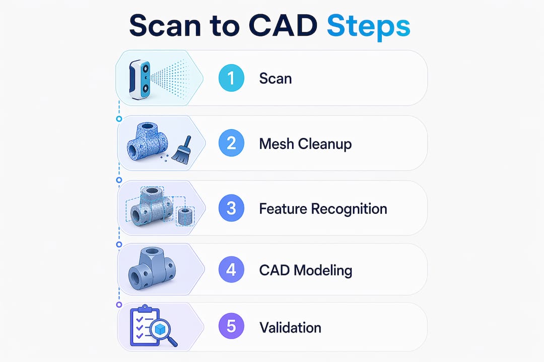
CC 3D Labs offers professional 3D printing services near Philadelphia, with capabilities that include multi-color FDM printing, CAD and design support, and metrology-grade 3D scanning for design accuracy. If your design needs precise dimensional data before printing, scanning an existing part can give you the exact geometry you need to work from. Ready to see what’s achievable? Explore printed prototypes from real projects and get a free online estimate for your next build. Local pickup near Philadelphia or shipping nationwide.

Frequently asked questions

What are the best materials for durable 3D printed project parts?

PETG balances flexibility and strength well for functional assemblies, while PLA offers higher raw tensile strength but is more brittle under repeated flex. ABS delivers 28.5 MPa with better impact toughness, making it the right choice for parts that take hits.

How do you prevent snapped parts or fit failures in snap-fit joints?

Orient your print so the bending stress runs along the layers, not across them, and design cantilever walls 1.5-2.5mm thick in PETG. Printing along layers with PETG reduces delamination and extends the fatigue life of your joints significantly.

Can I design moving parts, like gearboxes, without metal fasteners?

Yes. Bevel and worm gear designs with correct pressure angles and 0.2-0.3mm clearance tolerances allow fully functional gearboxes without any metal hardware, provided your FDM tolerances are dialed in.

What printing settings improve the strength of structural projects?

Use 0.2mm or thinner layers and orient load paths along the print direction. Thinner layers boost strength by 22%, and pairing that with 40%+ infill on structural sections gives you a meaningful improvement over default slicer presets.

Engineer overseeing 3D prototype printing process

How 3D Printing Accelerates Design for Faster Prototyping


TL;DR:

  • Modern 3D printing reduces prototyping costs by up to 90% and speeds lead times from weeks to days.
  • Rapid iteration with 3D printing enables early testing, reduces risks, and improves team communication.
  • Combining in-house and outsourced 3D printing strategies enhances design flexibility and functional quality.

Prototyping has a reputation problem. Most engineers still think of it as the slow, expensive phase where momentum dies and budgets bleed out. But that assumption belongs to a different era. Modern 3D printing has rewritten the math entirely, cutting prototype costs by 50-90% compared to traditional CNC machining and collapsing lead times from weeks down to a matter of days. This article breaks down the real mechanics behind that shift, how to apply it across your workflow, and where most product teams still leave speed and money on the table.

Table of Contents

Key Takeaways

Point Details
Speed up prototyping 3D printing reduces prototype lead times from weeks to days for faster feedback.
Cut iteration costs Switching to 3D printing can slash per-iteration costs by up to 90%.
Choose the right workflow Hybrid workflows leverage both rapid 3D printing and validation with traditional techniques for optimal results.
Validate early and often Regular testing and empirical tolerance checks ensure functional and reliable designs using 3D printing.
Material matters Selecting the correct material and process is essential for turning prototypes into production-ready parts.

How 3D printing transforms the speed of design

Speed in prototyping used to mean cutting corners. With 3D printing, it means eliminating the steps that never added value in the first place.

Traditional manufacturing requires tooling. Before a single part can be made, molds need to be designed, machined, and tested. That process alone can take two to four weeks and cost thousands of dollars before a designer even holds a physical prototype. Then if the design has a flaw, the process starts over. 3D printing removes that entire layer. Once your CAD file is ready, the printer starts. No molds, no setups, no waiting on a machine shop.

The empirical data backs this up clearly. Industry benchmarks show a 63% average lead time reduction from Wohlers Associates, a 70% cut in iteration costs documented by PwC, and Ford Motor Company reporting a 90% reduction in the time needed to produce physical models for new vehicle components. These are not outliers. They reflect what well-integrated 3D printing looks like across industries.

The industries feeling this most sharply include automotive, consumer electronics, medical devices, and aerospace, where rapid design cycles directly determine whether a product reaches market ahead of competition or behind it. Consumer product teams that once needed three weeks per prototype iteration now run through four or five cycles in the same time window.

Below is a quick snapshot of what the before and after looks like for a typical product team:

Metric Traditional process With 3D printing
Prototype lead time 2 to 6 weeks 1 to 5 days
Cost per prototype $2,000 to $10,000+ $50 to $500
Iteration cycles per month 1 to 2 6 to 10
Design change turnaround 2 to 3 weeks Same day to 48 hours
Tooling cost $5,000 to $50,000 None

Key advantages that drive these numbers include:

  • No tooling or setup costs between design changes
  • Files go straight from CAD to build platform
  • Multiple design variants can print simultaneously overnight
  • Complex geometries print without additional cost or machining complexity
  • Short runs and one-off parts are economically viable

If you want a structured look at how this fits into a full product development strategy, the rapid prototyping guide covers the foundational principles in depth. For teams that need parts fast without sacrificing quality, fast turnaround 3D printing is the practical application of these principles. External manufacturing cost-saving methods also show how 3D printing fits into broader efficiency strategies beyond just prototyping.

The design iteration advantage: Rapid cycles and instant feedback

After seeing how the numbers measure up, it is important to understand how this process transforms the workflow of real product development teams, especially when fast, iterative changes are on the line.

The single biggest workflow change 3D printing delivers is not speed. It is the freedom to be wrong earlier and more cheaply. When a prototype costs $8,000 and takes four weeks, teams hedge their bets. They over-engineer designs on paper, delay physical testing, and often discover fundamental flaws only after significant resources are committed. When a prototype costs $80 and takes 24 hours, the psychology shifts completely. Testing becomes routine rather than a milestone.

Consider a typical day in the life of a design team using 3D printing compared to one relying on traditional methods:

  1. Morning design review. The team identifies a clearance issue in the assembly fit from yesterday’s print. A designer opens the CAD file and adjusts the tolerance by 0.3mm.
  2. File prep and submission. The updated file is sliced, reviewed for printability issues, and sent to the printer by 10 AM.
  3. Print runs during the day. The printer runs unattended while the team works on other components or adjacent design problems.
  4. Afternoon evaluation. The new part is ready by mid-afternoon. The team fits it into the assembly, confirms the fix works, and identifies the next issue to address.
  5. Overnight print queued. A further refined version, incorporating all of today’s findings, is queued to run overnight.
  6. Next morning. The team arrives to a finished part and repeats the cycle.

Without 3D printing, step one would trigger a new quote request, a lead time negotiation, and a wait period measured in weeks rather than hours. The cost gap between methods is equally stark: traditional CNC prototyping can cost 5 to 20 times more per iteration, which limits how many cycles a team can run within a fixed budget.

Here is a direct comparison of iteration cycles:

Factor Without 3D printing With 3D printing
Change to physical part 2 to 4 weeks 1 to 48 hours
Cost per iteration $1,000 to $10,000+ $20 to $300
Risk of catching flaws late High Low
Team feedback loops Monthly Daily
Cross-functional testing speed Slow Fast

Pro Tip: Use in-house desktop FDM (Fused Deposition Modeling) or SLA (Stereolithography) printers for rapid, low-risk design iterations on geometry and fit. Reserve outsourced SLS (Selective Laser Sintering) or DMLS (Direct Metal Laser Sintering) for functional prototypes that need near-production material properties. The cost difference is significant and the distinction saves time where it matters most.

For teams who want to build physically reliable parts from the start, designing for reliable 3D prototypes is the right starting point before any iteration cycle begins.

Integrating 3D printing with traditional manufacturing

Now that rapid iteration is clear, the crucial question for engineers is how and when 3D printing best fits into the broader manufacturing toolbox.

3D printing is not a replacement for every manufacturing process. It is a precision tool for specific phases and applications, and misapplying it creates its own set of problems. The teams that get the most value are the ones who know exactly when to use it and when to hand off to traditional methods.

Hybrid strategies represent the most effective approach: use 3D printing for early concepts, design exploration, and complex geometries, then transition to CNC machining or injection molding for validation, durability testing, and production-scale parts. This approach captures speed in the phase where speed matters most, without sacrificing the material strength and tolerances that validated production parts require.

Infographic comparing 3D printing and traditional prototyping steps

Here is a practical breakdown of when to choose each approach:

Use 3D printing when:

  • You need a physical prototype within 24 to 72 hours
  • The geometry is too complex for traditional machining
  • You are running low-volume custom parts (under 100 units)
  • You need to test form, fit, or basic function before committing to tooling
  • Design is still in flux and changes are expected

Use CNC machining or injection molding when:

  • You need tight tolerances under 0.05mm for functional assemblies
  • Parts must withstand high mechanical loads or thermal stress
  • You are producing more than 500 units of the same design
  • Surface finish requirements exceed what FDM or SLA can deliver
  • Material certification is required (aerospace, medical implants)

Pro Tip: Build a deliberate handoff point into your development process. Define upfront which prototype generation marks the transition from 3D printing to traditional manufacturing. Many teams delay this handoff too long, running 3D printed parts through stress tests that expose limitations of the process rather than the design.

Always validate tolerances empirically before assuming a design is production-ready. No simulation and no print specification replaces a physical measurement on a calibrated instrument.

Teams looking to apply these principles at low volume will find low-volume 3D printing tips directly useful, while manufacturing-grade 3D printing covers what it takes to push printed parts closer to production quality. The production optimization guide offers complementary strategies for integrating additive methods across the broader manufacturing pipeline.

Maximizing reliability: Print accuracy, material selection, and quality control

To unlock the full potential of 3D printing within your workflow, reliability and quality must be part of every step, not an afterthought after the print is done.

Material selection is the first decision that determines whether a printed part performs or fails. PLA (Polylactic Acid) is fine for concept models and visual prototypes where loads are minimal. PETG (Polyethylene Terephthalate Glycol) brings better impact resistance and heat tolerance, making it suitable for light functional parts. ASA and ABS handle UV exposure and higher temperatures. For truly functional parts requiring near-engineering-grade properties, Nylon, Polycarbonate, or composite filaments with carbon fiber or glass fill are the right materials. Metal printing via DMLS delivers the closest properties to machined metal, but at a significantly higher cost per part.

Lab specialist handling various 3D print filaments

Accuracy requires attention at the design stage, not just the print stage. Wall thickness, support structures, bridging distances, and orientation all affect dimensional accuracy. A part that looks perfect in CAD can print with 0.5mm of warp if support strategy and material shrinkage are not factored in before slicing.

Empirical validation of tolerances is non-negotiable, particularly for assemblies with mating parts. Prioritize in-house FDM or SLA for iterative design work, and outsource SLS or DMLS when functional prototypes demand tighter tolerances and superior surface quality.

Follow these steps to ensure your printed parts are reliable before scaling up:

  1. Define the functional requirements first. Determine what loads, temperatures, and fits the part must survive before selecting a material or process.
  2. Design for printability. Review wall thickness minimums, avoid unsupported overhangs beyond 45 degrees, and design in clearance where mating parts will interface.
  3. Validate the print setup. Run a test print of a critical feature or cross-section before committing to a full build.
  4. Measure, not just visually inspect. Use calipers or a CMM (Coordinate Measuring Machine) to verify critical dimensions against your CAD model.
  5. Test under real conditions. Fit the part into its assembly, apply representative loads, and confirm behavior before declaring the design ready for the next phase.
  6. Document what worked. Record print settings, material lot, and measured results so you can reproduce the outcome reliably for future builds.

Pro Tip: Never skip design validation before scaling up production quantities. A single print defect that passes visual inspection can become a systematic failure across a batch of 200 parts. Measure first, scale second.

For more on the variables that affect dimensional output, print accuracy for prototyping is a detailed resource on what to control and how.

Why most teams underestimate the true impact of 3D printing

Here is an observation worth sharing directly: most conversations about 3D printing in product development focus on speed and cost savings, as they should. But those are just the most visible benefits. The less obvious and arguably more important impact is what 3D printing does to how teams communicate and make decisions.

When you put a physical prototype on a table during a cross-functional review, something changes. Marketing, manufacturing, QA, and leadership all engage differently with a real object than with a render or a drawing. Feedback becomes concrete. Objections get raised earlier. The kinds of misunderstandings that survive three rounds of 2D documentation rarely survive five minutes with a physical model.

The teams that get the most from 3D printing are not necessarily the ones with the most advanced printers. They are the ones who have built a culture where physical prototyping is routine and expected at every stage of design. They use what their 3D printer can produce not just to test parts but to communicate intent, to challenge assumptions, and to filter out costly mistakes before tooling and capital are on the line.

The conventional framing treats 3D printing as a cost center to be optimized. The more accurate framing treats it as a risk management tool that pays for itself by catching problems at the cheapest possible moment in the development cycle. A $150 print that exposes a fundamental design flaw is worth more than a $15,000 tooling revision that fixes the same problem six months later.

Hybrid approaches, combining desktop FDM or SLA in-house with outsourced SLS or DMLS for functional builds, consistently outperform single-method strategies. But even the best hybrid strategy delivers only part of its potential if the human element is missing. Designer intuition, shop floor experience, and direct stakeholder feedback are not replaced by technology. They are amplified by it.

Accelerate your next design project with expert 3D solutions

Understanding the principles is only the first step. Putting them into practice with the right equipment, materials, and process expertise is where results actually show up.

https://cc3dlabs.com

CC 3D Labs near Philadelphia offers professional 3D printing services built specifically for product developers and engineering teams who need reliable, high-quality results under real project timelines. Whether you need a single concept prototype or a batch of functional parts, the 3D printing on demand service gets your design from file to physical part fast. If you are still scoping what is possible, exploring 3D printing applications shows the full range of what modern filament-based printing can produce for functional, production-grade, and custom needs. Request a free estimate and move your design forward.

Frequently asked questions

How much faster can iterative design cycles be with 3D printing?

Lead times for prototypes can drop from several weeks to as little as 1 to 5 days, enabling up to 63% faster average cycles across the product development process.

Is 3D printing better than CNC machining for all types of parts?

3D printing is the stronger choice for early prototypes and complex geometries, but CNC is preferred for high-strength requirements, tight tolerances, and validated production parts where material properties are critical.

What is the main limitation of using 3D printing in product design?

Material strength and surface finish can lag behind traditional manufacturing, which is why empirical validation of tolerances is essential before any functional prototype moves into production consideration.

Should startups buy a 3D printer or outsource their prototyping?

In-house desktop printers handle rapid, low-cost design iterations well, but outsourcing SLS or DMLS delivers better results for functional, high-precision prototypes that need near-production material performance.