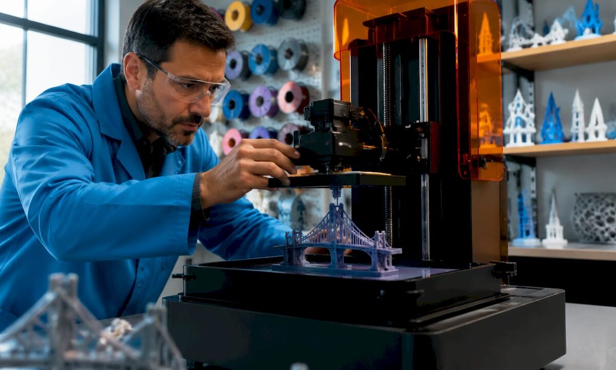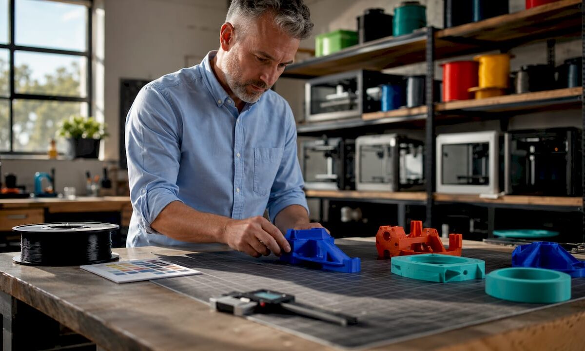
Technician adjusting 3D printer bridging filament

Bridging in 3D Printing: A Practical Guide


TL;DR:

  • Bridging in 3D printing involves extruding filament horizontally between two anchored points without support structures. Proper cooling, speed, and geometry design are essential to produce strong, sag-free spans, with PLA being the ideal filament for bridging due to its fast cooling. Adjusting slicer settings and redesigning parts can reduce reliance on supports and improve print quality across various filament types.

Bridging in 3D printing is defined as the process of extruding filament horizontally between two anchored points without any material beneath to support it. This technique is central to explaining bridging in 3D printing because it determines whether a design needs support structures or can print cleanly on its own. The industry term is “FDM bridging,” and it applies to any filament-based printer using fused deposition modeling. Most well-tuned FDM printers bridge 50–80mm without supports, while optimized setups exceed 100mm. That range tells you exactly how much geometry you can get away with before supports become unavoidable.

How does bridging work in 3d printing?

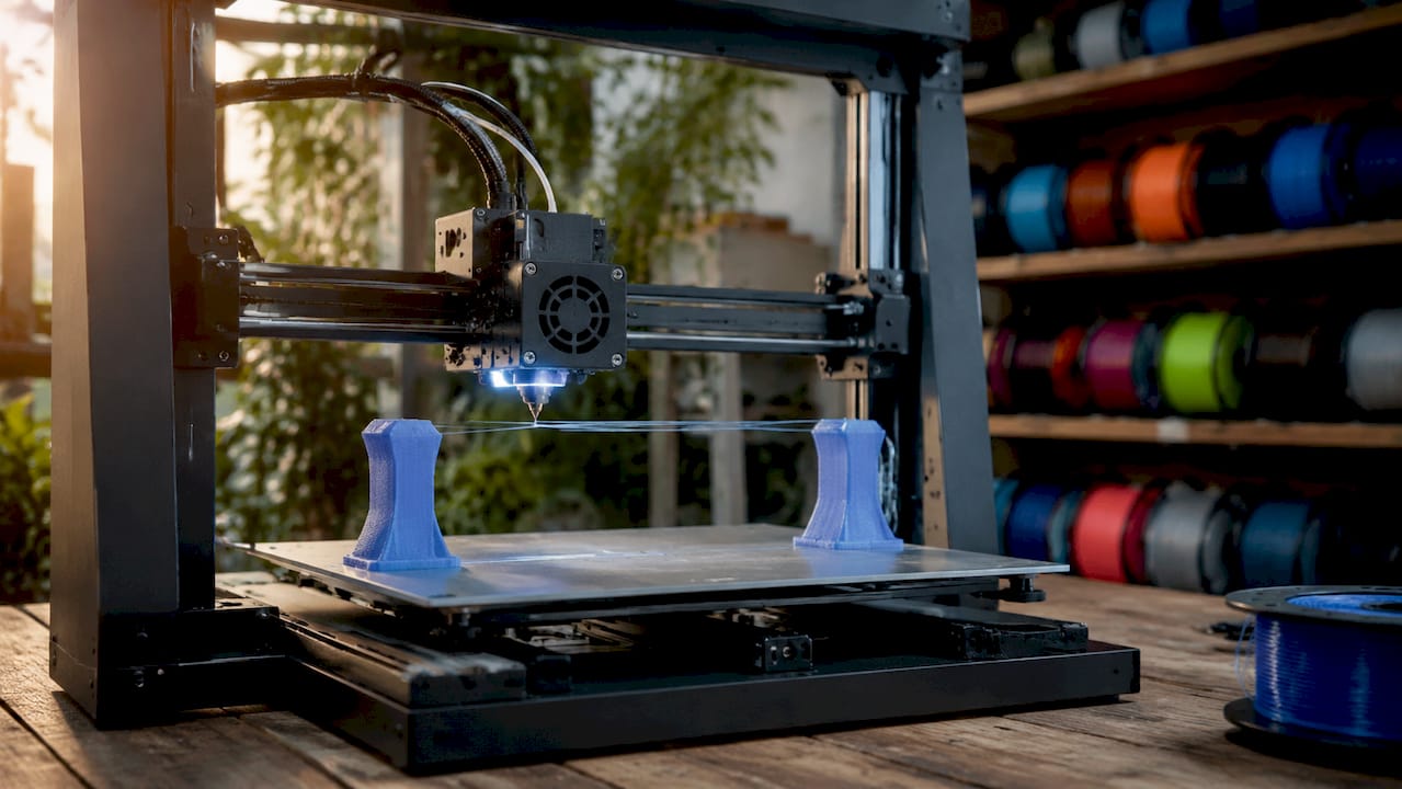
Bridging works by pulling extruded filament taut between two fixed anchor points, much like stringing a wire between two posts. The extruder moves across the gap while depositing molten filament, and the key is that the filament must solidify before gravity pulls it down. Without rapid cooling, the strand sags and ruins the surface below.

Close-up of 3D printer creating filament bridge

Bridging differs from overhangs in one critical way: the filament is anchored at both ends, not just one. An overhang extends outward from a single wall with nothing on the far side. A bridge connects two walls, which gives the extruded strand tension on both ends. That tension is what makes bridging physically possible without support.

The cooling system does the heavy lifting. As the nozzle moves across the gap, the part cooling fan blasts the freshly extruded filament to freeze it in place before it can droop. Speed matters here too. Move too fast and the filament snaps or under-extrudes. Move too slow and the filament stays molten too long and sags under its own weight.

Pro Tip: Run a dedicated bridge calibration test before printing your actual part. Files like the “Bridging Test” models on Printables let you dial in speed and cooling on a throwaway print rather than discovering problems mid-job on a complex prototype.

What slicer settings produce the best bridges?

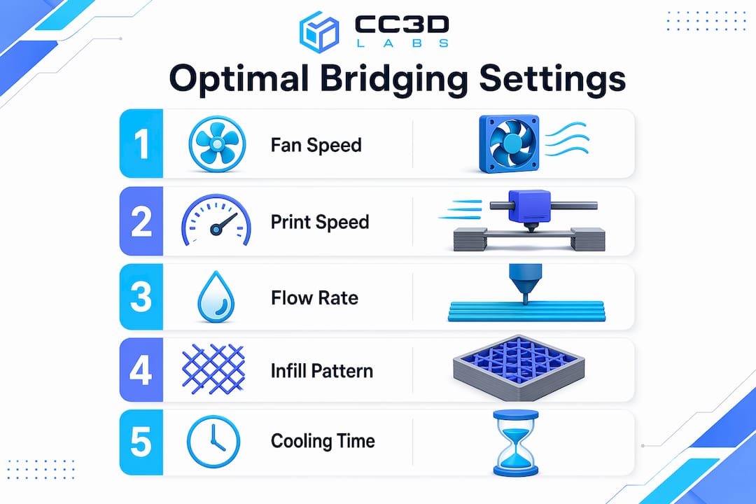
Slicer settings control the outcome of every bridge you print. Getting them right means understanding how cooling, speed, and flow rate interact with each other.

Infographic of key slicer settings for bridging

Cooling

Optimal bridging requires 100% fan speed for most materials. The faster the filament solidifies, the less it sags. ABS and ASA are the major exceptions. Those materials require 30% fan speed or less to prevent thermal warping and layer delamination. Pushing full cooling on ABS will crack the part before the bridge even finishes.

Print Speed

Bridging speed typically falls between 20–80 mm/s depending on the printer and filament. Slower speeds give the cooling fan more time to solidify each strand, which improves surface quality. Faster speeds reduce the time filament stays molten mid-air, which can help with tension. Most users find 30–40 mm/s is the sweet spot for PLA on a well-tuned machine.

Flow Rate and Infill Pattern

Reducing bridge flow to 80–95% prevents excess molten material from building up mid-span. Less material means less weight pulling the strand down. Concentric bridge infill patterns also outperform linear ones because they distribute tension more evenly across the span. Slicers like Simplify3D, PrusaSlicer, and Cura all offer dedicated bridge settings menus where you can override these values independently from the rest of the print.

Pro Tip: Some advanced users push external bridge flow rates up to 140–150% combined with slower speeds. Higher flow rates at lower speeds can improve strand bonding by expanding filament laterally, creating a more uniform surface. Test this on scrap prints first.

What are the most common bridging problems?

Bridge failures follow predictable patterns. Knowing the cause cuts your troubleshooting time in half.

  1. Sagging strands. The most common failure. Caused by insufficient cooling, excessive print temperature, or a span that exceeds the printer’s capability. Drop your print temperature by 5°C and increase fan speed before changing anything else.

  2. Stringing across the gap. Happens when retraction settings are not tuned for bridging. The nozzle oozes material as it travels, leaving thin threads across the span. Increase retraction distance slightly and reduce travel speed.

  3. Drooping at the center. A longer span issue. The filament holds at the anchors but sags in the middle. Shorten the span through part redesign, or split the bridge into two shorter sections with a mid-span support column.

  4. Inconsistent extrusion. The bridge looks uneven or has gaps. Hardware issues like clogged nozzles or wet filament produce extrusion inconsistencies that mimic slicer setting errors. Dry your filament and clean the nozzle before adjusting any parameters.

  5. Warping at bridge edges. Common with ABS and ASA. The rapid temperature change at the bridge edges causes the corners to lift. Reduce cooling, increase bed temperature, and consider an enclosure.

Pro Tip: Bridge failures often signal cooling or geometry issues rather than a simple settings error. Always check hardware first. A partially clogged nozzle will make every bridge look like a settings problem when the real fix is a cold pull.

How does filament type affect bridging?

Every filament behaves differently mid-air. Matching your settings to your material is non-negotiable for consistent results.

  • PLA is the best material for bridging. It cools fast, holds tension well, and tolerates 100% fan speed without warping. Most bridging benchmarks and tutorials use PLA as the baseline. If you are learning to tune bridges, start here.

  • ABS and ASA require a fundamentally different approach. Full cooling causes warping and layer separation. Keep fan speed at 30% or below, slow the bridge speed to 20–25 mm/s, and use an enclosure to maintain ambient temperature. Bridging spans with ABS should be kept shorter than with PLA. For a deeper look at how these materials compare, the PLA vs. PETG vs. ABS guide from Cc3dlabs covers mechanical trade-offs in detail.

  • PETG sits between PLA and ABS in bridging difficulty. It strings aggressively and stays tacky longer than PLA, which causes strands to sag and stick to each other. Reduce flow to 80%, increase retraction, and run fan speed at 50–70%. Expect more post-processing cleanup on PETG bridges.

  • Flexible filaments like TPU are nearly impossible to bridge cleanly. The material stretches under tension instead of holding taut. For flexible parts with horizontal spans, support structures are the only reliable option.

The pattern across all materials is the same: faster cooling and lower flow rates improve bridge quality, but each material has a ceiling on how much cooling it can tolerate before other problems appear.

Design strategies that reduce bridging problems

Smart geometry eliminates many bridging problems before the print even starts. The table below compares common design approaches and their trade-offs.

Strategy Best For Trade-Off
Add chamfers at 45° Replacing flat bridges with angled surfaces Slightly changes part geometry
Split bridge into segments Long spans over 60mm Requires mid-span support columns
Reorient the part Shortening bridge direction May increase total print height
Reduce span width in CAD All bridging scenarios Requires design iteration
Use a teardrop hole shape Circular holes on vertical faces Changes hole aesthetics

Part redesign to reduce bridge span is the preferred approach in batch production because it eliminates post-processing labor and reduces failure rates at scale. Adding a 45° chamfer to the underside of a horizontal feature converts a flat bridge into a series of short overhangs, which most printers handle without any special settings. For production-focused design decisions, the 3D part optimization guide from Cc3dlabs walks through geometry choices that reduce support dependency across entire part families.

Reorienting the part on the build plate is often the fastest fix. A span that runs 80mm in one orientation might only run 30mm when the part is rotated 90°. That single change can move a print from “needs supports” to “prints clean” with zero CAD edits. For low-volume production runs, the low-volume manufacturing guide covers when orientation changes deliver the most value.

Key takeaways

Successful bridging in FDM printing depends on matching cooling, speed, and flow rate to your specific material, then designing geometry that keeps spans within your printer’s capability.

Point Details
Standard bridging span Most FDM printers handle 50–80mm cleanly; optimized setups exceed 100mm.
Cooling is the primary lever Run 100% fan speed for PLA; limit ABS and ASA to 30% or less to prevent warping.
Flow rate matters Set bridge flow to 80–95% to reduce mid-span sag and excess material buildup.
Check hardware before settings Clogged nozzles and wet filament mimic slicer errors; fix hardware first.
Design beats troubleshooting Chamfers, part reorientation, and shorter spans outperform support structures in production.

What i’ve learned after years of watching bridges fail

The most common mistake I see is treating bridging as a pure settings problem. Someone gets a saggy bridge, opens their slicer, and starts adjusting fan speed and flow rate for an hour. Then they discover the filament spool has been sitting open for three weeks and absorbed moisture. Wet filament produces inconsistent extrusion that no slicer setting can fix. Dry your filament first. Clean your nozzle. Then tune settings.

The second thing I’ve changed my mind on is supports. Early in my experience, I added supports liberally because they felt like a safety net. Now I treat them as a last resort. Every support structure adds post-processing time, leaves surface marks, and increases material cost. A well-placed chamfer or a 10-minute CAD edit almost always beats an hour of support removal and surface cleanup. For anyone running batch production, that math compounds fast.

The emerging trend worth watching is higher bridge flow rates. Pushing flow to 140–150% combined with slower speeds is counterintuitive, but the logic holds. Wider strands bond to each other more effectively, creating a more solid surface. I’ve tested this on PLA with good results, though it requires careful calibration to avoid over-extrusion at the anchor points. It is not a setting to deploy without testing, but it is worth experimenting with on complex geometries.

My overall advice: be methodical. Change one variable at a time, run a calibration print, and document what you observe. Bridging is solvable for almost any geometry if you approach it systematically rather than randomly adjusting sliders.

— Justin

Get professional help with complex print geometry

When bridging challenges are holding back your prototype or production timeline, Cc3dlabs has the equipment and expertise to handle it.

https://cc3dlabs.com

Cc3dlabs, based near Philadelphia, specializes in custom filament-based 3D printing for prototypes, functional parts, and batch orders. The team tunes print parameters for each job, including bridge-specific settings, cooling profiles, and part orientation, so you get clean results without the trial-and-error cycle. Whether you need a single prototype or a production run with complex geometry, Cc3dlabs offers free online estimates, design support, and fast turnaround. Reach out to discuss your project and get a print that performs.

FAQ

What is bridging in 3d printing?

Bridging is the process of extruding filament horizontally between two anchored points without support material beneath. It is a standard FDM technique used to print horizontal spans cleanly without adding support structures.

How long of a bridge can a 3d printer handle?

Most well-tuned FDM printers handle spans of 50–80mm without supports. Optimized machines with dialed-in cooling and speed settings can exceed 100mm.

What is the best filament for bridging?

PLA is the best filament for bridging because it cools fast, holds tension well, and tolerates 100% fan speed. ABS, ASA, and PETG require lower cooling and more careful tuning.

Why does my bridge keep sagging?

Sagging is most often caused by insufficient cooling, excessive print temperature, or a span that exceeds your printer’s capability. Check for wet filament or a clogged nozzle before adjusting slicer settings.

Should i use supports instead of bridging?

Supports should be reserved for genuine geometry challenges after you have optimized cooling, speed, and part orientation. Redesigning the part with chamfers or shorter spans almost always produces better results than adding supports.

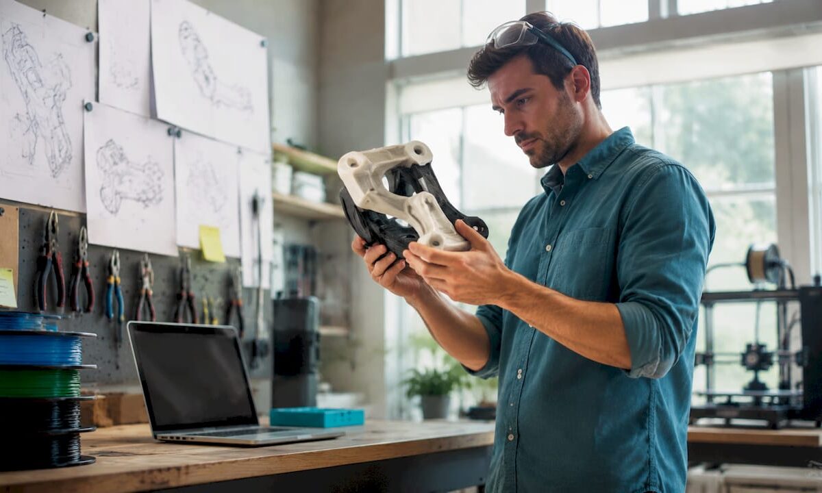
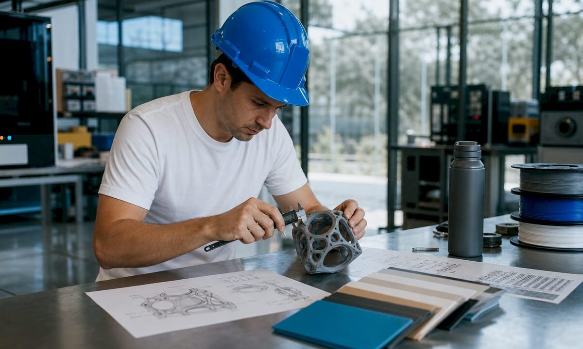
Engineer inspecting 3D printed prototype in lab

Top 3 print3dllc.net Alternatives Providers 2026

Selecting a three-dimensional printing and scanning service for anything from prototypes to industrial parts leads to delays and unclear pricing more often than not. Many competitors only list vague quote forms, restrict material choices, or focus solely on printing without scanning support. This comparison matches providers to your needs for precise parts, fast turnarounds, and transparency in materials or price structure so you can choose confidently.

Table of contents

CC 3d labs

https://cc3dlabs.com

At a glance

Metrology grade 3D scanning operates alongside filament based production at CC 3D Labs’ Philadelphia workshop. The shop produces prototypes, functional parts, and small batch runs using engineering grade materials and multi material color printing. Clients can request free online estimates and choose local pickup or shipping.

Core features

  • Custom 3D printing for prototypes and functional parts using filament based processes. This covers parts intended for testing and real use.
  • Multi material and multi color 3D printing for models that need distinct materials or visual fidelity. Useful for assemblies and presentation models.
  • On demand manufacturing and batch production for short runs and small series. The service supports production scaling from single parts to batches.
  • 3D scanning and reverse engineering with metrology grade scanning. This supports repair, calibration, and accurate digital capture of physical parts.
  • Engineering grade materials selected for impact, heat, and wear resistance. Options target functional end use and mechanical testing.

Key differentiator

Multi material and multi color printing plus engineering grade materials let CC 3D Labs focus on functional, real world parts made quickly. The combination of detailed filament based printing and metrology grade scanning supports tight tolerances and matched repairs. That mix is uncommon for small local shops that also accept batch orders. The result is a practical bridge from prototype to short run production for designers and engineers.

Pros

  • High print quality and dimensional accuracy. The shop emphasizes precision that matters for functional testing and assembly.

  • Fast local turnaround for Philadelphia area clients. Local pickup reduces shipping time for urgent prototypes.

  • Broad material selection including specialty engineering filaments. That lets you pick materials for heat, wear, or impact resistance.

  • Multi material and multi color capabilities for complex assemblies or presentation pieces. You can show stakeholders realistic prototypes without painting.

  • Complementary services such as scanning, repair, calibration, and design support. That reduces the number of vendors you must coordinate for product development.

Cons

  • Coverage for some on site services is limited to specific areas, though the company ships worldwide.

Who it’s for

Manufacturers, product designers, engineers, small production teams, and hobbyists who need precise, durable parts and scanning near Philadelphia will find this service useful. Remote clients who require shipping can also use the lab for parts and scans. The service suits projects that need material choices and realistic multi color prototypes.

Unique value proposition

Free online estimates and local pickup shorten procurement for Philadelphia teams. That lowers the friction of ordering prototypes while preserving access to engineering grade materials and detailed scans. For product developers this reduces the calendar time between design iteration and physical testing. The combination of quoting, local pickup, and shipping makes procurement flexible for local and remote projects.

Real world use case

A Philadelphia startup orders multi material prototypes for a consumer electronics enclosure. The lab scans legacy parts, prints functional prototypes in engineering grade filament, and delivers parts for investor demos. The physical prototypes then move into testing before the startup selects a vendor for large scale tooling.

Pricing

Pricing is provided by quote rather than fixed tiers. The website and staff supply free online estimates so clients can compare material and production options before committing. For accurate costs you must submit part files and production details to receive a tailored quote.

Website: https://cc3dlabs.com

Philadelphia precision CNC

https://philadelphiacnc.com

At a glance

Waterjet cutting for high precision sheet metal work operates alongside CNC routing, laser, plasma, and 3D scanning under one roof. The shop handles both medium to large projects and smaller runs for artists and makers. Turnarounds are positioned as fast, with design support and material sourcing available.

Core features

  • CNC routing and engraving for wood, plastic, foam, and other common fabrication materials. Works for signage, molds, and detailed panels.

  • 3D scanning and digital recreation to capture shapes and reproduce or modify complex surfaces. Useful for restorations and reverse engineering.

  • Waterjet cutting for high precision cuts in sheet metal and other hard materials. Good where heat from other tools would damage the part.

  • Laser and plasma cutting for thick or high-tolerance parts. Suited to architectural pieces and metal fabrications.

  • Fabrication and installation services including prototype assembly and on or off site build outs. The shop offers project management support.

Key differentiator

Philadelphia Precision CNC combines multiple high-precision cutting methods with on-site 3D scanning and fabrication. That mix lets a single vendor take a part from scanned model to finished, installed piece. The setup benefits clients who want fewer handoffs between scanning, cutting, and assembly. It therefore favors clients with complex fabrication workflows rather than simple one-off cuts.

Pros

  • Offers a wide set of cutting technologies and scanning in one shop. That reduces coordination between vendors and keeps technical knowledge in a single team.

  • Fast turnarounds for medium to large projects are a stated focus. For builders and contractors, that reduces schedule risk on staged work.

  • Design consultation and material sourcing come with project support. Clients who lack a preferred supplier can tap the shops contacts.

  • Serves architects, contractors, artists, and makers with cross-discipline experience. This helps when a project mixes aesthetics and structural demands.

  • Established team with machining and fabrication expertise. That background helps with unusual materials or tight tolerances.

Cons

  • The website provides limited information on pricing and specific lead times. You will likely need to request a quote for any meaningful estimate.

  • There are no clear details about the specific CAD or CAM tools used. That can complicate file prep if you need a particular file format.

  • Public pages lack customer reviews or detailed case studies. That makes it harder to verify performance on projects similar to yours.

When it may not fit

If you need instant online quoting or transparent price lists, this provider will not match that expectation. Clients that rely on a specified CAD toolchain or automated file checks may face extra back-and-forth. If you require a fully documented gallery of past client outcomes before engaging, the site does not supply that level of detail.

Who it’s for

Designers, builders, and makers in the Philadelphia region who need precise cutting combined with scanning and fabrication. Contractors with staged installations will benefit from the shops assembly and project management support. Artists or architects who work with mixed materials and need a single vendor for complex builds will find value here.

Real world use case

A local artist needs custom cut acrylic panels and metal mounting plates for an installation with tight fit tolerances. The shop scans the mockup, programs CNC and laser files, cuts the parts, and assembles the mounts for site installation. The single-vendor workflow reduced scheduling friction and saved a round of vendor handoffs.

Pricing

Pricing is not listed on the public site and is described as informational only. Expect custom quotes based on material, cutting method, part complexity, and installation needs. Contacting the shop for a written estimate is required to get a firm price.

Website: https://philadelphiacnc.com

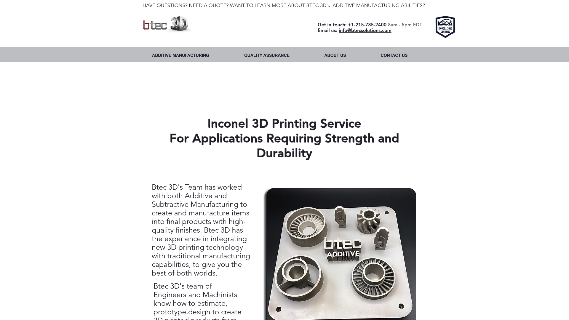
Inconel 3d printing service by btec 3d

https://btec3d.com

At a glance

Btec 3D pairs metal powder additive techniques with subtractive finishing to deliver finished Inconel components from design to delivery. The team operates from Croydon, PA, and focuses on industrial tooling and final parts for demanding sectors like aerospace and automotive. Their workflow emphasizes engineering support, quality assurance, and final-part readiness.

Core features

Btec 3D handles metal powder based 3D printing for high strength applications and follows with machining as needed for tight tolerances. The service includes design, prototyping, and estimating steps so you can validate parts before moving to production. Full quality assurance is part of the process, and the team delivers parts with high quality finishes suitable for functional use. The offering targets small batch production and one off custom tooling for industrial customers.

Key differentiator

The standout capability is the combination of additive and subtractive manufacturing inside a single production workflow. That approach lets Btec 3D print near net shapes in Inconel and then machine critical surfaces to meet tolerance and finish requirements. For projects that need both material performance and machined accuracy this reduces handoffs and aligns engineering with final production.

Pros

  • Specialized for Inconel applications. The team focuses on high strength metal work relevant to aerospace and automotive needs.
  • Combines printing with machining. This reduces coordination between vendors and shortens the iteration loop for tight tolerance parts.
  • Engineering and prototyping support. Btec 3D offers design and estimating help so you can move prototypes toward production with fewer surprises.
  • Full quality assurance and production finishing. The service produces parts that are ready for functional use rather than just printed test pieces.
  • Local production in Croydon, PA. Local pickup and closer project oversight are available for nearby manufacturers.

Cons

  • Pricing and specific lead time details are not publicly listed in the provided materials, which makes budgeting harder up front.
  • The offering concentrates on metal parts, primarily Inconel, so it does not serve non metal prototyping needs.
  • The provided data lacks clarity on the broader material portfolio, so if you need alternate alloys you will need to confirm availability directly.

When it may not fit

If your project requires rapid prototyping in plastics or composite materials this service is the wrong fit. If you need transparent online pricing for quick vendor comparison the limited public pricing information will slow procurement. For large volume metal runs you should confirm capacity and lead times with Btec 3D before committing.

Who it’s for

Manufacturers and engineers who need durable, high strength metal components with machined tolerances will get the most value. The service suits aerospace and automotive teams, tooling shops, and product developers needing finished Inconel parts rather than raw printed blanks. It also fits buyers who prefer a single vendor for print and machine steps.

Real world use case

An aerospace supplier worked with Btec 3D to produce Inconel fuel system parts. The supplier used Btec 3D for design review, printed near net shapes, and then had critical sealing surfaces machined to print drawing tolerances. The result was delivery of ready to install components with documented quality checks.

Pricing

Pricing is not specified in the available product information. Expect custom quotes based on part geometry, material use, post processing, and batch size. Contact Btec 3D for an estimate and lead time for your specific application.

Website: https://btec3d.com

Comparison of alternatives

When considering top-tier three-dimensional printing and scanning services, understanding the strengths of each provider informs choice. Let’s examine the offerings of CC 3D Labs, Philadelphia Precision CNC, and Inconel 3D Printing Service by Btec 3D to illuminate their distinctive advantages.

Flexibility in material offerings

CC 3D Labs specializes in filament-based, multi-material capabilities suitable for prototypes and functional parts. This supports diverse material needs by offering engineering-grade options. In contrast, Btec 3D excels in Inconel metal production augmented by precision machining, ideal for high-strength applications in aerospace sectors where robustness under extreme conditions is.

Workflow and project scope alignment

Philadelphia Precision CNC provides a workflow accommodating scanning, cutting, and assembly stages, allowing smooth management of complex projects. This is ideal for clients pursuing intricate fabrication tasks or artistic installations requiring integrated solutions. CC 3D Labs, while excelling in scanning and localized production, may not offer this full-spectrum fabrication service.

Best fit

  • Projects requiring high-resolution, multi-material prototyping, and engineering-grade materials will benefit from CC 3D Labs’ tailored capabilities.
  • Clients needing high-strength metal parts, particularly in demanding applications like aerospace or automotive, will find Btec 3D an excellent choice.
  • For creative endeavors or projects necessitating integrated design and installation workflows, Philadelphia Precision CNC presents a powerful option.

Our pick

CC 3D Labs stands out for its emphasis on precise engineering material application combined with advanced scanning technology. This makes it particularly well-suited for users seeking responsive, high-accuracy prototyping services and short-run production. However, if metal-based production or fabrication workflows are prioritized, selecting an alternative provider may better align with your needs.

To identify the best service provider for three-dimensional printing and scanning needs, the following table highlights and compares top alternatives based on core features and distinguishing elements.

Provider Core Offering Key Differentiator Best For Pricing
Cc3dlabs Prototyping, multi-material printing, and metrology scanning Combines detailed printing with engineering-grade output Local and remote clients needing durable prototypes Not disclosed
Philadelphia Precision CNC CNC routing, waterjet cutting, scanning, and fabrication Integrates scanning and fabricating within one workflow Builders and designers with complex fabrication needs Not disclosed
Btec 3D Inconel 3D printing with machining Blends additive and subtractive processes for final parts Aerospace manufacturers requiring high-strength components Not disclosed

Discover a reliable print3dllc.net alternative with Cc3dlabs

If you are searching for dependable, high precision 3D printing services that go beyond basic production, Cc3dlabs offers a trusted alternative to print3dllc.net. This Philadelphia-based provider specializes in engineering grade filament prints, multi-color capabilities, and metrology-grade 3D scanning—ideal for functional prototypes and small batch production. Their flexible options, including free online estimates and local pickup, target the key pain points of rapid turnaround, accuracy, and material variety.

https://cc3dlabs.com

Explore how Cc3dlabs can support your most demanding projects by visiting Cc3dlabs. Request a free quote today and experience precise, durable parts delivered with speed and expertise tailored just for your development needs.

FAQ

How does Cc3dlabs support multi material and multi color printing for prototypes?

Cc3dlabs offers multi material and multi color 3D printing that allows for detailed assemblies and presentation models. This capability supports realistic prototypes without requiring additional finishing work. If you’re seeking to create complex models that stand out, Cc3dlabs will meet your needs effectively.

What is the difference between Cc3dlabs and philadelphia precision CNC in terms of services?

Philadelphia Precision CNC excels in offering a wider variety of cutting methods like waterjet and CNC routing, beneficial for large, complex industrial projects. In contrast, Cc3dlabs specializes in custom 3D printing and scanning, making it a better fit for those needing rapid prototyping of functional parts. Choose Cc3dlabs for precise, durable prototypes that require engineering grade materials.

Can i rely on Cc3dlabs for engineering grade materials?

Cc3dlabs utilizes engineering grade materials that provide impact, heat, and wear resistance, targeting functional end use and mechanical testing. This focus on quality ensures that your prototypes can withstand real-world applications. If you’re developing parts that need to endure, Cc3dlabs is the right choice.

How does Cc3dlabs’ quotation process work?

Cc3dlabs provides free online estimates for clients wanting to compare material and production options before making a decision. By submitting part files and production details, you receive a tailored quote, allowing for informed budgeting. This makes it easy to kickstart your project without upfront commitments.

What advantages does Cc3dlabs offer for local clients in philadelphia?

Cc3dlabs ensures fast local turnaround for clients in the Philadelphia area, enabling local pickup which greatly reduces shipping time for urgent prototypes. This local focus allows for quicker access to engineering services and materials, making it the ideal option for time-sensitive projects.

Engineer working on 3D drafting model at drafting table

Drafting Standards in 3D Modeling: Engineer’s Guide


TL;DR:

  • Drafting standards in 3D modeling establish rules for communicating design intent, geometry, and tolerances across workflows. They enable precise, unambiguous data exchange and prevent costly manufacturing errors by ensuring models are inspection-ready and organized properly. Enforcing these standards through software tools and workflow integration is essential for reliable, production-ready 3D models.

Drafting standards in 3D modeling are defined rule sets that govern how design intent is communicated, measured, and verified across every stage of a production workflow. These standards cover geometric dimensioning and tolerancing (GD&T), CAD data organization, and interoperability protocols. The two most referenced frameworks are ASME Y14.5, which defines symbolic tolerancing language for manufacturing, and ISO 10303 (STEP), which governs cross-platform data exchange. Without these standards, a model that looks correct on screen can produce parts that fail inspection on the shop floor.

What are drafting standards in 3d modeling?

Drafting standards in 3D modeling are the formal rules that define how geometry, dimensions, tolerances, and annotations are structured inside a CAD file. The industry term for this discipline is model-based definition (MBD), and it represents a shift away from 2D drawing packages toward fully annotated 3D models. CAD standards cover both appearance conventions such as layers, dimension styles, and symbols, and data organization rules that determine how files are named, structured, and exported.

Hands examining 3D modeling drafting standards documents

A common misconception is that these rules are primarily about visual consistency. The real value lies in precise, unambiguous communication of size, shape, and tolerances that enables reliable manufacture and inspection. When a machinist or a coordinate measuring machine (CMM) reads a model, every symbol must carry exactly one interpretation. Ambiguity at this stage translates directly into scrap, rework, and cost overruns.

For 3D designers and engineers, understanding drafting standards means recognizing two parallel layers of rules. The first layer is semantic: GD&T symbols, datum references, and tolerance callouts. The second layer is structural: file naming, layer organization, metadata, and export format. Both layers must be correct for a model to move cleanly through a CAD modeling workflow.

Gd&t, data structure, and annotations explained

Geometric dimensioning and tolerancing (gd&t)

GD&T is the symbolic language that turns design intent into quantifiable requirements. ASME Y14.5 is the dominant standard in North America, and it defines symbols for flatness, cylindricity, true position, runout, and more than a dozen other geometric characteristics. Each symbol attaches a specific, measurable meaning to a feature. That specificity is what allows a CMM to verify a part automatically without a human interpreter.

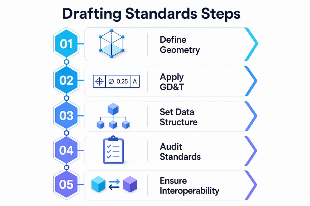
Infographic illustrating key steps in drafting standards process

MBD workflows embed these GD&T annotations directly into the 3D model as Product Manufacturing Information (PMI). Embedding PMI in 3D models enables CAD, PLM, CAM, and metrology systems to read design intent identically without intermediate translation. This eliminates the version-control problem that plagues organizations still maintaining parallel 2D drawing sets.

Pro Tip: When setting up PMI in software like Siemens NX or PTC Creo, attach every tolerance to a named datum reference frame from the start. Retrofitting datum structure onto a finished model costs far more time than building it correctly upfront.

CAD data structure and naming conventions

Data structure rules govern how a model is organized inside the file and across a project directory. Standard conventions include layer naming schemas, block or component naming, line weight assignments, and metadata fields like revision number and material specification. The National CAD Standard (NCS) and ISO standards both provide frameworks for these conventions, improving consistency and enabling data exchange between organizations.

Poorly organized CAD data passes visual checks but fails downstream. A model with correct geometry but misnamed layers or missing metadata will break automated manufacturing and inspection pipelines. Splitting standards into semantic rules (GD&T) and data-structure rules prevents this failure mode.

How CAD software enforces drafting standards

CAD platforms provide built-in tools to apply and audit drafting guidelines for 3D workflows. The enforcement mechanism matters as much as the standard itself. A style guide that lives in a PDF and is never checked produces inconsistent results across a team.

Autodesk AutoCAD uses standards files with the .DWS extension to enforce layer names, text styles, dimension styles, and line type properties. CAD standards auditing checks active drawings against these files and flags or automatically corrects any deviation. This workflow prevents standards drift in multi-user environments where individual designers make local modifications over time.

Here is how a typical CAD standards enforcement workflow runs in AutoCAD:

  1. A standards administrator creates a .DWS file that defines approved layers, styles, and properties for the project.
  2. The .DWS file is distributed to all team members and linked to active drawing files.
  3. Designers run the CHECKSTANDARDS command to audit their work before submission.
  4. AutoCAD flags non-conforming elements and offers automatic fixes where the correction is unambiguous.
  5. A project lead reviews the audit report and approves the file for release.

Pro Tip: Schedule automated standards checks as part of your file-save routine using AutoCAD’s notification settings. Catching a layer naming error at save time takes seconds. Catching it after a file has been handed to manufacturing takes hours.

The real power of drafting standards comes from enforceability through software auditing and team discipline, not from style guides alone. Organizations that rely on documentation without automated checks consistently produce non-conforming files.

Why interoperability standards matter for 3d collaboration

ISO 10303 (STEP) and cross-platform data exchange

ISO 10303, universally known as STEP, is the international standard for exchanging product model data across CAD, CAM, CAE, and PDM systems. STEP subdivides into approximately 700 standards and supports long-term archival as well as system-independent 3D model exchange. That breadth makes it the default format for aerospace, automotive, and defense supply chains where multiple organizations use different CAD platforms.

STEP preserves both geometry and topology, but semantic data preservation requires additional care. A model exported from CATIA and imported into SolidWorks may retain its surfaces while losing PMI annotations if the application protocol (AP) does not support that data scope. Interoperability depends on exporter and importer behavior and must be verified at each step in the toolchain.

Comparing key interoperability standards

Standard Primary Use Data Preserved Industry Focus
ISO 10303 (STEP) Cross-platform CAD exchange Geometry, topology, PMI (AP-dependent) Aerospace, automotive, defense
IFC (ISO 16739) Building and infrastructure models Geometry, spatial relationships, metadata Architecture, engineering, construction
IGES Legacy geometry exchange Geometry only General manufacturing (legacy)
OBJ / FBX Visualization and rendering Geometry, color, UV maps Media, gaming, visualization

For architecture, engineering, and construction (AEC) workflows, IFC (Industry Foundation Classes) fills the same role that STEP fills in mechanical engineering. IFC carries spatial relationships, component metadata, and building system data that STEP does not address. Choosing the wrong format for your industry means losing the semantic layer that makes a model useful beyond simple geometry.

Validating standards compliance at every handoff point is non-negotiable. Run format validation tools before sending files to partners or manufacturers. A translation error discovered after a part is machined is far more expensive than one caught during file review. For a practical look at CAD file format selection, the format choice directly affects how much of your standards-compliant data survives the transfer.

Best practices for production-ready 3d models

Drafting standards address how design intent is communicated. Production modeling standards address whether the geometry itself is manufacturable and pipeline-ready. Both sets of rules must be satisfied for a model to move from design to physical output without rework.

Professional 3D modeling standards emphasize clean topology, polygon efficiency, consistent edge flow, proper UV unwrapping, and the elimination of non-manifold geometry. These requirements apply whether the output is a rendered animation, a CNC toolpath, or a 3D print. Non-manifold geometry, for example, causes slicer software to fail silently, producing prints with missing walls or internal voids.

A production-ready model checklist covers the following areas:

  • Topology: Use quads as the primary polygon type. Triangles are acceptable at termination points. N-gons cause shading artifacts and should be resolved before export.
  • Scale and units: Set the correct real-world scale before modeling begins. A part modeled at the wrong unit system will print at the wrong size even if the geometry is perfect.
  • Naming conventions: Name every component, material, and UV channel descriptively. Generic names like “Mesh001” create confusion in assembly files and pipeline handoffs.
  • Non-manifold geometry: Run a manifold check in tools like Meshmixer, Netfabb, or the slicer’s built-in repair function before finalizing any model intended for physical production.
  • File organization: Group components logically, purge unused assets, and save in the format required by the downstream tool.
Quality Check Tool Pass Criteria
Manifold geometry Meshmixer, Netfabb Zero open edges or non-manifold faces
Scale verification CAD software ruler Matches engineering drawing dimensions
Naming convention Manual review or script All objects follow project naming schema
PMI completeness CAD PMI manager All features have tolerance callouts

These production standards integrate directly with drafting standards. A model with correct GD&T annotations but broken topology will still fail at the manufacturing stage. End-to-end quality assurance requires both layers to be correct. For engineers focused on tolerances in 3D printing, the connection between GD&T callouts and physical print accuracy is direct and measurable.

Key takeaways

Drafting standards in 3D modeling require both semantic precision (GD&T and PMI) and structural discipline (data organization and interoperability) to produce models that are reliable from design through manufacturing.

Point Details
GD&T is the core semantic layer ASME Y14.5 symbols turn design intent into machine-readable, verifiable requirements.
MBD replaces 2D drawings Embedding PMI directly in 3D models eliminates ambiguity and version-control problems.
Software enforcement is mandatory AutoCAD .DWS auditing and similar tools prevent standards drift across multi-user teams.
STEP governs data exchange ISO 10303 preserves geometry and PMI across platforms, but AP compliance must be validated.
Production standards complete the picture Clean topology, correct scale, and organized assets are required alongside drafting rules for production-ready output.

Where standards break down in real projects

Most standards failures I see at Cc3dlabs do not come from ignorance of ASME Y14.5 or ISO 10303. They come from the gap between knowing a standard and enforcing it consistently across a team under deadline pressure. A designer who understands GD&T perfectly will still skip datum references when a project is running late. That shortcut costs far more time downstream than it saved upfront.

The shift toward MBD is real and accelerating, but it creates a new failure mode. Teams that move tolerances and annotations from 2D drawings into 3D PMI sometimes assume the software handles validation automatically. It does not. PMI that is geometrically attached but semantically incomplete passes visual inspection and fails CMM verification. I have seen this exact problem delay production runs by days.

My practical recommendation is to treat standards enforcement as a workflow step, not a final review. Build .DWS checks, manifold validation, and PMI completeness reviews into the save and submit process. Make them automatic and non-optional. The teams that do this consistently produce fewer non-conforming files and spend less time on rework. The teams that treat standards as a checklist item at the end of a project spend a disproportionate amount of time fixing problems that were created weeks earlier.

The future of 3D design drafting rules points toward tighter integration between CAD, 3D printing, and metrology. As CAD integration drives printing precision, the standards embedded in your model become the direct input to both the printer and the inspection system. Getting those standards right is not a documentation exercise. It is the foundation of a reliable production process.

— Justin

How Cc3dlabs supports standards-compliant 3d production

When your model meets drafting and production standards, the path from file to finished part is fast and predictable. Cc3dlabs works with engineers and product developers near Philadelphia and worldwide to turn standards-compliant CAD files into precise, functional parts. The team reviews incoming models for production readiness, flags geometry issues before printing begins, and delivers parts that match the tolerances specified in your design.

https://cc3dlabs.com

Whether you need a single prototype or a batch production run, Cc3dlabs’ 3D printing services are built around the same quality standards covered in this guide. From filament-based FDM parts to metrology-grade 3D scanning, every project starts with a free online estimate and direct design support. Submit your file and get a quote today.

FAQ

What are drafting standards in 3d modeling?

Drafting standards in 3D modeling are formal rule sets that govern how geometry, dimensions, tolerances, and annotations are structured in a CAD file. They include GD&T frameworks like ASME Y14.5 and data organization conventions that ensure models are clear, consistent, and production-ready.

What is gd&t and why does it matter for 3d models?

GD&T (Geometric Dimensioning and Tolerancing) is a symbolic language defined by ASME Y14.5 that communicates exact size, shape, and tolerance requirements for manufactured parts. It matters because it replaces ambiguous notes with machine-readable symbols that CMMs and CAM software can interpret without human interpretation.

What is the difference between STEP and IGES for CAD data exchange?

STEP (ISO 10303) preserves geometry, topology, and PMI annotations depending on the application protocol used, making it the current standard for cross-platform exchange. IGES is a legacy format that transfers geometry only and lacks support for semantic data like tolerances and metadata.

How does model-based definition (MBD) change drafting workflows?

MBD embeds GD&T annotations and PMI directly into the 3D model, eliminating the need for separate 2D drawing packages. This reduces ambiguity and allows CAD, CAM, and metrology systems to read design intent from a single source of truth.

What tools enforce CAD drafting standards across a team?

AutoCAD uses .DWS standards files to audit layer names, text styles, and dimension properties against approved project standards. Running the CHECKSTANDARDS command flags and corrects non-conforming elements before files are released to manufacturing or shared with collaborators.

Artist sketching custom wedding 3D print design

Custom Wedding 3D Prints: 10 Inspiring Examples


TL;DR:

  • Custom wedding 3D prints offer personalized, functional objects like cake toppers, centerpieces, and keepsakes that enhance wedding decor. Using AI and professional services, couples can create detailed, durable items at a lower cost and within short timeframes, ensuring meaningful personalization. Strategic planning and choosing appropriate printing methods—resin for detail and FDM for larger decor—maximize value and long-term relevance of these customized pieces.

Custom wedding 3D prints are personalized three-dimensional objects designed and produced specifically for weddings, covering everything from cake toppers to centerpieces and keepsake gifts. The industry term for these objects is “custom additive manufacturing for events,” though most couples and vendors simply call them personalized wedding 3D prints. Tools like Sloyd AI now generate printable STL files from photos in seconds, and platforms like Cults3D host hundreds of ready-to-customize wedding models. Whether you want a figurine that looks exactly like you and your partner or a functional money holder for the reception table, the examples of custom wedding 3D prints available today are more varied and affordable than most couples realize.

1. Examples of custom wedding 3D prints: romantic couple cake toppers

Romantic couple figurines are the most requested category of customized wedding cake toppers, and for good reason. AI tools like Sloyd AI can generate a printable STL file from a couple’s photos in seconds, removing the need for any design skills. The result is a topper that captures specific hairstyles, clothing silhouettes, and poses that no mass-produced product can replicate.

  • Flowing bridal gown details and stable bases are standard features on popular resin-printed toppers, making them display-ready after printing
  • Classic romantic poses without visual clutter improve the keepsake value long after the wedding day
  • Resin printing captures the fine surface detail that FDM filament printing cannot match at this scale

Printing a topper typically takes 2 to 6 hours depending on complexity, and filament material costs run under $5. That figure covers only the raw material. The model file and any professional finishing add to the total, but the overall cost still undercuts most custom ceramic or porcelain alternatives.

Pro Tip: Order a test print at least three weeks before the wedding. Resin prints can warp slightly during post-cure if the ambient temperature is inconsistent, and you want time to reprint if needed.

Detailed 3D printed romantic couple cake topper

2. Minimalist cake toppers for modern weddings

Minimalist designs with clean silhouettes and stable bases are preferred by digital sculptors for their timeless compatibility with nearly any wedding aesthetic. A simple two-figure silhouette in matte white PLA reads as elegant on a rustic barn cake and equally well on a sleek modern tiered cake. This style also prints faster and with fewer support structures, which reduces both cost and post-processing time.

The practical advantage of minimalism goes beyond aesthetics. Fewer overhangs mean fewer potential print failures, which matters when you are working against a wedding deadline. Couples who want personalization without the complexity of a fully detailed figurine find that a monogram base or a custom name plate beneath a clean silhouette delivers the same emotional impact at a fraction of the modeling cost.

3. Creative 3D printed wedding centerpieces and décor

Wedding decor 3D printing produces items that serve double duty: they look beautiful on the table and remain useful after the event. The most popular examples include:

  1. Geometric vases printed in PLA or PETG that hold fresh or dried floral arrangements
  2. Custom table number holders with the couple’s monogram or a motif that matches the invitation suite
  3. Money gift holders shaped like hearts or infinity symbols that guests interact with during the reception
  4. Photo frame centerpieces designed to hold a couple photo and a small flower pod in one unified structure

Functional pieces like money holders and photo frames increase emotional and practical value well beyond the wedding day. A guest who takes home a table number holder as a favor gets a functional object, not just a memento. This is the key difference between generic wedding decor and pieces designed with post-event life in mind.

For budgeting, DIY printing on a home FDM printer keeps per-unit costs low but requires time and skill. Professional services like Cc3dlabs handle multi-color and multi-material runs that a home printer cannot replicate, which is worth the added cost for centerpieces that need to photograph well. You can also explore laser-cut wood alternatives to complement your 3D printed pieces for a mixed-material table design.

4. Personalized 3D printed wedding gifts and keepsakes

Custom 3D figurines sized between 5 and 15 centimeters are the most requested unique 3D printed wedding gifts, used as both ceremony decor and lasting keepsakes. Services like Art Mellow require couples to submit photos for artist review before printing begins, with the final piece including painting and assembly. The minimum print size for adequate facial and clothing detail is 15 centimeters.

Pricing for these pieces is driven primarily by digital sculpting labor, not physical size. The modeling effort is roughly equal whether the final print is 5 or 15 centimeters tall, which means you get better value by ordering at the larger size. Multi-color prints add another layer of realism. A figurine with skin tones, hair color, and fabric texture printed in separate materials reads as a portrait, not a toy.

  • Post-processing steps like sanding, priming, and painting are what separate a display-quality keepsake from a raw print
  • Multi-color photo frames that hold a couple photo and a small floral arrangement combine romantic design with everyday function
  • Keepsake holders, ring dishes, and personalized jewelry boxes are lower-complexity prints that still carry strong sentimental value

Pro Tip: If you use an AI-generated model for a figurine, run it through mesh repair software like Meshmixer or PrusaSlicer’s built-in repair tool before sending it to print. AI-generated models often have hidden geometry issues that cause print failures mid-job.

5. Choosing the right printing method and materials

The choice between resin and FDM filament printing determines the final quality of your wedding items more than any other single decision. Here is a direct comparison:

Feature Resin printing FDM filament printing
Surface detail High. Best for figurines and toppers Moderate. Visible layer lines at small scales
Cost per print Higher material and equipment cost Lower. Under $5 in filament for most items
Print time 2 to 4 hours for small figurines 2 to 6 hours depending on infill and size
Best use case Cake toppers, figurines, keepsakes Vases, frames, table numbers, favor boxes
Post-processing Requires UV curing and washing Sanding and priming for smooth finish

Resin printing is recommended for any item between 10 and 20 centimeters tall where surface quality matters. FDM printing in PLA or PETG is the right call for larger decorative items where layer lines are not visible at normal viewing distance. For outdoor wedding decor, material selection becomes critical. PETG and ASA outperform PLA in heat and humidity, which matters for summer ceremonies.

Pro Tip: Request a material sample from your printing service before committing to a full run of favors or centerpieces. Color, sheen, and rigidity vary significantly between PLA brands, and what looks good on screen may not match your wedding palette in person.

6. How to integrate 3D prints into your wedding planning

Timing is the most underestimated factor when ordering personalized wedding 3D prints. Custom figurines that require photo-based digital sculpting need at least four to six weeks from order to delivery. Simpler items like favor boxes or table numbers can be turned around in one to two weeks, but you still need time for review and reprints.

Practical steps for a smooth workflow:

  • Start with a priority list. Identify which items are display-critical (cake topper, centerpiece) versus functional (favor boxes, table numbers) and allocate budget accordingly
  • Mix materials intentionally. 3D printed geometric vases pair well with traditional floral arrangements. The contrast between the precision of a printed object and the organic quality of fresh flowers is visually striking
  • Use AI tools for early concepts. Platforms like Sloyd AI let you generate a rough model quickly so you can evaluate proportions and style before paying for professional sculpting
  • Plan for care and preservation. PLA prints are sensitive to heat above 60 degrees Celsius. Store keepsakes away from direct sunlight and avoid leaving them in a hot car after the reception
  • Work with a service that offers design support. The 3D modeling process for custom wedding items involves file preparation, support structure planning, and material selection. A professional service handles all of this so you focus on the design, not the technical workflow

Combining traditional wedding elements with 3D printed accents creates a layered aesthetic that feels personal without looking like a tech showcase. A hand-calligraphed seating chart next to 3D printed place card holders, for example, blends craft traditions with modern production in a way that photographs beautifully.

Key takeaways

Custom wedding 3D prints deliver the most value when you match the printing method to the item type, order early, and prioritize digital sculpting quality over raw material cost.

Point Details
Resin for detail, FDM for scale Use resin printing for figurines and toppers; use FDM for vases, frames, and favor boxes.
Sculpting labor drives cost For custom figurines, the modeling effort is the main expense regardless of print size.
Order six weeks out Photo-based custom figurines require four to six weeks from submission to delivery.
Functional prints last longer Items like money holders and photo frames retain value and use well beyond the wedding day.
Repair AI models before printing AI-generated STL files often need mesh repair to avoid mid-print failures.

Why 3D printing is changing what weddings look like

I have seen a clear shift over the past few years in how couples approach wedding personalization. The request used to be “can you make something that looks like us?” Now it is “can you make something that is us, functions at the reception, and still looks good on our shelf in ten years?” That is a fundamentally different design brief, and 3D printing is the only production method that can answer all three parts of it at a reasonable cost.

What surprises most couples is how much the design phase matters relative to the print itself. A well-sculpted model printed on a mid-range FDM machine will outperform a poorly designed model printed on a professional resin system every time. The technology is a tool. The design is the product. I always tell couples to spend more of their budget on a skilled modeler and less on chasing the most expensive printing method.

The trend I find most interesting right now is the move toward functional keepsakes. A cake topper that becomes a desk ornament, a centerpiece vase that holds flowers for years after the wedding, a ring dish printed with the wedding date. These objects carry the memory of the day in a way that a photograph cannot, because you interact with them. That is where 3D printing genuinely outperforms every other personalization method available to couples today.

— Justin

Bring your wedding vision to life with Cc3dlabs

Cc3dlabs specializes in custom filament-based 3D printing and CAD modeling near Philadelphia, with the capability to handle everything from single cake toppers to full sets of wedding centerpieces and favors.

https://cc3dlabs.com

Whether you need a photo-based figurine sculpted from scratch, a multi-color photo frame, or a batch of personalized favor boxes, Cc3dlabs offers design support, material selection guidance, and fast turnaround for both local pickup and shipping. You can browse completed wedding and gift projects in the project gallery or go directly to the 3D printing services page to request a free estimate. For couples who want to explore the full range of what is possible, the personalized gift examples page is a strong starting point.

FAQ

The most popular examples are romantic couple cake toppers, geometric centerpiece vases, personalized photo frames, money gift holders, and custom table number stands. Each category can be tailored to a couple’s specific style, color palette, and wedding theme.

How much do custom 3D printed wedding items cost?

Filament material for a single item costs under $5, but the total price depends heavily on whether a custom model needs to be digitally sculpted. Photo-based figurines from professional services cost significantly more because digital sculpting labor is the primary cost driver, not the physical print.

Is resin or FDM printing better for wedding cake toppers?

Resin printing is the better choice for cake toppers and figurines between 10 and 20 centimeters tall because it captures fine surface detail that FDM filament printing cannot reproduce at that scale. FDM is more cost-effective for larger decorative items where surface texture is less critical.

How far in advance should I order custom 3D printed wedding items?

Order photo-based custom figurines at least four to six weeks before the wedding to allow time for sculpting, review, printing, and finishing. Simpler items like favor boxes or table number holders can be completed in one to two weeks.

Can I use AI tools to design my own wedding 3D prints?

Yes. Tools like Sloyd AI generate printable STL files from photos in seconds without any design skills required. AI-generated models often need mesh repair before printing, so run the file through software like Meshmixer or PrusaSlicer before sending it to a printer.