TL;DR:
- Personalized 3D printed gifts are custom objects created layer by layer with personal designs, making each piece a unique original. These gifts include figurines, lithophane photo lamps, and functional items like keychains, all offering intricate personalization impossible with mass production. Proper reference material, material choice, and digital previews are essential for creating meaningful, durable, and precisely crafted personalized gifts.
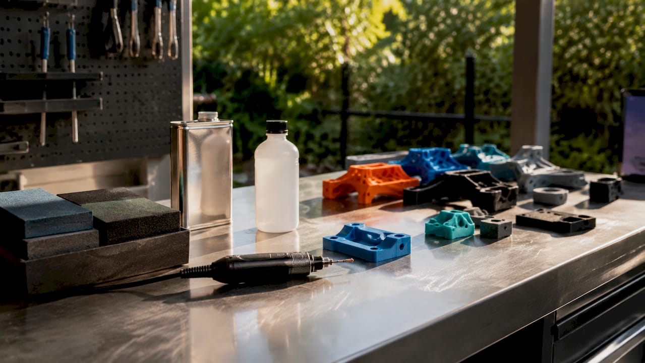
Personalized 3D printed gifts are custom objects manufactured layer by layer with names, photos, or personal designs built directly into the physical form. Unlike a monogrammed mug or an engraved keychain, these gifts are shaped from scratch around the recipient, making every piece a true original. The types of personalized 3D printed gifts available today span figurines, lithophane photo lamps, functional keychains, sculptural home decor, and more. The batch-of-one capability of 3D printing means intricate personalization that mass manufacturing simply cannot replicate. This guide breaks down each major category so you can choose the right gift with confidence.
1. Types of personalized 3D printed gifts: figurines and miniatures
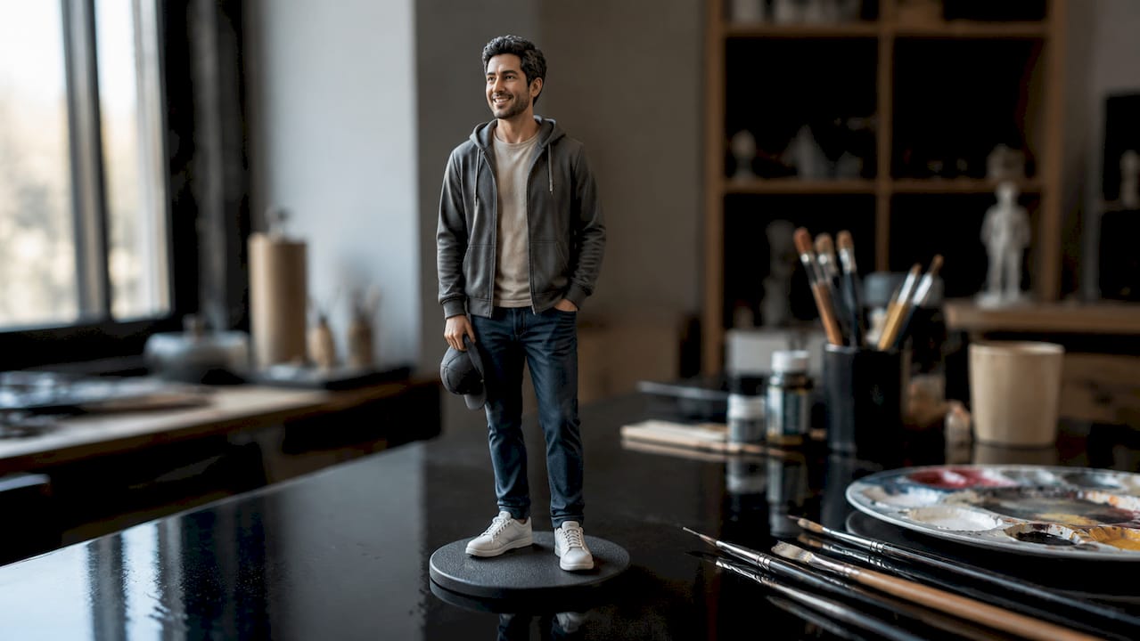
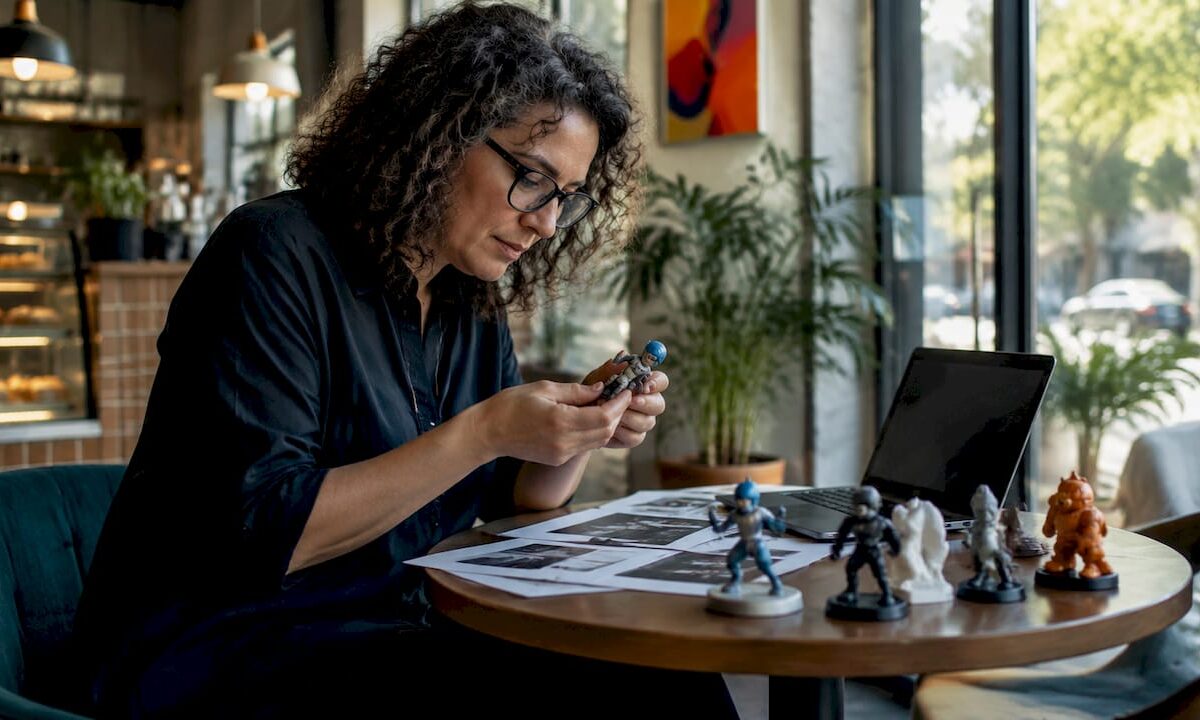
Custom figurines are the most emotionally resonant category in personalized 3D printing. A skilled maker converts a photo or sketch into a photorealistic or stylized miniature of a person, pet, or character, then prints it in SLA resin for fine surface detail. The result is a physical portrait that no photo frame can match.
Popular occasions for custom figurines include:
- Wedding cake toppers modeled from engagement photos
- Pet portraits capturing a dog’s exact fur pattern or a cat’s posture
- Tabletop game pieces shaped like the player’s own character
- Desk tokens for birthdays, retirements, or graduations
Pricing for detailed miniatures runs from $75 to $250 depending on complexity and size. That range reflects the difference between a simple single-figure bust and a full-color multi-figure scene. SLA resin printers, used by services like Cc3dlabs, produce layer resolutions fine enough to capture facial features and fur texture that FDM filament printing cannot achieve at the same scale.
Pro Tip: Send at least two reference photos from different angles. A front-facing photo alone leaves the maker guessing at depth, which affects how accurately the figurine captures the subject’s proportions.
2. Personalized photo gifts: lithophanes and 3D photo lamps
A lithophane is a three-dimensional relief panel that reveals a photographic image only when backlit. The thinner areas of the print let more light through, and the thicker areas block it, creating tonal contrast that forms a recognizable image. The effect is striking in a way that a printed photograph is not, because the image appears to glow from within.
The best photos for lithophanes share three qualities:
- High contrast between subject and background
- Simple composition without cluttered midgrounds
- Sharp focus on the main subject
Printing vertically with white filament is the standard practice for quality lithophanes. Vertical orientation eliminates visible layer lines on the face of the image, and white PLA maximizes light diffusion. A typical lithophane at 0.12mm layer height takes 4 to 5 hours of unattended print time, making it a practical overnight project for a service provider.
| Lithophane form | Best display method | Emotional occasion |
|---|---|---|
| Flat panel | LED light box or window | Memorial, anniversary |
| Curved night light | USB lamp base | Child’s bedroom, nursery |
| Cylindrical lamp shade | Candle or LED pillar | Wedding, holiday gift |
| Coaster set | Backlit coaster holder | Housewarming, birthday |
Pro Tip: Avoid group photos with more than four people for a single lithophane panel. The more faces compressed into one frame, the lower the resolution per face, and the less recognizable the final image.
3. Functional personalized gifts: keychains, phone holders, and cookie cutters
Functional custom 3D printed items are the most accessible entry point for gift-givers on a budget. These are objects the recipient uses every day, which means the personalization stays visible long after the occasion. A keychain with a partner’s name, a phone stand shaped like a favorite animal, or a cookie cutter cut to a child’s initials all deliver daily reminders of the giver.
Key options in this category include:
- Name and date keychains in PLA or PETG, priced from $20 to $60 for small personalized pieces
- Custom phone stands featuring a logo, monogram, or character silhouette as the structural base
- Cookie cutters shaped as names, family crests, or holiday symbols, printed in food-safe PETG or PLA
- Cable organizers and desk accessories with names or motivational text built into the surface
Material choice matters most in this category. Food-safe applications like cookie cutters require PETG or food-grade PLA rather than standard hobby filament, which may contain colorants not rated for food contact. For keychains and phone stands, PETG offers better impact resistance than standard PLA, which can become brittle over time. Cc3dlabs offers material guidance as part of the design process, so you do not need to specify filament grades yourself. Batch printing is also practical here: ordering a set of matching keychains for a wedding party or a team costs less per unit than ordering individually, since the printer can run multiple pieces in a single job.
4. Creative home decor and keepsakes: bookends, vases, and sculptures
Decorative 3D printed gifts occupy a different emotional register than functional items. They are meant to be displayed, which means the design carries the full weight of the sentiment. Custom bookends featuring a couple’s wedding date, a geometric vase generated from a personal prompt, or a sculptural piece commemorating a milestone all serve as permanent visual anchors in a home.
Popular decorative gift options include:
- Custom bookends with names, dates, or meaningful motifs like mountain silhouettes or city skylines
- Geometric vases scaled to a specific shelf or mantel, with surface textures generated from a description
- Memorial sculptures honoring a pet, a person, or a place
- Celebration centerpieces for milestone birthdays or anniversaries
| Decorative gift type | Customization input needed | Best material |
|---|---|---|
| Bookends | Name, date, or silhouette reference | PLA or PETG |
| Geometric vase | Size, color, and texture preference | PLA or resin |
| Memorial sculpture | Photo reference from multiple angles | SLA resin |
| Celebration centerpiece | Theme, dimensions, and color scheme | Multi-color PLA |
Scaling is a practical consideration that many buyers overlook. A sculpture that looks proportionate on screen may be too small to read clearly at 10 centimeters tall, or too large to fit the intended shelf at 30 centimeters. Providing the exact dimensions of the display space when ordering prevents this mismatch. For durable outdoor or high-traffic placements, ASA or PETG outperforms standard PLA, which degrades under UV exposure.
5. Bespoke 3D printed souvenirs and travel keepsakes
Bespoke 3D printed souvenirs are a growing niche within personalized gift ideas, particularly for commemorating travel, events, or shared experiences. A miniature replica of a couple’s first apartment building, a scaled model of a mountain they hiked together, or a custom map relief of a meaningful city all transform a memory into a tangible object.
These gifts work because the subject matter is inherently specific. No off-the-shelf souvenir captures the exact street corner where someone proposed or the precise skyline visible from a childhood bedroom window. The design collaboration process at quality print services starts from reference photos or satellite imagery, with makers refining the geometry digitally before printing. You do not need to supply a CAD file. A clear photo and a description of what matters about the place is enough to start.
Architectural replicas and map reliefs typically require more post-processing than simpler gifts, including sanding and painting to bring out topographic detail. Build that into your timeline. A complex souvenir piece can take three to ten business days beyond the print itself for finishing work.
6. Personalized jewelry and wearable 3D printed gifts
3D printed jewelry sits at the intersection of personal style and custom manufacturing. Rings, pendants, bracelets, and earrings can be printed with initials, coordinates, or geometric patterns that a traditional jeweler would charge significantly more to produce. The design freedom is the key advantage: organic shapes, interlocking structures, and text integrated into the band geometry are all achievable.
For wearable gifts, material selection is the primary decision. Standard PLA is not suitable for jewelry worn against skin over time. Resin prints from SLA printers offer the surface finish needed for jewelry-grade pieces. For metal-look results, services can print in bronze-infused or copper-infused filament, or use the print as a casting pattern for actual metal. Metal casting for a custom piece runs $150 to $500, reflecting the additional labor and material cost. For a gift with lasting sentimental value, that investment is often justified.
7. How to personalize and order custom 3D printed gifts
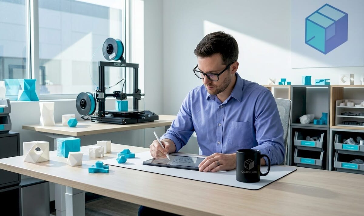
Ordering a custom 3D printed gift does not require technical knowledge. The process at most quality services follows a clear sequence:
- Submit your reference material. A photo, a rough sketch, or a written description is enough to start. Makers prefer a napkin sketch or a clear photo over a finished CAD file, since they refine the design collaboratively with you.
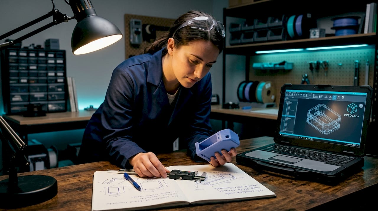
- Review a digital preview. Most services offer a 3D model preview before printing, often for a small fee credited to the final cost. This step eliminates the most common source of disappointment: scale and proportion mismatches.
- Approve and print. Production typically takes one to two days for standard items. Shipping adds five to seven days, so order 9 to 10 days ahead of the occasion to allow for revisions.
- Request a prototype for complex pieces. For multi-part assemblies or intricate designs, a paid prototype catches fit and clearance errors before the final print. Post-processing steps like sanding and painting add three to ten business days.
- Confirm material and finish. Specify whether the gift will be displayed indoors or outdoors, handled frequently, or used with food. These factors determine the right filament or resin.
Pro Tip: When ordering for a specific occasion, add two days to your estimated need-by date as a personal buffer. Shipping carriers miss windows more often during peak gift seasons like December and Valentine’s Day.
The 3D modeling process at Cc3dlabs includes design support from the first inquiry, so you are never left guessing about what to provide or how long the job will take.
Key takeaways
The most effective personalized 3D printed gift combines a strong reference input, the right material for its intended use, and a digital preview before printing to eliminate scale and fit errors.
| Point | Details |
|---|---|
| Figurines need multiple reference photos | Two or more angles produce accurate proportions and better facial detail. |
| Lithophanes require vertical printing | White filament printed vertically eliminates layer lines and maximizes light diffusion. |
| Order 9 to 10 days ahead | Production plus shipping plus revision time requires a full buffer before the occasion. |
| Material choice determines durability | Food-safe items need PETG; outdoor pieces need ASA; jewelry needs SLA resin. |
| Digital previews prevent disappointment | A 3D model preview before printing catches scale and proportion errors before they become costly. |
Why the right input matters more than the budget
I have seen clients spend $200 on a detailed figurine and receive something that barely resembles the subject, and I have seen $30 keychains become someone’s most treasured possession. The difference is almost never the price. It is the quality of the reference material and the communication during the design phase.
The single biggest mistake gift-givers make is submitting one blurry photo and expecting a photorealistic result. 3D printing is not magic. It is geometry. The maker can only model what they can see, and if the reference is ambiguous, the model will be too. Send multiple angles, specify what matters most about the subject, and engage with the digital preview rather than skipping it.
The other mistake is underestimating the emotional weight of the material choice. A memorial sculpture for a lost pet printed in brittle PLA that chips within a year is not the lasting tribute you intended. Spend five minutes discussing material options with your service provider. That conversation costs nothing and changes the outcome significantly.
What makes these gifts genuinely special is the batch-of-one personalization that no retail shelf can offer. A gift shaped around one specific person, moment, or memory carries a weight that a generic present simply does not. That is worth protecting with good inputs and a proper preview.
— Justin
Start your personalized gift project with Cc3dlabs

Cc3dlabs, based near Philadelphia, handles the full process from your first reference photo to the finished print. Their team offers design collaboration, digital model previews, and material guidance so you arrive at a result that matches your vision. Whether you need a single lithophane night light or a batch of custom keychains for a wedding party, Cc3dlabs provides precise online estimates before any commitment. Explore the full range of custom 3D printing services and start your personalized gift project today.
FAQ
What types of personalized 3D printed gifts are most popular?
Custom figurines, lithophane photo lamps, and personalized keychains are the most frequently ordered categories. Figurines suit milestone occasions like weddings and retirements, while lithophanes and keychains work for birthdays and everyday gifting.
How much do custom 3D printed gifts cost?
Small personalized items like keychains run $20 to $60, while detailed figurines and jewelry range from $75 to $250. Metal casting for custom jewelry pieces costs $150 to $500 depending on complexity.
Do I need a CAD file to order a personalized 3D printed gift?
No. Most quality services, including Cc3dlabs, work from reference photos, rough sketches, or written descriptions. Makers refine the design collaboratively and provide a digital preview before printing.
How long does it take to receive a custom 3D printed gift?
Production typically takes one to two days, with shipping adding five to seven days. Order at least nine to ten days before the occasion to allow time for design revisions and any delays.
What is a lithophane and how does it work as a gift?
A lithophane is a 3D printed relief panel that reveals a photograph when held up to light. It is printed in white filament at fine layer heights, and the varying thickness of the material creates tonal contrast that forms the image.