
TL;DR:
- Bridging in 3D printing involves extruding filament horizontally between two anchored points without support structures. Proper cooling, speed, and geometry design are essential to produce strong, sag-free spans, with PLA being the ideal filament for bridging due to its fast cooling. Adjusting slicer settings and redesigning parts can reduce reliance on supports and improve print quality across various filament types.
Bridging in 3D printing is defined as the process of extruding filament horizontally between two anchored points without any material beneath to support it. This technique is central to explaining bridging in 3D printing because it determines whether a design needs support structures or can print cleanly on its own. The industry term is “FDM bridging,” and it applies to any filament-based printer using fused deposition modeling. Most well-tuned FDM printers bridge 50–80mm without supports, while optimized setups exceed 100mm. That range tells you exactly how much geometry you can get away with before supports become unavoidable.
How does bridging work in 3d printing?
Bridging works by pulling extruded filament taut between two fixed anchor points, much like stringing a wire between two posts. The extruder moves across the gap while depositing molten filament, and the key is that the filament must solidify before gravity pulls it down. Without rapid cooling, the strand sags and ruins the surface below.
Bridging differs from overhangs in one critical way: the filament is anchored at both ends, not just one. An overhang extends outward from a single wall with nothing on the far side. A bridge connects two walls, which gives the extruded strand tension on both ends. That tension is what makes bridging physically possible without support.
The cooling system does the heavy lifting. As the nozzle moves across the gap, the part cooling fan blasts the freshly extruded filament to freeze it in place before it can droop. Speed matters here too. Move too fast and the filament snaps or under-extrudes. Move too slow and the filament stays molten too long and sags under its own weight.
Pro Tip: Run a dedicated bridge calibration test before printing your actual part. Files like the “Bridging Test” models on Printables let you dial in speed and cooling on a throwaway print rather than discovering problems mid-job on a complex prototype.
What slicer settings produce the best bridges?
Slicer settings control the outcome of every bridge you print. Getting them right means understanding how cooling, speed, and flow rate interact with each other.
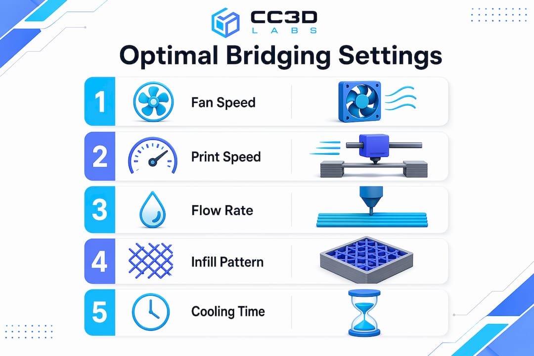
Cooling
Optimal bridging requires 100% fan speed for most materials. The faster the filament solidifies, the less it sags. ABS and ASA are the major exceptions. Those materials require 30% fan speed or less to prevent thermal warping and layer delamination. Pushing full cooling on ABS will crack the part before the bridge even finishes.
Print Speed
Bridging speed typically falls between 20–80 mm/s depending on the printer and filament. Slower speeds give the cooling fan more time to solidify each strand, which improves surface quality. Faster speeds reduce the time filament stays molten mid-air, which can help with tension. Most users find 30–40 mm/s is the sweet spot for PLA on a well-tuned machine.
Flow Rate and Infill Pattern
Reducing bridge flow to 80–95% prevents excess molten material from building up mid-span. Less material means less weight pulling the strand down. Concentric bridge infill patterns also outperform linear ones because they distribute tension more evenly across the span. Slicers like Simplify3D, PrusaSlicer, and Cura all offer dedicated bridge settings menus where you can override these values independently from the rest of the print.
Pro Tip: Some advanced users push external bridge flow rates up to 140–150% combined with slower speeds. Higher flow rates at lower speeds can improve strand bonding by expanding filament laterally, creating a more uniform surface. Test this on scrap prints first.
What are the most common bridging problems?
Bridge failures follow predictable patterns. Knowing the cause cuts your troubleshooting time in half.
-
Sagging strands. The most common failure. Caused by insufficient cooling, excessive print temperature, or a span that exceeds the printer’s capability. Drop your print temperature by 5°C and increase fan speed before changing anything else.
-
Stringing across the gap. Happens when retraction settings are not tuned for bridging. The nozzle oozes material as it travels, leaving thin threads across the span. Increase retraction distance slightly and reduce travel speed.
-
Drooping at the center. A longer span issue. The filament holds at the anchors but sags in the middle. Shorten the span through part redesign, or split the bridge into two shorter sections with a mid-span support column.
-
Inconsistent extrusion. The bridge looks uneven or has gaps. Hardware issues like clogged nozzles or wet filament produce extrusion inconsistencies that mimic slicer setting errors. Dry your filament and clean the nozzle before adjusting any parameters.
-
Warping at bridge edges. Common with ABS and ASA. The rapid temperature change at the bridge edges causes the corners to lift. Reduce cooling, increase bed temperature, and consider an enclosure.
Pro Tip: Bridge failures often signal cooling or geometry issues rather than a simple settings error. Always check hardware first. A partially clogged nozzle will make every bridge look like a settings problem when the real fix is a cold pull.
How does filament type affect bridging?
Every filament behaves differently mid-air. Matching your settings to your material is non-negotiable for consistent results.
-
PLA is the best material for bridging. It cools fast, holds tension well, and tolerates 100% fan speed without warping. Most bridging benchmarks and tutorials use PLA as the baseline. If you are learning to tune bridges, start here.
-
ABS and ASA require a fundamentally different approach. Full cooling causes warping and layer separation. Keep fan speed at 30% or below, slow the bridge speed to 20–25 mm/s, and use an enclosure to maintain ambient temperature. Bridging spans with ABS should be kept shorter than with PLA. For a deeper look at how these materials compare, the PLA vs. PETG vs. ABS guide from Cc3dlabs covers mechanical trade-offs in detail.
-
PETG sits between PLA and ABS in bridging difficulty. It strings aggressively and stays tacky longer than PLA, which causes strands to sag and stick to each other. Reduce flow to 80%, increase retraction, and run fan speed at 50–70%. Expect more post-processing cleanup on PETG bridges.
-
Flexible filaments like TPU are nearly impossible to bridge cleanly. The material stretches under tension instead of holding taut. For flexible parts with horizontal spans, support structures are the only reliable option.
The pattern across all materials is the same: faster cooling and lower flow rates improve bridge quality, but each material has a ceiling on how much cooling it can tolerate before other problems appear.
Design strategies that reduce bridging problems
Smart geometry eliminates many bridging problems before the print even starts. The table below compares common design approaches and their trade-offs.
| Strategy | Best For | Trade-Off |
|---|---|---|
| Add chamfers at 45° | Replacing flat bridges with angled surfaces | Slightly changes part geometry |
| Split bridge into segments | Long spans over 60mm | Requires mid-span support columns |
| Reorient the part | Shortening bridge direction | May increase total print height |
| Reduce span width in CAD | All bridging scenarios | Requires design iteration |
| Use a teardrop hole shape | Circular holes on vertical faces | Changes hole aesthetics |
Part redesign to reduce bridge span is the preferred approach in batch production because it eliminates post-processing labor and reduces failure rates at scale. Adding a 45° chamfer to the underside of a horizontal feature converts a flat bridge into a series of short overhangs, which most printers handle without any special settings. For production-focused design decisions, the 3D part optimization guide from Cc3dlabs walks through geometry choices that reduce support dependency across entire part families.
Reorienting the part on the build plate is often the fastest fix. A span that runs 80mm in one orientation might only run 30mm when the part is rotated 90°. That single change can move a print from “needs supports” to “prints clean” with zero CAD edits. For low-volume production runs, the low-volume manufacturing guide covers when orientation changes deliver the most value.
Key takeaways
Successful bridging in FDM printing depends on matching cooling, speed, and flow rate to your specific material, then designing geometry that keeps spans within your printer’s capability.
| Point | Details |
|---|---|
| Standard bridging span | Most FDM printers handle 50–80mm cleanly; optimized setups exceed 100mm. |
| Cooling is the primary lever | Run 100% fan speed for PLA; limit ABS and ASA to 30% or less to prevent warping. |
| Flow rate matters | Set bridge flow to 80–95% to reduce mid-span sag and excess material buildup. |
| Check hardware before settings | Clogged nozzles and wet filament mimic slicer errors; fix hardware first. |
| Design beats troubleshooting | Chamfers, part reorientation, and shorter spans outperform support structures in production. |
What i’ve learned after years of watching bridges fail
The most common mistake I see is treating bridging as a pure settings problem. Someone gets a saggy bridge, opens their slicer, and starts adjusting fan speed and flow rate for an hour. Then they discover the filament spool has been sitting open for three weeks and absorbed moisture. Wet filament produces inconsistent extrusion that no slicer setting can fix. Dry your filament first. Clean your nozzle. Then tune settings.
The second thing I’ve changed my mind on is supports. Early in my experience, I added supports liberally because they felt like a safety net. Now I treat them as a last resort. Every support structure adds post-processing time, leaves surface marks, and increases material cost. A well-placed chamfer or a 10-minute CAD edit almost always beats an hour of support removal and surface cleanup. For anyone running batch production, that math compounds fast.
The emerging trend worth watching is higher bridge flow rates. Pushing flow to 140–150% combined with slower speeds is counterintuitive, but the logic holds. Wider strands bond to each other more effectively, creating a more solid surface. I’ve tested this on PLA with good results, though it requires careful calibration to avoid over-extrusion at the anchor points. It is not a setting to deploy without testing, but it is worth experimenting with on complex geometries.
My overall advice: be methodical. Change one variable at a time, run a calibration print, and document what you observe. Bridging is solvable for almost any geometry if you approach it systematically rather than randomly adjusting sliders.
— Justin
Get professional help with complex print geometry
When bridging challenges are holding back your prototype or production timeline, Cc3dlabs has the equipment and expertise to handle it.

Cc3dlabs, based near Philadelphia, specializes in custom filament-based 3D printing for prototypes, functional parts, and batch orders. The team tunes print parameters for each job, including bridge-specific settings, cooling profiles, and part orientation, so you get clean results without the trial-and-error cycle. Whether you need a single prototype or a production run with complex geometry, Cc3dlabs offers free online estimates, design support, and fast turnaround. Reach out to discuss your project and get a print that performs.
FAQ
What is bridging in 3d printing?
Bridging is the process of extruding filament horizontally between two anchored points without support material beneath. It is a standard FDM technique used to print horizontal spans cleanly without adding support structures.
How long of a bridge can a 3d printer handle?
Most well-tuned FDM printers handle spans of 50–80mm without supports. Optimized machines with dialed-in cooling and speed settings can exceed 100mm.
What is the best filament for bridging?
PLA is the best filament for bridging because it cools fast, holds tension well, and tolerates 100% fan speed. ABS, ASA, and PETG require lower cooling and more careful tuning.
Why does my bridge keep sagging?
Sagging is most often caused by insufficient cooling, excessive print temperature, or a span that exceeds your printer’s capability. Check for wet filament or a clogged nozzle before adjusting slicer settings.
Should i use supports instead of bridging?
Supports should be reserved for genuine geometry challenges after you have optimized cooling, speed, and part orientation. Redesigning the part with chamfers or shorter spans almost always produces better results than adding supports.