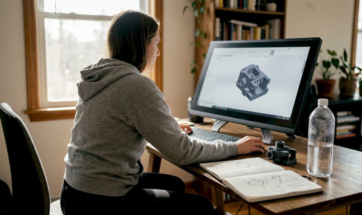
Designer working on 3D model at home workspace

What Is 3D Art Design? Key Concepts for Prototyping


TL;DR:

  • 3D art design combines visual appeal with functional geometry for manufacturable prototypes.
  • Successful printing relies on proper technical parameters, validation, and iterative testing.
  • Integrating artistic judgment, engineering, and manufacturing awareness ensures high-quality, print-ready models.

Most businesses treat 3D art design as a visual exercise — something you do to make a product look good on screen before handing it off to engineering. That assumption costs time, money, and failed prints. Vital role in prototyping is what separates teams that iterate fast from those stuck in endless revision cycles. This guide breaks down what 3D art design actually means for product developers, how the workflow runs from concept to print-ready file, which technical parameters determine real-world part performance, and what pitfalls to avoid before you ever load a spool of filament.

Table of Contents

Key Takeaways

Point Details
3D art design explained It integrates creativity with engineering to turn digital models into printable, functional objects.
Workflow matters Using the right mix of CAD and AI tools ensures designs are accurate and ready for manufacturing.
Technical choices drive quality Infill density, layer height, and geometry corrections greatly influence prototype strength and print success.
Fix design errors early Address issues like thin walls and non-manifold geometry in the design phase to avoid costly print failures.

Defining 3D art design: Purpose and scope

Strip away the aesthetics conversation and 3D art design becomes something very precise: it is the discipline of creating digital three-dimensional geometry that serves both visual and functional goals. Unlike a 2D illustration or a rendered product concept, a 3D art design file carries spatial data — wall thickness, internal geometry, surface topology — that directly controls how a physical object gets manufactured.

For businesses and product developers, the distinction matters enormously. A designer who only thinks in terms of appearance will produce files that look stunning in a render and fail catastrophically on the print bed. A developer who only thinks in terms of engineering tolerances may produce parts that are accurate but lack the surface quality or aesthetic cohesion needed for a marketable prototype. The strongest 3D art designs sit at the intersection of both.

3D art design translates creative and engineering concepts into digital files ready for custom 3D printing and manufacturing. That translation process is where most of the real work happens — converting a sketch, a scan, or an idea into a watertight mesh that a slicer can process without errors.

Here is what 3D art design actually produces in a business context:

  • Product prototypes: Functional mockups that test form, fit, and mechanical behavior before committing to tooling
  • Artistic fabrication parts: Custom sculptures, branded objects, or decorative components with precise dimensional accuracy
  • Engineering mockups: Assembly verification models that confirm spatial relationships between components
  • Batch production masters: Reference parts used to validate consistency across a production run

“The digital model is not the end product — it is the manufacturing instruction. Every decision you make in the design file shows up in the finished part.”

You can see how these outputs look in real applications by browsing our 3D modeling gallery, which shows the range of projects that move from digital concept to physical prototype. Understanding the vocabulary behind these workflows also helps — getting familiar with 3D printing terminology early prevents costly miscommunications between designers and print technicians.

Core workflows in 3D art design: From idea to printable model

Once you know what 3D art design is, the next step is understanding how ideas turn into print-ready files. Here is how modern businesses convert concepts to physical parts.

The standard workflow follows four stages:

  1. Ideation and reference gathering: Sketches, reference images, scan data, or engineering specifications define the geometry constraints and aesthetic intent before any software opens.
  2. Modeling and geometry construction: Either parametric CAD software or mesh-based sculpting tools (including AI-assisted platforms) are used to build the 3D geometry. This is where file quality diverges sharply based on tooling choices.
  3. Validation and mesh repair: The model is checked for printability errors — non-manifold geometry, inverted normals, open surfaces. Any issues get resolved before export.
  4. File preparation and export: The clean model exports as STL, OBJ, or 3MF depending on the print service’s requirements. 3MF is increasingly preferred because it carries color, material, and unit data inside a single file.

The biggest decision point sits at step two: AI-assisted tools versus parametric CAD.

Feature AI tools (e.g., Meshy, Wonder3D) Parametric CAD (e.g., Fusion 360)
Speed of ideation Very fast Moderate
Dimensional accuracy Low to moderate High
Mesh quality Often error-prone Clean and watertight
Editing flexibility Limited Full parametric control
Best use case Concept exploration Production-ready prototypes

AI tools accelerate ideation but often create error-prone meshes needing CAD repair for printability. Parametric CAD tools like Fusion 360 remain superior for precise prototypes because they build geometry from defined constraints rather than interpolated surface data.
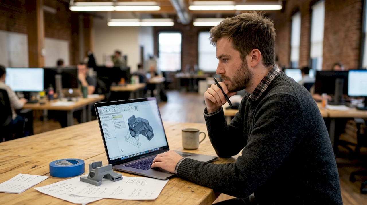
Engineer reviewing 3D mesh repair tools

For businesses, the practical answer is often a hybrid approach: use AI tools to generate a fast concept, then rebuild critical geometry in CAD for accuracy.

Pro Tip: Always run your STL file through a mesh repair tool like Meshmixer or Netfabb before submitting it for printing. Even CAD-generated files can develop small errors during export that cause slice failures.

Understanding print accuracy for prototypes before you finalize your file saves significant rework time. A step-by-step 3D printing workflow that accounts for file validation at each stage dramatically improves first-print success rates.

Essential technical factors: What makes a design printable and strong

Understanding the workflow is half the story. For real prototype or product success, you need to master several technical details that have measurable, documented effects on print outcomes.

The parameters that matter most:

Parameter Effect on prototype Recommended range
Infill density Drives tensile, compression, and impact strength 20% to 60% for most functional parts
Layer height Controls surface roughness and Z-axis detail 0.1 mm to 0.3 mm
Wall thickness Determines shell rigidity and surface finish Minimum 1.2 mm for structural parts
Print orientation Governs anisotropic strength distribution Orient load-bearing axis away from Z

Infill density impacts tensile strength by 55%, compression strength by 81%, and impact strength by 64% in PLA. That is not a marginal difference — going from 20% to 60% infill is an engineering decision, not a print setting.
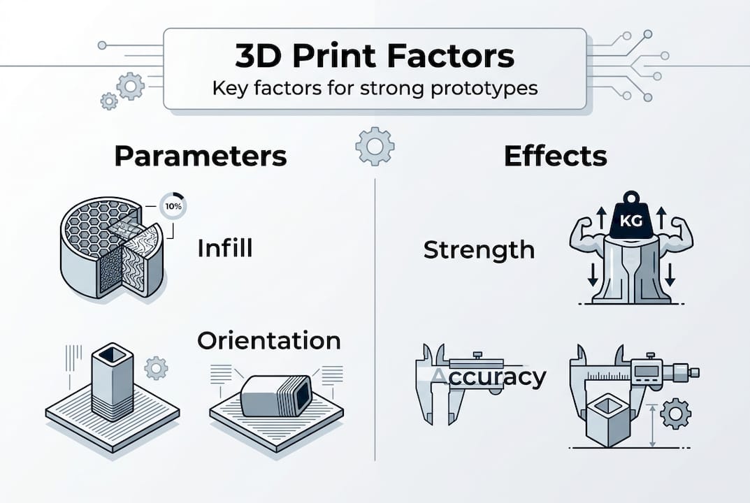
Infographic showing key 3D print design factors

Infill pattern also matters more than most teams realize. Gyroid infill boosts bending modulus 15 to 35% compared to honeycomb, making it the better choice for parts that will experience lateral load. Layer thickness affects both surface roughness and hardness. And Z-axis strength remains anisotropic — parts printed vertically are significantly weaker along their build direction than parts printed flat.

Common design mistakes that create problems:

  • Thin walls below 0.8 mm: The slicer may not generate any toolpath at all, leaving structural voids
  • Overhangs steeper than 45 degrees: Without support structures, these collapse during printing
  • Tolerances tighter than 0.2 mm: Material shrinkage and thermal expansion make sub-0.2 mm tolerances unreliable in FDM printing
  • Ignoring warping on large flat bases: Parts with large footprints need brim settings or material choices that resist bed separation

The good news is that all of these are preventable at the design stage. Resources on designing reliable prototypes and low-volume manufacturing tips give you specific geometry guidelines that catch these issues before manufacturing begins.

Design pitfalls and advanced solutions: Getting print-ready for custom parts

Even with the right technical setup, custom part designs can present tough edge cases. Here is how to address and solve them for a successful print.

The most common problem categories and their solutions:

  • Non-manifold geometry: Surfaces that share an edge or overlap internally confuse slicers. Fix with Meshmixer’s Inspector tool or Netfabb’s automatic repair. Always verify with a manifold check before export.
  • Thin walls and fragile features: Features below 1.2 mm wall thickness may not print cleanly. Add material to thin features or redesign with a minimum feature size that matches your nozzle diameter.
  • Sharp overhangs above 45 degrees: Add chamfers or fillets at transition points. A 1 mm to 2 mm fillet at a sharp edge reduces the overhang angle and eliminates the need for support material in most cases.
  • Shrinkage and warping on large parts: Choose materials with lower thermal expansion (like PETG over ABS for moderate-temperature applications) and include a brim in your slicer settings for large flat footprints.
  • Over-tight assembly tolerances: Design-in clearance gaps of at least 0.2 mm to 0.3 mm between mating parts. Test fit with a single-layer print of the mating interface before committing to the full print.
  • Draft angle omission: Parts designed for injection molding often lack draft angles, which causes adhesion problems on vertical walls during FDM printing. Add 1 to 2 degree draft angles to vertical faces wherever possible.

Non-manifold geometry, thin walls, sharp overhangs, and over-tight tolerances are the leading causes of print failure for custom parts. The fix in almost every case starts with catching the error in the file, not on the printer.

Pro Tip: Before submitting a complex prototype for full production, run a scaled-down test print at 50% size. This validates the geometry, support structures, and layer adhesion in a fraction of the time and material cost of a full-size print.

For unfamiliar geometry types or advanced material requirements, 3D printing jargon defined is a practical reference that clears up terminology confusion between design teams and print specialists. For parts that need to meet strict functional standards, exploring engineering-grade printing options ensures the material and process match the application.

Our perspective: Why mastering 3D art design means thinking beyond the model

Here is what most businesses and product teams miss when approaching 3D art design: a beautiful model is not a manufacturable product. We see it consistently — teams invest heavily in high-end rendering and visual design, then submit a file that fails the first slicer check because no one validated it against print constraints.

The uncomfortable truth is that 3D art design for prototyping requires three disciplines to work together: artistic judgment, engineering precision, and manufacturing awareness. Drop any one of them and your output quality drops. A stunning geometry that ignores layer adhesion mechanics will break under functional load. An accurate CAD file that ignores aesthetics produces a prototype nobody wants to show to stakeholders.

What separates successful teams is iterative, test-driven thinking. They design for the print process, not around it. They run test prints, measure results against specifications, and feed that data back into the next design revision. That loop — design, print, measure, revise — is where real innovation happens. Browsing best 3D print jobs gives you a reference point for what that discipline produces in practice.

How CC3DLabs can turn your design vision into reality

Ready to put world-class 3D art design to work for your business? At CC 3D Labs, we work with product developers and businesses near Philadelphia and across the country to transform high-quality 3D art designs into precise, functional prototypes and custom parts.

https://cc3dlabs.com

Our team handles everything from CAD validation and mesh repair to full-run production using advanced filament-based printing. Whether you need a single concept prototype or a batch of functional parts, our 3D printing services are built for accuracy and fast turnaround. Not sure what your design can produce? Explore what you can print to see the range of applications we support, or jump straight into print on demand to get your project moving with a free online estimate.

Frequently asked questions

What is the difference between 3D art design and regular 3D modeling?

3D art design combines artistic and engineering principles to produce geometry that is both visually resolved and manufacturable, while standard 3D modeling often targets digital-only assets without accounting for physical production constraints. 3D art design translates creative concepts directly into files ready for custom manufacturing.

Why do AI tools for 3D art design need CAD repair before printing?

AI-generated meshes commonly contain non-manifold geometry, surface gaps, and inverted normals that cause slicer failures. CAD repair tools rebuild the mesh structure to make the model watertight and dimensionally accurate. AI tools accelerate ideation but consistently require post-processing before any file is print-ready.

Which technical factor most affects the strength of 3D printed prototypes?

Infill density and print orientation have the greatest combined impact on prototype strength. Infill density impacts tensile strength by 55%, compression by 81%, and impact resistance by 64% in PLA, making it the single highest-leverage parameter in the slicer settings.

What common design pitfalls can ruin 3D print quality?

Thin walls below 0.8 mm, non-manifold geometry, overhangs above 45 degrees, and assembly tolerances tighter than 0.2 mm are the most frequent causes of failed or unusable prints. Non-manifold geometry, thin walls, and over-tight tolerances can all be caught and corrected during the design validation stage before manufacturing begins.
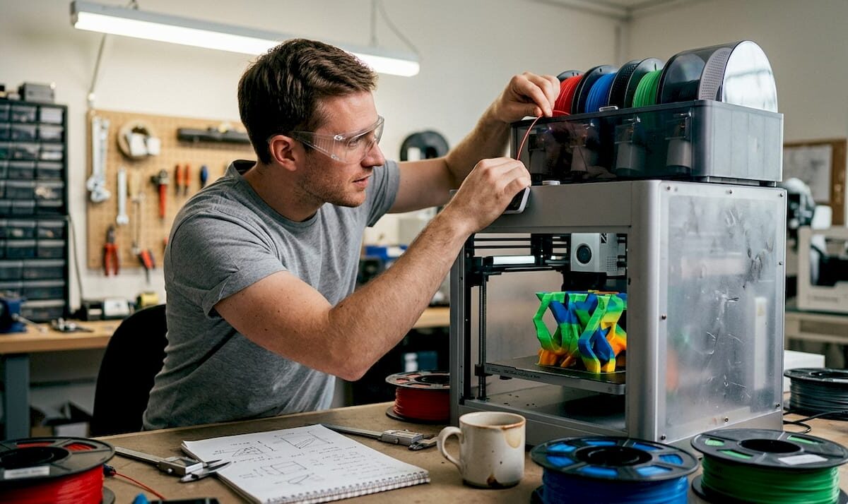
Technician adjusting multi-color 3D printer on workbench

Multi-color 3D printing: methods, challenges, and value


TL;DR:

  • Multi-color 3D printing involves complex methods with tradeoffs in cost, waste, and reliability.
  • Workflow discipline, including filament storage and model preparation, is crucial for success.
  • Choosing the right method depends on your project needs, volume, and desired color fidelity.

Multi-color 3D printing looks like a straightforward upgrade. Add more colors, get better prototypes. Done. Except it rarely works that way. The technology that makes your product models pop with realistic branding and vivid detail can also consume up to 50% more raw filament through purging alone, stall your production timeline, and introduce failure risks that only show up halfway through a 14-hour print. For business owners and product developers, understanding the true mechanics and tradeoffs is the difference between a compelling prototype and a costly mistake.

Table of Contents

Key Takeaways

Point Details
Waste impacts cost Multi-color 3D printing processes can waste up to 50% more material, raising project expenses.
Workflow matters Using dry filament and well-tuned slicer settings is critical for reliable, high-quality multi-color prints.
Tech choice is key AMS, independent nozzle, and toolhead systems each offer unique tradeoffs for business use.
Plan for application Choose your multi-color method based on your product’s needs, volume, and visual requirements.

What is multi-color 3D printing?

Once you understand why multi-color prints attract attention, it’s essential to grasp exactly how these technologies work and what sets them apart.

At its core, multi-color 3D printing is the ability to produce a single printed object using two or more filament colors or materials in one print session. Unlike painting or post-processing, the color is built directly into the part during fabrication. That makes it ideal for product logos, realistic concept models, client presentation pieces, and branded components that need to communicate design intent without extra finishing steps.

Standard single-extruder printers work with one color of filament from start to finish. Multi-color setups break that constraint. The main approaches include:

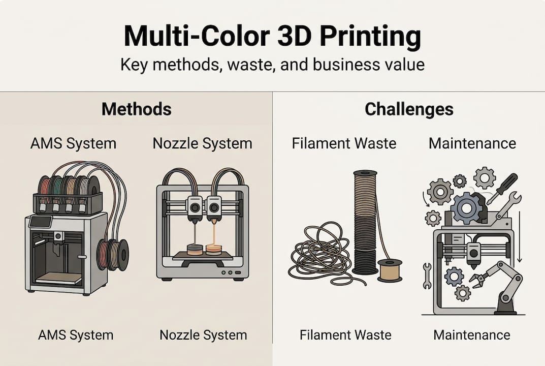
  • Single-extruder with material switching: An automated device like an AMS (Automatic Material System) feeds different filament colors into the same nozzle. The printer purges old color before switching. Simple, but wasteful.
  • Multi-extruder or independent printhead systems: Each nozzle carries a different color or material. No purging needed between colors, and both can print simultaneously.
  • Tool-changing systems: A robotic carriage swaps entire printheads mid-print. Extremely precise, but more mechanically complex.
  • Full-color inkjet-style 3D printing: Binder jetting or similar processes deposit colored binders layer by layer. Highest color fidelity, but limited material strength.

For 3D printing on demand, the FDM-based methods dominate because they support functional materials like PETG, TPU, and engineering-grade filaments that clients actually need.

Here is where the first hard reality lands:

“Color changes in basic FDM setups are limited to layer-aligned boundaries. Vertical color splits within a single layer require multi-extruder or tool-changing setups. Common failure points include color bleeding from incomplete purging, wet filament jams in AMS units, and non-manifold geometry errors in AI-generated models.”

For business prototypes, this means your slicer settings, model geometry, and filament condition matter as much as the hardware itself. Rushing any of these steps produces prints that look impressive in a render but fall apart in the build chamber.

How multi-color 3D printing works: Key methods compared

After covering what multi-color 3D printing is, the next step is comparing how the main methods perform in a real-world, business-relevant context.

The method you choose determines your cost per part, your waste rate, your failure risk, and ultimately whether your multi-color workflow makes financial sense at scale. Here is a direct comparison:

Method Filament waste Print speed Color accuracy Maintenance load
AMS single-nozzle 30 to 50% extra Moderate Moderate (purge dependent) Low to moderate
Independent multi-nozzle Low (up to 90% less waste) High (up to 800 mm/s) High Moderate
Tool-changing (e.g., Prusa XL) Minimal Moderate Very high Higher
Full-color inkjet Minimal Slow Highest High

AMS systems waste 30 to 50% of extra filament on purges, while systems like the MOVA Palette 300 cut that waste by up to 90% through independent nozzles. Tool-changing systems eliminate purging entirely, and advanced multi-nozzle setups reach print speeds up to 800 mm/s.

Engineer removing wasted filament from printer

For most businesses running a handful of color prototypes per week, AMS setups offer an accessible entry point. But as your run volume grows or your color count increases beyond four, the filament 3D printing economics shift fast. Waste filament is paid filament. At 30 to 50% extra consumption, a $40 material run becomes a $60 one before you factor in failed prints.

Independent nozzle systems cost more upfront but pay back quickly when you factor in reduced waste, faster cycle times, and fewer failed prints. If you are producing client-facing demos, validation prototypes, or small-batch branded parts, that investment compounds.

Pro Tip: Before buying hardware, calculate your projected monthly filament spend at a 40% waste rate. That number alone often justifies upgrading to an independent nozzle or tool-changing system, or outsourcing to a custom filament printing specialist who already runs optimized equipment.

Workflow pitfalls and how to solve them

So, how do you actually operationalize these systems and avoid common errors that can undermine even the most promising prototypes?

The technical capability exists. The workflow discipline is what separates successful multi-color shops from expensive ones. Here are the most common failure points and how to fix them:

  1. Wet filament jams: Moisture-absorbed filament causes bubbling, weak layers, and nozzle clogs. This is the leading cause of failed multi-color prints. Store all filament in sealed containers with desiccant, and dry spools before extended print jobs.
  2. Incomplete purging: When the previous color is not fully flushed from the nozzle, you get color bleeding that ruins logos and brand elements. Increase purge volumes in your slicer, even if it raises waste temporarily.
  3. Poor model geometry: AI-generated models often contain non-manifold geometry, which causes slicer errors and mid-print failures. Always run your STL through a mesh repair tool like Meshmixer or Netfabb before slicing.
  4. Slicer misconfiguration: Wrong retraction settings, color transition zones placed incorrectly, or inadequate purge towers cause visible artifacts. Calibrate slicer profiles specifically for each filament type and color combination.
  5. Underestimating print duration risk: Every additional hour of print time increases failure probability. Low-volume manufacturing runs benefit from scheduling shorter multi-color jobs when possible and monitoring long prints with webcam feeds.

Business trade-offs are real: waste in the 30 to 50% range drives up costs fast in high-volume scenarios, independent nozzle systems cut that by 90%, and longer prints increase failure risk. Prioritize dry filament and tuned slicers before blaming the hardware.

Pro Tip: Plan your purging towers and color transition zones during the design phase, not after slicing. When color change locations are built into the model architecture, you get cleaner transitions and less guesswork during print setup. Review filament-based prototype examples to see how transition planning affects final part quality.

Business impact: Choosing the right solution for your product development

Solving technical hurdles is only half of the journey. Here is how these choices impact real business results and ROI.

The right multi-color method depends on your production context. Here is a simplified cost and use-case comparison to guide your decision:

Scenario Best method Waste impact Ideal for
1 to 3 colors, low run volume AMS single-nozzle 30 to 50% extra Early-stage prototypes
4+ colors, client presentation pieces Independent multi-nozzle Up to 90% less Product demos, branding
Mixed materials, functional validation Tool-changing system Minimal Engineering prototypes
Highest color fidelity, artistic pieces Inkjet-style 3D printing Minimal Display models

Waste drives costs by 30 to 50% in high-volume AMS setups, while independent nozzle systems cut waste by up to 90% and toolhead systems remain superior for multi-material prototypes.

For small-batch client work, the visual impact of accurate multi-color parts accelerates stakeholder buy-in and reduces revision cycles. That is real time saved. For higher-volume runs, the math on waste versus hardware investment becomes critical to your pricing model.

Key decision factors to evaluate before committing:

  • How many distinct colors does your typical prototype require?
  • What is your average print duration, and how does failure risk affect your deadline?
  • Are you producing display models or functional, tested parts?
  • Is waste filament cost currently included in your per-part pricing?
  • Would outsourcing to a specialist reduce total cost compared to in-house hardware?

Explore the full range of applications of 3D printing and review 3D printing trends shaping how businesses are deploying multi-color capabilities in 2026 to benchmark your own approach.

The real cost and opportunity of multi-color 3D printing: A practitioner’s view

Here is the uncomfortable truth we see play out regularly: businesses invest in multi-color hardware because it looks impressive, then spend the next six months troubleshooting waste, jams, and failed prints. The technology gets blamed. But the real issue is almost always workflow and process maturity.

More colors do not automatically produce better prototypes. A two-color print with clean geometry, dry filament, and a calibrated slicer will beat a six-color print with a sloppy workflow every time. Business trade-offs are stark: waste in the 30 to 50% range compounds fast, longer prints increase failure risk, and the organizations that get the best results prioritize process discipline over hardware specs.

Infographic showing multi-color 3D printing methods and challenges

The overlooked opportunity here is stakeholder engagement. A precise, well-executed multi-color prototype shortens your feedback loop and gets decisions made faster. That speed-to-validation advantage is worth more than the print itself. Before upgrading your printer, upgrade your multi-color printing workflow. Dry your filament. Tune your slicer. Fix your geometry. Then evaluate whether your current equipment is actually the bottleneck.

Explore advanced multi-color 3D printing with CC3DLabs

Ready to go beyond the basics? Here is how we can help accelerate your innovation.

At CC 3D Labs, we run production-grade multi-color and multi-material printing workflows built specifically for business owners and product developers who need accurate, repeatable results without the overhead of managing complex hardware in-house.

https://cc3dlabs.com

Our 3D printing services cover everything from early-stage concept models to small-batch branded components, with optimized setups that minimize material waste and maximize color accuracy. Whether you need a fast-turnaround consultation on what can be printed for your next prototype or a full on-demand prototyping run, our team is ready to scope your project, estimate costs, and get your parts moving. Reach out for a free online estimate today.

Frequently asked questions

How does multi-color 3D printing work with a single extruder?

A single-extruder printer uses an automated filament-switching device to load different colors into the same nozzle at set layer points. AMS systems waste 30 to 50% of extra filament in purge cycles, which limits its efficiency for high-volume runs.

Is multi-color 3D printing good for making functional parts?

For most functional applications, material properties matter more than color, but advanced multi-nozzle systems can produce durable, accurate prototypes with color integrated. Toolhead systems are superior when combining different materials in a single functional part.

What is the biggest challenge with multi-color 3D printing?

Material waste from color purging and the compounding failure risk on long multi-color print jobs are the primary challenges. Longer prints increase failure risk, making process discipline and filament condition critical to every run.

Does multi-color 3D printing cost more than regular printing?

Yes. Between increased material consumption and more complex hardware requirements, the cost per part is higher. Waste drives costs by 30 to 50% in standard AMS setups, which must be factored into your pricing from the start.

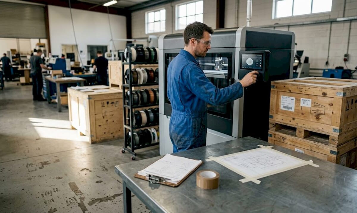
Technician adjusts industrial 3D printer on factory floor

Manufacturing-grade 3D printing: a guide for production


TL;DR:

  • Manufacturing-grade 3D printers are designed for production with high repeatability and process control.
  • Seven ISO/ASTM recognized AM processes match specific applications, materials, and accuracy needs.
  • Successful industrial use depends on robust process validation and quality management, not just machine specs.

Most engineers assume any 3D printer can handle production work if the settings are dialed in correctly. That assumption costs time, money, and credibility. Manufacturing-grade 3D printing operates under an entirely different set of requirements, from material traceability and process repeatability to factory-floor integration and in-process quality monitoring. This guide breaks down exactly what separates industrial additive manufacturing (AM) from desktop and prototyping systems, covers the seven ISO/ASTM-recognized AM processes, compares equipment tiers side by side, and connects those facts to real-world applications in aerospace, medical, automotive, and electronics. By the end, you will know how to evaluate systems and make confident technology decisions for your next project.

Table of Contents

Key Takeaways

Point Details
Not all 3D printers are alike Manufacturing-grade 3D printers deliver high reliability, precision, and repeatability that desktop models can’t match.
Seven AM processes matter Understanding ISO/ASTM methods unlocks the right manufacturing-grade solution for your application.
Accuracy and monitoring are crucial Production-grade systems ensure process control for functional, end-use parts every time.
Choose methods for the outcome Selecting the right AM technology accelerates prototyping and low-volume production with minimal compromises.

Defining manufacturing-grade 3D printing

Not every machine that melts filament or cures resin qualifies as a manufacturing-grade system. The distinction matters enormously when you are designing parts that must pass validation, meet regulatory standards, or ship inside a finished product.

Manufacturing-grade 3D printing refers to industrial AM systems designed for production use, emphasizing repeatability, throughput, controlled materials, in-process monitoring, and auxiliary equipment for factory integration. That definition draws a hard line between systems built to produce consistent, documented output and systems built to make one-off prints quickly.

So what does that actually look like in practice? Here are the core elements that define a manufacturing-grade system:

  • Repeatability: Part dimensions and mechanical properties remain consistent across a full production batch and across multiple build cycles over time.
  • Throughput: Systems are designed to run continuously or at high duty cycles without compromising output quality.
  • Controlled material handling: Feedstocks are qualified, certified, and handled under strict conditions to prevent moisture absorption, contamination, or property drift.
  • In-process monitoring: Sensors, cameras, and closed-loop feedback systems catch deviations during the build, not after the part comes off the machine.
  • Factory integration: Industrial AM equipment connects to ERP systems, quality management software, and downstream automation for traceability from raw material to finished part.

“Manufacturing-grade 3D printing is not about a single machine capability, it is about the entire production system operating predictably, documentably, and repeatably within a quality-controlled environment.”

For product developers, understanding 3D printing terminology is the first step toward making informed decisions about which systems belong in a manufacturing workflow. A printer that works brilliantly for a proof-of-concept prototype may introduce unacceptable variance the moment you scale to 500 units. That gap between prototyping capability and production reliability is where projects stall and where manufacturing-grade systems deliver their real value.

Key methodologies: Seven core AM processes

Having defined what makes a system manufacturing-grade, let’s look at the main additive manufacturing methods recognized by standards organizations.

ISO and ASTM jointly classify AM into seven process categories, each with distinct material compatibility, accuracy ranges, and production suitability. Understanding these categories helps you match the process to your part requirements rather than defaulting to whatever technology you have access to.

  1. Powder Bed Fusion (PBF): Includes SLS, HP Multi Jet Fusion (MJF), and DMLS. A laser or energy source selectively fuses powdered material layer by layer. This is the dominant method for industrial polymer and metal production.
  2. Binder Jetting: A liquid binding agent selectively joins powder particles. No heat during the build, which reduces warping. Used for metal, sand, and ceramic parts.
  3. Directed Energy Deposition (DED): Melts material as it is deposited, typically for large metal parts or repair applications. Common in aerospace and defense.
  4. Material Extrusion (industrial FDM): The industrial version of desktop FDM uses high-temperature materials like ULTEM and PEEK in enclosed, thermally controlled chambers.
  5. Material Jetting: Droplets of photopolymer are jetted and cured layer by layer, delivering extremely fine detail and multi-material capability.
  6. Sheet Lamination: Layers of material (metal foil, paper, or plastic) are bonded and cut to shape. Used in specialized tooling applications.
  7. Vat Photopolymerization (SLA/DLP): A UV light source cures liquid resin, producing high-surface-quality parts often used in dental, medical, and consumer product industries.
Process Primary materials Typical accuracy Best application
Powder Bed Fusion Polymers, metals ±0.1 to ±0.3 mm Low-volume production parts
Binder Jetting Metal, ceramic, sand ±0.2 to ±0.5 mm Complex metal geometries
DED Metals ±0.25 to ±1.0 mm Large parts, repair
Material Extrusion Engineering polymers ±0.1 to ±0.5 mm Functional prototypes
Material Jetting Photopolymers ±0.05 to ±0.1 mm High-detail, multi-material
Vat Photopolymerization Resins ±0.05 to ±0.15 mm Surface-critical parts

For polymer production, powder bed fusion technologies like MJF and SLS are preferred for low-volume manufacturing because they produce isotropic parts without support structures, which reduces post-processing time and eliminates weak points common in support-dependent processes.

Pro Tip: When choosing the right process for a production application, prioritize isotropy and material qualification over surface finish. A slightly rougher surface is far easier to fix than unpredictable mechanical properties.

For developers exploring AM process terms for the first time, the takeaway is simple: process selection is a design decision, not an afterthought.

Manufacturing-grade vs. prototyping and consumer printers

With the methodologies in mind, it’s essential to see how industrial printers differ from more familiar kinds.

The gap between a consumer desktop printer and a manufacturing-grade industrial system is not just price. It is a fundamental difference in engineering purpose, process control, and output consistency.

Engineer compares desktop and industrial 3D printers

Feature Consumer/desktop Prototyping grade Manufacturing grade
Dimensional accuracy ±0.5 to ±2.0 mm ±0.2 to ±0.5 mm ±0.089 to ±0.2 mm
Repeatability Low, batch variance common Moderate High, statistically validated
Material qualification Open/unqualified Limited qualified options Certified, traceable feedstocks
In-process monitoring None Basic Full closed-loop feedback
Build volume Small Medium Large, multi-unit batches
Factory integration None Minimal ERP, MES, QMS compatible

Manufacturing-grade systems achieve tight tolerances like the ±0.089mm accuracy documented on the Stratasys F900, with high yield rates across production batches, while consumer printers show significant dimensional variance from print to print.

Here is where engineers most often run into trouble:

  • Assuming prototyping accuracy translates to production: A printer that hits ±0.3mm on a single prototype may drift to ±0.8mm across a 200-unit batch because no process controls are in place.
  • Ignoring material traceability: For regulated industries, you need to document the exact material lot, print parameters, and machine state for every part. Consumer printers cannot support this.
  • Underestimating post-processing variance: Without controlled cooling, chamber temperature, and humidity, post-processing can introduce more variation than the print itself.

Understanding 3D printing quality from a systems perspective, not just a machine spec perspective, is what separates engineers who consistently deliver reliable parts from those who keep chasing print failures. If your project involves functional assemblies or end-use components, filament prototyping on a consumer machine may work for early validation, but it should never be the final production solution.

Pro Tip: Always ask your 3D printing service provider for documented Cpk values or repeatability data from actual production runs, not just machine spec sheets. That number tells you far more than advertised accuracy claims.

The importance of print accuracy cannot be overstated when you move from design exploration into production validation. Every decimal point on a tolerance spec represents real-world fit, function, and safety margin.

Applications and advantages of manufacturing-grade 3D printing

Understanding what makes manufacturing-grade equipment different, let’s explore the real-world impact and industrial benefits.

Manufacturing-grade AM systems are not a niche solution. They serve as core production tools in some of the most demanding industries on the planet.

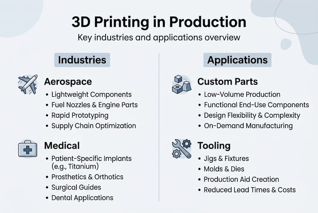
Aerospace and defense use AM for lightweight structural components, ducting, brackets, and heat exchangers. Parts that previously required complex machining or multi-piece assemblies can now be produced as single, optimized geometries.

Medical device manufacturers rely on AM for patient-specific implants, surgical guides, and custom orthotics. The combination of geometric freedom and material traceability is essential for regulatory compliance in this sector.

Automotive teams use industrial AM for end-of-arm tooling, jigs, fixtures, and increasingly for low-volume production parts in electric vehicles and specialty vehicles where traditional tooling costs cannot be justified.

Infographic of 3D printing applications by industry

Electronics and consumer products benefit from AM’s ability to produce complex enclosures, custom connectors, and thermal management components in engineering-grade polymers.

Key advantages that matter for product developers:

  • Geometric freedom: You can print internal channels, lattice structures, and organic geometries that are impossible to machine or mold at any cost.
  • Speed to market: Industrial AM eliminates tooling lead times. Parts that would take 12 to 16 weeks through injection molding can ship in days.
  • Part traceability: Every build is logged with material lot, machine parameters, and operator data, creating a complete quality record.
  • Scalability: Run 5 units or 5,000 units from the same digital file with no retooling cost.

Statistic callout: Powder bed fusion systems like HP MJF produce layers as fine as 80μm while SLS operates around 120μm, delivering isotropic mechanical properties that make these parts suitable for functional, end-use manufacturing without secondary reinforcement.

For a clear view of types of parts possible with industrial AM, the range is broader than most developers expect. And when durability matters, selecting best materials for durability is as critical as selecting the right process.

Our perspective: What engineers miss about manufacturing-grade 3D printing

Most articles about manufacturing-grade 3D printing focus on machine specs, material options, and accuracy numbers. Those things matter, but they miss the deeper issue that experienced teams consistently run into.

The real failure point is almost never the printer. It is the lack of process validation, documentation standards, and quality system integration surrounding the printer. Engineers who move from consumer or mid-tier prototyping equipment to industrial AM often expect a plug-and-play upgrade. What they get instead is a system that demands the same rigor as any other regulated manufacturing process.

Material qualification, environmental controls, build parameter version control, operator training, and output inspection protocols are not optional extras on a manufacturing-grade setup. They are the system. The printer is just one component of it.

Conventional wisdom says, “get a better printer and get better parts.” The truth is, a well-run mid-tier system with disciplined process controls will consistently outperform a premium machine operated without them. Choosing correctly means choosing the right process and the right operational framework around it. Manufacturing-grade is about outcome assurance, not machine capability alone.

Get expert help with manufacturing-grade 3D printing

If you are ready to move your project from concept to production-quality output, the next step is working with a partner who understands both the technology and the engineering requirements behind it.

https://cc3dlabs.com

At CC 3D Labs, we provide manufacturing-grade 3D printing services for product developers and engineers who need reliable, documented results, not just fast prints. Whether you need functional prototypes, low-volume production runs, or on-demand custom parts, we bring process expertise and quality focus to every order. Explore parts you can print with industrial-grade filament systems and request a free estimate to get your project moving with confidence.

Frequently asked questions

What makes a 3D printer manufacturing-grade?

Manufacturing-grade 3D printers are designed for production environments, offering high repeatability, controlled material usage, in-process monitoring, and factory integration. They are built to document and validate every aspect of the production process, not just produce individual parts.

Which 3D printing method is best for low-volume polymer production?

Powder Bed Fusion technologies like SLS and HP Multi Jet Fusion are preferred for low-volume polymer manufacturing because they produce isotropic parts without support structures, which improves consistency and reduces post-processing.

Can manufacturing-grade 3D printers be used for end-use functional parts?

Yes. Systems like HP MJF and SLS produce isotropic end-use parts with fine layer resolution and material traceability, making them fully suitable for functional, production-intent components in aerospace, medical, and automotive applications.

Why is print accuracy important in manufacturing-grade systems?

Precise, validated accuracy ensures that parts meet dimensional tolerances consistently across an entire batch. The Stratasys F900 achieves ±0.089mm accuracy at a 95% yield rate, which is the kind of documented repeatability that production engineering actually requires.

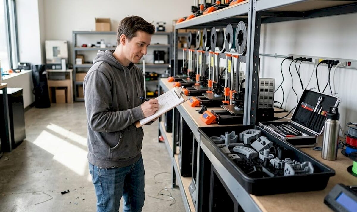
Technician inspects batch 3D printed parts

Batch 3D Printing: A Practical How-To Guide for 2026


TL;DR:

  • 3D printing is cost-effective for batch sizes up to 500 units, especially for complex geometries.
  • Preparing detailed design verification, proper material selection, and meticulous post-processing are essential for quality.
  • Scaling requires validation, central management, and risk mitigation through smaller sub-runs and redundancy.

Traditional manufacturing hits a wall when you need 50, 200, or 500 parts fast. Tooling costs for injection molding can exceed tens of thousands of dollars before a single part ships, and CNC machining queues stretch weeks when you need agility. 3D printing flips that equation, letting you run functional batches without custom tooling, long lead times, or minimum order commitments. This guide walks you through every stage of batch production with 3D printing, from early design decisions to post-processing and scaling, so you can move faster, waste less, and produce parts that actually perform.

Table of Contents

Key Takeaways

Point Details
Best for small to medium runs 3D printing shines in batch production for units below 1000, avoiding costly tooling.
Preparation is critical Successful batches depend on careful design, material choice, and spacing strategies.
SLS and MJF for durability These methods offer superior consistency and strength over FDM, making them ideal for functional parts.
Scale with caution Split large jobs into safer batches and document processes for better control and repeatability.

Understanding batch production in 3D printing

Batch production means manufacturing a defined quantity of parts in one or more coordinated print runs, rather than printing one-off or running continuous mass production. In the 3D printing context, a batch can be as small as 10 units or as large as several hundred, all produced with consistent settings, materials, and quality checks.

The question most engineers face is: when does 3D printing beat traditional manufacturing for batch work? The answer depends on volume, complexity, and tooling cost. 3D printing is cost-effective under 500 units, especially for complex geometries that would require expensive molds or multi-axis CNC fixturing. Above 1,000 units, injection molding typically wins on per-part cost, but you lose the flexibility to iterate designs mid-run.

For low-volume manufacturing tips that keep costs under control, the key advantage of 3D printing is eliminating setup costs entirely. No mold, no jig, no fixture. You change a file and reprint.

When 3D printing batch production makes sense:

  • Runs of 10 to 500 units with design iteration expected
  • Complex internal geometries that molds cannot produce
  • Tight launch timelines with no room for tooling lead times
  • Custom or personalized variants within the same batch
  • Bridge production while waiting for injection mold tooling

Here is a quick comparison to frame your decision:

Factor 3D printing Injection molding CNC machining
Setup cost Near zero $5,000 to $50,000+ Medium to high
Best volume Under 500 units Over 1,000 units 1 to 200 units
Design changes Instant file update Mold rework required Re-program needed
Geometry complexity Excellent Limited by draft angles Limited by tool access
Lead time Hours to days Weeks to months Days to weeks

Hybrid workflows, combining additive manufacturing with light CNC finishing, often deliver the best results for functional batches needing tight tolerances. Knowing which 3D printing type to choose for your part requirements is the first real decision.

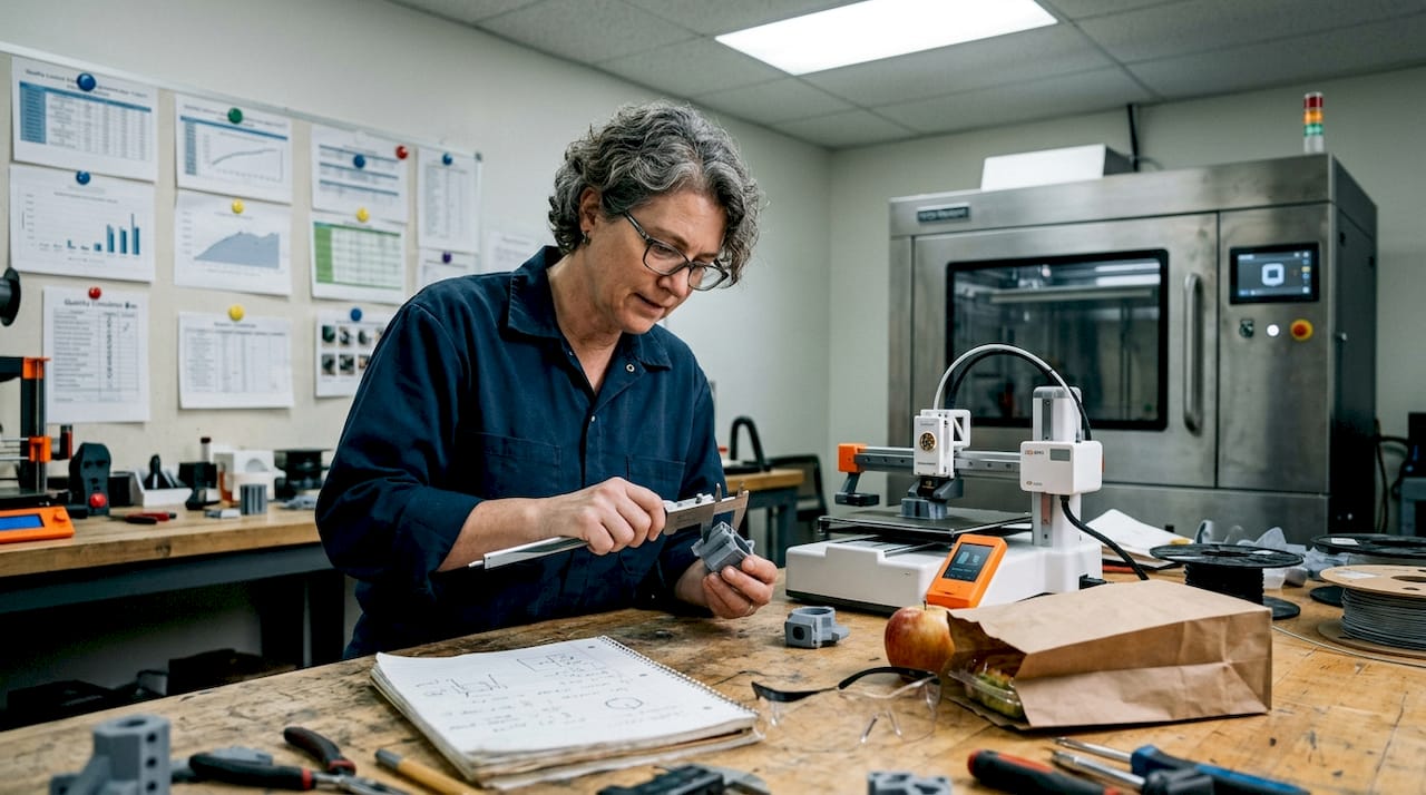
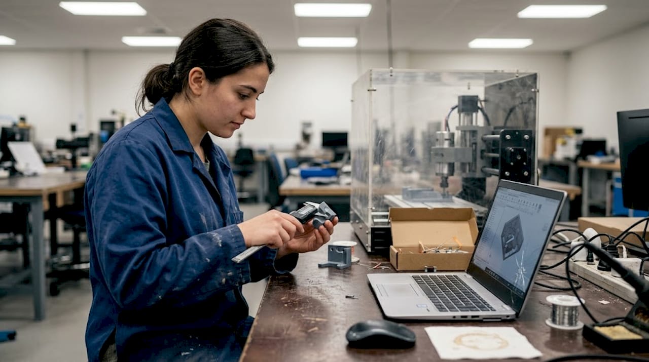
Engineer measuring 3D printed part at bench

Mapping out your batch: Preparation essentials

Understanding the benefits is only useful if you prepare correctly. Here’s what you need for a smooth batch production run.

Before you start printing, your design files and production plan need to be solid. A single upstream error, like a wall thickness below the printer’s reliable minimum, can ruin an entire tray of parts. Designing reliable 3D prints starts with checking tolerances, adding consistent wall thicknesses, and minimizing overhangs that require dense support structures.

Pre-batch preparation checklist:

  • Verify all STL or 3MF files are watertight with no mesh errors
  • Set tolerances to account for your material’s shrinkage rate
  • Orient parts to minimize support material and maximize layer strength
  • Choose material based on mechanical, thermal, and surface finish requirements
  • Confirm build volume fits your batch without overcrowding
  • Test one or two parts before committing the full batch

Material selection is often underestimated. PLA works for display prototypes but fails under heat or load. PETG balances ease of printing with decent mechanical properties. Nylon and PA12 powders suit functional end-use parts. Your post-processing plan also influences material choice, since some materials sand, dye, or machine better than others.

For FDM batch runs, sequential printing over simultaneous is more reliable, especially on multi-nozzle or single-head machines. Keep 5 to 10mm spacing between parts, enable Z-hop at 0.2 to 0.4mm to avoid knocking parts over, and turn on combing to minimize stringing across the build plate. For powder-bed processes like SLS, the powder acts as a self-supporting medium, so you can stack and nest parts freely in the Z direction.

Setting FDM batch SLS/MJF batch
Part spacing 5 to 10mm 2 to 5mm
Support strategy Minimized but required Not required
Z-hop 0.2 to 0.4mm Not applicable
Nesting 2D build plate Full 3D volume

If you use 3D scanning to verify existing parts or reverse-engineer components, integrating high quality 3D scan data into your pre-production workflow reduces dimensional errors before the first layer prints.

Pro Tip: Design every part in a batch to share the same orientation on the build plate. Consistent orientation means consistent layer lines, consistent strength, and consistent surface finish across every unit.

Executing the batch production process: Step-by-step guide

Prepping your batch is only half the equation. Now, let’s walk through a reliable execution plan.

  1. Slice and nest your files. Use your slicer’s auto-arrange or manual layout to maximize density without crowding. Review the 3D preview for collisions or thin unsupported sections.
  2. Validate machine state. Check bed adhesion surfaces, nozzle condition, filament moisture content for FDM, or powder age for SLS/MJF. A contaminated bed ruins the entire tray.
  3. Run a single-unit test print. Before committing 200 parts, confirm one unit meets dimensional and visual specs. This step saves hours.
  4. Start the batch and monitor early layers. The first three to five layers predict 90% of batch failures. Stay close or use a camera feed to catch adhesion issues early.
  5. Log runtime parameters. Record temperature, humidity, print speed, and any deviations. This data is your diagnostic tool for the next run.
  6. Handle mid-run adjustments carefully. Some slicers and firmware allow live flow rate or temperature tweaks. If you adjust, document it immediately.
  7. Remove and label each batch tray. Traceability matters. Label each tray with date, material lot, and settings version before post-processing begins.

“MJF PA12 tensile strength reaches approximately 46 MPa and withstands 100,000 cycles with under 16% stiffness loss, while SLS offers better batch-to-batch reproducibility. FDM remains limited by layer anisotropy and delamination risk for functional batch parts.”

For teams printing quality prototypes alongside functional parts, keeping separate print queues by material and purpose prevents cross-contamination of settings and priorities.

Pro Tip: Log every print run in a simple spreadsheet: date, machine, material lot, settings file version, and any anomalies. When a defect appears in batch 47, you will know exactly what changed from batch 46.

For teams scaling to print farm operations, 3D printing on demand with distributed printers requires centralized file management and consistent firmware versions across all machines to avoid output variation.

Post-processing and quality verification: What to check

You’ve completed your batch run, but production isn’t finished until you ensure every part meets your standard.

Post-processing is where batch efficiency either compounds or collapses. Rush it, and defects slip into the supply chain. Over-engineer it, and you lose the cost advantage of additive manufacturing entirely. The goal is a structured, repeatable QA process scaled to your batch size and part function.

Core post-processing steps by part type:

  • Support removal: Remove carefully with flush cutters or media blasting for SLS/MJF parts. Inspect support interfaces for surface damage.
  • Surface finishing: Sand, bead blast, or vapor smooth depending on cosmetic requirements and material.
  • Dimensional check: Measure critical features with calipers, CMM, or go/no-go gauges. Focus on mating surfaces, bores, and thread engagement zones.
  • Mechanical inspection: Flex-test clips, torque-test fastener points, or pull-test adhesive joints where functional performance is critical.
  • Cosmetic review: Check for layer delamination, warping, color inconsistency, or surface voids under diffuse lighting.

For production batches of 300 to 800 units in industrial device applications, MJF suits mid-volume functional runs while SLS delivers tighter batch-to-batch reproducibility. FDM is a real risk for parts that see mechanical stress or cyclic loading.

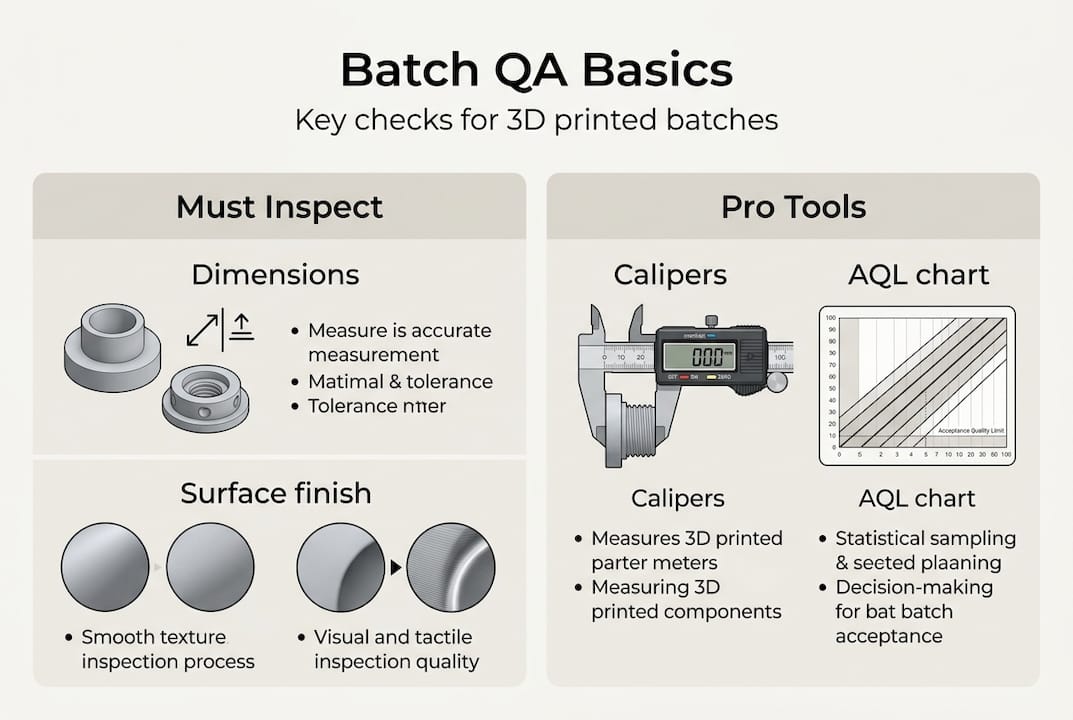
Sampling strategy matters. You do not need to inspect every unit in a 500-part batch. Use AQL (Acceptable Quality Level) sampling tables to select a statistically valid sample size. For critical functional parts, inspect 100%.

Infographic showing batch 3D print QA basics

Printer type Typical post-processing QA priority
FDM Support removal, sanding Delamination, warping
SLS Powder removal, bead blast Dimensional accuracy
MJF Powder removal, dyeing Surface consistency
Resin UV cure, support removal Brittleness, warping

For insight into functional part fabrication requirements across different industries, matching your QA process to the part’s end use is the fastest way to keep costs reasonable without cutting corners.

Scaling up and optimizing your batch production workflow

After validating one batch, you may need to ramp up production. Here’s how to scale efficiently without sacrificing quality.

  1. Validate before scaling. Run two or three small batches with full QA before increasing volume. Undetected issues multiply fast at scale.
  2. Introduce print farms gradually. Add machines in pairs, not all at once. Validate output from each new machine against your baseline before routing production jobs to it.
  3. Centralize file and settings management. Use a version-controlled repository for all print profiles. A rogue settings file on one machine can corrupt an entire production run.
  4. Automate where the ROI is clear. Automated bed leveling, filament runout sensors, and camera monitoring pay back quickly. Full robotic part removal is worth evaluating for very high-volume FDM farms.
  5. Build redundancy into your schedule. Plan for one machine to be down at any time. If your schedule cannot absorb one printer being offline, you are understaffed on capacity.

Breaking mega-batches into smaller sub-runs reduces catastrophic failure risk and makes QA more manageable. If one sub-run fails, you lose a fraction of your day, not your entire production week. MJF and SLS isotropic properties make them the natural choice for functional batch scaling, but secondary machining remains necessary for features requiring tolerances tighter than ±0.2mm.

For teams evaluating custom batch printing jobs, the decision between in-house scaling and outsourcing often comes down to utilization rate. Owning printers makes sense above 60 to 70% utilization. Below that, a service bureau is almost always more cost-effective. Staying current on 3D printing trends shaping manufacturing helps you time capital investments in new equipment wisely.

Pro Tip: Split any batch larger than 100 units into at least two separate print runs on separate machines. This gives you a live comparison of output consistency and a safety net if one machine develops a problem mid-run.

A practical perspective: What most guides miss about batch 3D printing

Most batch production tutorials focus on filling the build volume. Pack the tray, maximize machine time, reduce cost per part. We have seen that logic backfire more than once. When a tray of 80 parts fails at hour 14 because one part warped into the print head, you lose all 80 parts and the machine time. Two trays of 40 parts, run sequentially, would have saved at least half the output.

The real discipline in batch 3D printing is not optimization. It is risk management. Experienced production teams prioritize traceability, redundancy, and process documentation over raw throughput. They know which failures repeat and why, because they logged the data from the last 30 runs.

Post-processing and QA also take longer than engineers typically budget. A 10-hour print run can generate 6 to 8 hours of support removal, inspection, and finishing work. That hidden labor cost often makes on-demand custom parts from a service provider more economical than in-house production for periodic batch needs.

Hybrid workflows, additive for complex geometry and traditional machining for tight tolerances, consistently outperform pure additive in SME environments. The engineers who figure that out early stop chasing tolerances the printer cannot reliably hold and start designing around the process instead.

Ready to streamline your batch production?

Armed with these strategies, you may be ready to print smarter, not harder. If you want to put these best practices into action even faster, here’s where to start.

https://cc3dlabs.com

At CC 3D Labs, we specialize in exactly this kind of work: prototypes, functional parts, and low- to mid-volume 3D printing services for product developers and manufacturers who need reliable output without the overhead of in-house print farms. Whether you want to explore what 3D printing can do for your specific parts or you are ready to place an on-demand batch printing order, our team near Philadelphia is set up to support your production goals with fast turnaround and real quality control.

Frequently asked questions

What is batch production in 3D printing?

Batch production in 3D printing means manufacturing multiple identical or varied parts in one or more print runs, optimizing efficiency and costs without needing complex tooling. It is cost-effective for runs under 500 units, especially for complex geometries.

How do I avoid failed parts during batch 3D printing?

Split large jobs into smaller batches, use print farms for redundancy, and log each print’s settings to catch recurring errors early. Breaking mega-batches into sub-runs limits how much output you lose when something goes wrong.

Which 3D printing method is best for functional parts in batches?

SLS and MJF offer the best strength and batch consistency for functional parts. MJF PA12 reaches approximately 46 MPa tensile strength and handles high-cycle loading well, while FDM is less reliable for stressed or high-cycle use.

Is 3D printing suitable for high-volume manufacturing?

3D printing is best for batches under 1,000 units. For higher volumes, injection molding outperforms 3D printing on per-part cost, though tooling investment and lead time are significantly higher.