

TL;DR:
- A structured prototyping workflow helps teams transform initial ideas into validated parts efficiently and with fewer revisions.
- Focusing on specific questions early avoids costly mistakes and speeds up the path to manufacturing readiness.
The workflow for custom part prototyping is a systematic process that transforms initial design concepts into validated physical parts through iterative testing and refinement. Product developers who follow a structured sequence, from concept sketching through CAD modeling in tools like Fusion 360 or SolidWorks, to fabrication using FDM, SLA, or CNC machining, consistently reach manufacturing-ready designs faster and with fewer costly revisions. The full design-to-manufacturing cycle typically spans 3–6 months, with the prototyping and testing phase alone running 4–8 weeks. Getting that sequence right from the start is what separates teams that ship on time from those stuck in late-stage redesign loops.
What are the prerequisites for a custom part prototyping workflow?
A solid prototyping workflow starts before any CAD file is opened. You need three things in place: clear design goals, documented user requirements, and at least rough concept sketches that define form, function, and constraints. Skipping this step is the single most expensive mistake in custom part development.
Choosing the right software
The two dominant tools for custom part design are Fusion 360 and SolidWorks. Fusion 360 suits smaller teams and startups because it runs in the cloud and costs less per seat. SolidWorks is the standard in larger manufacturing environments where assembly modeling and simulation matter most. Both export STL and STEP files that feed directly into 3D printing or CNC workflows.
Selecting your prototyping technology
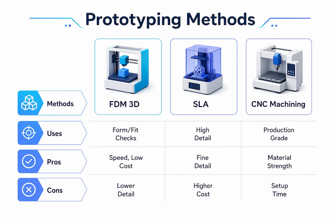
Common prototyping methods include FDM 3D printing, SLA, SLS, CNC machining with production-grade materials, and silicone molding for short runs. Each serves a different purpose depending on fidelity, material, and budget.
| Method | Best use case | Pros | Cons |
|---|---|---|---|
| FDM 3D printing | Form and fit checks, early concepts | Low cost, fast turnaround | Lower surface finish |
| SLA 3D printing | Visual models, fine detail | High resolution | Brittle, limited materials |
| SLS 3D printing | Functional parts, complex geometry | Strong, no support needed | Higher cost per part |
| CNC machining | Functional metal or plastic parts | Production-grade accuracy | Slower, more expensive setup |
| Silicone molding | Short-run flexible parts | Good material fidelity | Tooling time required |
Pro Tip: Match fidelity to your current test goal. A rough FDM print answers geometry questions just as well as an SLA model at a fraction of the cost. Save high-fidelity methods for functional validation.
What are the step-by-step stages of the prototyping workflow?
Rapid prototyping is an iterative cycle of prototype, test, and refine designed to validate ideas quickly before full-scale development. The key is treating each stage as a question to answer, not a deliverable to complete.
-
Define learning goals (1–3 days). Write down the specific questions this prototype must answer. “Does the mounting bracket clear the housing?” is a testable question. “Is this a good design?” is not.
-
Create low-fidelity concepts (2–4 days). Sketch or model rough geometry in Fusion 360 or SolidWorks. At this stage, speed matters more than accuracy. Paper mockups and foam models are valid tools.
-
Build the first prototype (3–7 days). Fabricate using the method that matches your current fidelity need. FDM printing works for most early-stage form and fit checks. The design-to-prototype workflow from file to physical part can run in under 24 hours with the right setup.
-
Test with targeted users or stakeholders (1–7 days). Testing with just 5 users uncovers about 85% of usability problems. That number means you do not need a large test group to get meaningful feedback on a physical part.
-
Analyze feedback and document findings (1–2 days). Log every issue by severity. Separate cosmetic problems from functional failures. Functional failures block the next stage. Cosmetic issues can wait.
-
Iterate and refine (repeat 2–4 cycles). Iterative prototyping typically requires 2–4 cycles to stabilize major design assumptions. Each cycle should be faster than the last because your questions get more specific.
-
Finalize for manufacturing prep (2–4 weeks). Once the design passes functional testing, update the CAD model with production tolerances, material callouts, and GD&T annotations. This is the handoff package your manufacturer needs.
Pro Tip: Never skip from a first print straight to manufacturing prep. The cost of one extra iteration cycle is always lower than the cost of a tooling change after production starts.
How do efficient prototyping techniques cut cost and time?
Rapid 3D printing technologies reduce lead time and early validation costs compared to traditional tooling methods. The gap is significant. A CNC-machined aluminum prototype can take two weeks and cost several hundred dollars per part. An FDM print of the same geometry takes hours and costs a few dollars in filament.
The table below shows where each approach wins:
| Approach | Typical lead time | Relative cost | Best phase |
|---|---|---|---|
| FDM 3D printing | Hours to 1 day | Very low | Concept and form checks |
| SLA 3D printing | 1–2 days | Low to medium | Visual and detail review |
| CNC machining | 5–14 days | Medium to high | Functional metal validation |
| Traditional injection mold | 4–12 weeks | Very high | Pre-production only |
Working with local prototyping resources cuts turnaround times by 2–3 weeks compared to offshore fabrication. That time saving directly compresses your iteration cycle. Faster iterations mean more design questions answered per month.
Additional techniques that reduce waste in the custom part design process:
- Use the minimum fidelity that answers your current question. Prototyping should focus on answering specific questions, not creating miniature final products.
- Combine methods within a single iteration. Print an FDM shell for geometry, then CNC a metal insert for the load-bearing feature.
- Run parallel prototypes when two design directions are genuinely competitive. Printing both costs less than debating for a week.
- Automate file prep. Tools like Meshmixer and PrusaSlicer reduce the time from CAD export to print start.
- Partner with a local 3D printing service for faster prototype turnaround when your in-house capacity is limited.
What mistakes derail custom part prototyping workflows?
The most common and costly mistake is skipping the discovery phase. Every unit spent on early research saves approximately 100 times that amount in avoided redesigns. Teams that jump straight to CAD without validating user requirements build the wrong thing at full fidelity.
“The best prototyping mindset is to build only what answers current questions. Doing is the best thinking.” — Prototyping: The Complete Guide for UX Designers
Other mistakes that slow or break the prototyping workflow:
- Over-detailing too early. Spending days on surface finish or color accuracy before the geometry is validated wastes time. Lock function before form.
- Ignoring test feedback. Collecting feedback and then not acting on it is worse than not testing. Document every issue and assign it a resolution before the next cycle.
- Wrong material for the test goal. Testing structural load with a brittle SLA print gives misleading results. Match the material to the test you are running.
- Poor iteration tracking. Without version control on your CAD files, teams reintroduce fixed problems in later cycles. Use named file versions or a PDM system like SolidWorks PDM.
- Skipping manufacturing prep review. A prototype that passes functional testing can still fail at the manufacturing stage if tolerances, draft angles, or wall thicknesses are not production-ready.
The transition from prototype to manufacturing-ready design is its own phase. Treat it as such. Assign it dedicated time in your schedule rather than assuming it happens automatically after the last test cycle.
Key Takeaways
A structured workflow for custom part prototyping, built on defined learning goals, matched fidelity, and disciplined iteration, is the most reliable path from concept to manufacturing-ready design.
| Point | Details |
|---|---|
| Define goals before modeling | Write specific testable questions before opening CAD software. |
| Match fidelity to the test | Use FDM for geometry checks and CNC or SLS only for functional validation. |
| Test with a small group | Five users uncover about 85% of usability problems, making large test groups unnecessary. |
| Plan for 2–4 iteration cycles | Most designs require 2–4 cycles to stabilize before manufacturing prep. |
| Never skip discovery | Early research saves roughly 100 times its cost in avoided late-stage redesigns. |
Why I think most teams prototype in the wrong order
Most engineers I talk to treat the first prototype as a proof of concept for their boss, not a tool for answering a specific question. That single mindset shift is responsible for more wasted hours than any software choice or material decision.
The teams that move fastest are the ones who write their test question before they open Fusion 360. They build the minimum geometry that answers that question, test it the same week, and move on. They are not attached to the prototype. They know it will be wrong, and they plan for that.
The evolving capabilities of iterative prototyping methods in 2026 make this mindset easier to execute than ever. FDM printers produce functional parts overnight. 3D scanning closes the loop between physical test results and digital models in minutes. The technology is not the bottleneck. The bottleneck is the habit of treating a prototype like a finished product.
My practical advice: set a hard time limit on each prototype build. If you cannot fabricate and test a prototype in under a week, the scope of that iteration is too large. Break it down. The goal of each cycle is one answered question, not one complete design.
— Justin
Ready to accelerate your prototyping cycle?
Cc3dlabs provides professional 3D printing services for product developers and engineers near Philadelphia and ships nationally. Whether you need a quick FDM form check or a functional filament part for load testing, Cc3dlabs delivers accurate parts with fast turnaround times.

The team at Cc3dlabs supports your full custom part design process, from file review and design feedback to multi-material printing and batch production. If you want to see what is possible before committing, explore the on-demand prototyping options or request a free online estimate directly from the website.
FAQ
What is the typical timeline for custom part prototyping?
The full process from concept to manufacturing prep takes 3–6 months. The prototyping and testing phase specifically runs 4–8 weeks depending on complexity and iteration count.
How many prototype iterations are normally needed?
Most designs require 2–4 iteration cycles to stabilize major assumptions. Each cycle should answer a specific design question before moving to the next.
What is the best 3D printing method for early-stage prototypes?
FDM printing is the best starting point for most early-stage form and fit checks. It is fast, low cost, and produces parts within hours, making it ideal for rapid iteration.
How many users do I need to test a prototype?
Testing with 5 users uncovers approximately 85% of usability problems. You do not need a large group to get reliable feedback on a physical prototype.
When should I switch from prototyping to manufacturing prep?
Switch to manufacturing prep after the design passes functional testing and all critical design questions are answered. Update the CAD model with production tolerances, material callouts, and GD&T annotations before handing off to your manufacturer.