
TL;DR:
- Many common FDM print failures, such as warping, poor bed adhesion, and anisotropy, arise from thermal and structural issues. Addressing enclosure temperature, bed surface prep, and layer orientation can significantly improve mechanical strength and dimensional stability. Mastering systematic failure analysis with optimized parameters and environment controls distinguishes top engineers from novices.
You pull a prototype off the build plate, measure it against spec, and it’s warped 2mm at the corner. The layer interface cracked under a basic load test. Your material cost is sunk, your timeline is slipping, and the root cause isn’t obvious at first glance. These aren’t rare flukes — they’re predictable failure modes with known solutions. This article walks you through the most persistent mechanical, material, and dimensional challenges in FDM 3D printing, with data-backed strategies and practical settings adjustments you can act on today.
Table of Contents
- Mechanical issues: warping, bed adhesion, and anisotropy
- Strength and material parameter selection: the infill and raster effect
- Dimensional accuracy and stability under thermal cycling
- Expert troubleshooting: fine-tuning, layering, and advanced material tips
- Comparison summary: challenges, impacts, and solutions at a glance
- Beyond the basics: why mastering failure modes separates top engineers
- Professional support and rapid solutions for 3D printing challenges
- Frequently asked questions
Key Takeaways
| Point | Details |
|---|---|
| Tackle warping and adhesion | Control thermal gradients and use enclosures to promote strong first layer and prevent warping. |
| Optimize infill for strength | Select infill and layer parameters based on material and mechanical performance targets. |
| Minimize dimensional drift | Account for thermal cycling and orientation to maintain tight tolerances. |
| Embrace expert tuning | Advanced troubleshooting and layering techniques resolve stubborn quality issues for production parts. |
| Professional help speeds results | When issues persist, specialist 3D printing services can accelerate troubleshooting and delivery. |
Mechanical issues: warping, bed adhesion, and anisotropy
Most print failures trace back to three interconnected problems: warping, poor bed adhesion, and structural weakness from anisotropy. Understanding why each happens is the first step toward eliminating them from your workflow.
Warping and poor bed adhesion are among the most common mechanical challenges in FDM printing, caused by thermal shrinkage and uneven cooling, particularly with ABS and Nylon. When the bottom layers cool faster than the layers above them, differential contraction bends corners upward. This is especially destructive for flat, wide parts where the geometry amplifies every degree of temperature change.
For engineers building functional prototypes, the fix involves more than just spreading glue stick on the print bed. Here are the main factors to address:
- Enclosure temperature control: Keep ambient air around 40 to 50°C for ABS; this slows the cooling rate and reduces stress buildup between layers.
- Bed surface and prep: Use PEI sheets, glass with adhesive, or specialized surfaces matched to your material. Clean with IPA before every run.
- First layer calibration: A first layer squished 10 to 15% below nominal layer height maximizes contact area and adhesion force.
- Brim and raft usage: Wide brims (at least 8mm) physically resist corner lift. Rafts add thermal mass at the base and help equalize temperature.
“For materials prone to warping like ABS and Nylon, enclosing the build volume and tightly calibrating the first layer settings are non-negotiable steps before advanced parameter tuning.” — Recommendations from FDM troubleshooting best practices.
Anisotropy is the other silent killer. Because FDM prints layer by layer, the bond between layers is always the weakest link in the structure. Flexural strength drops 40%+ at a 90° raster angle compared to 0°, with PLA reaching optimal performance at 0° orientation and 50% infill (167 MPa), and ABS peaking at 0° orientation with 75% infill (126 MPa). If your part will see bending loads, the layer stacking direction relative to load direction is not a detail — it’s a design decision.
When working on manufacturing-grade 3D printing projects, these baseline mechanical principles need to be locked in before you start optimizing higher-level parameters.
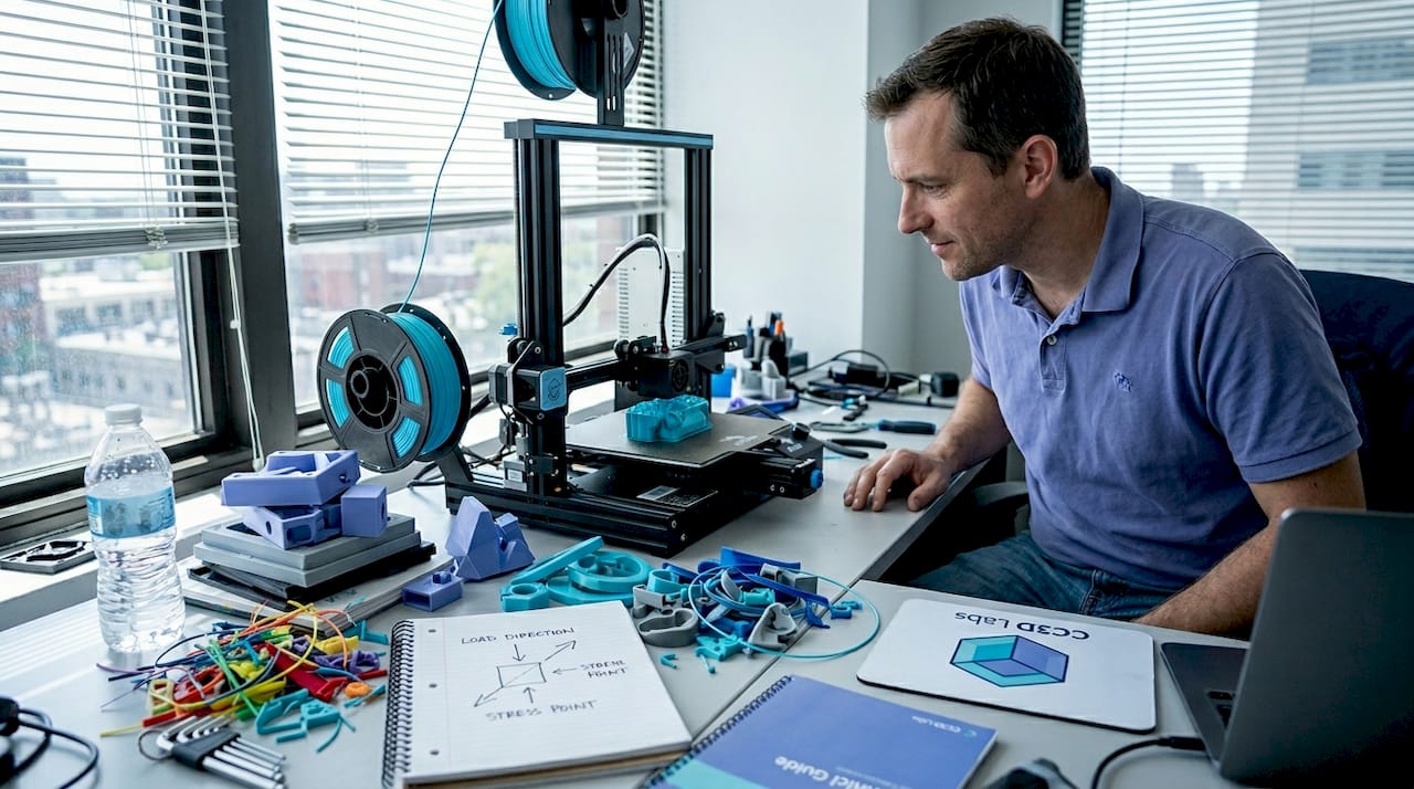
Pro Tip: Before printing any structural prototype, sketch out the primary load direction on paper and orient the model so critical surfaces are parallel to the raster lines. This one decision can roughly double effective flexural strength without changing a single slicer setting.
For anyone newer to these concepts, the filament 3D printing prototyping guide provides a solid foundation before tackling advanced troubleshooting.
Strength and material parameter selection: the infill and raster effect
Once you understand the mechanical failure sources, the next problem is knowing exactly which parameters to adjust for your specific material and application. Infill and raster angle are not just cosmetic settings — they are structural design variables.
Infill density contributes up to 80% of the variation in tensile, compressive, and impact strength, while layer thickness has the biggest influence on hardness and surface roughness. The practical implication: if you need a load-bearing part, infill is your primary lever. If you need a smooth surface for a fit-check prototype, layer thickness takes priority.
Here’s a step-by-step approach to selecting infill and raster angle for common engineering materials:
- Identify the primary load type (tensile, compressive, bending, impact). Each responds differently to infill patterns and density.
- Select material based on operating environment. ABS for moderate heat and chemical exposure, PLA for room-temperature prototypes, Nylon for dynamic or fatigue-heavy applications.
- Set raster angle to 0° as the starting default for maximum strength in the load direction. Reserve 45° or alternating rasters for isotropic requirements.
- Set infill starting point based on the table below, then adjust after a destructive test sample.
- Print a small coupon first. Test before committing material and time to the full part.
| Material | Optimal raster angle | Infill % | Flexural strength | Notes |
|---|---|---|---|---|
| PLA | 0° | 50% | 167 MPa | Best for room-temp structural prototypes |
| ABS | 0° | 75% | 126 MPa | Needs enclosure; warping risk above 100mm |
| Nylon | 0° to 45° | 60 to 75% | Varies | Moisture absorption affects results; dry filament before printing |
| PETG | 45° alternating | 50 to 60% | ~120 MPa | Good layer adhesion; less anisotropy than ABS |
The optimal mechanical parameters for each material matter, but they only deliver results when the print environment (enclosure, bed temp, ambient humidity) supports them. Engineers who treat slicer settings as isolated variables without controlling the full print environment consistently get inconsistent results.
Pro Tip: Run a 3-sample destructive test at your target infill and raster settings before committing to a full production run. A simple bend or pull test on small coupons catches 80% of strength-related surprises before they cost you time and material on full-sized parts.
For a deeper look at how geometry choices interact with these parameters, the resource on designing reliable 3D prints is worth reviewing before finalizing your CAD for print.
Dimensional accuracy and stability under thermal cycling
Strength and adhesion matter at print time, but many engineering parts face an equally serious challenge after they leave the printer: dimensional instability under repeated temperature changes. This is critical for any part used in automotive testing, outdoor hardware, or environments with significant temperature swings.
Dimensional drift under thermal cycling is well-documented: parts can show a height increase of +0.3 mm after just 10 cycles between -20°C and 80°C, with the Z-direction the most affected due to anisotropy between layers. For parts with tight tolerances on height, stacking, or assembly clearance, that 0.3 mm can mean the difference between a fit and a failure.
The Z-direction is vulnerable for a structural reason: the bond between layers is weaker than the base polymer itself. When thermal expansion and contraction work on that interface repeatedly, the cumulative dimensional shift is greater than what you’d see in an injection-molded part made from the same base material.
Here’s a practical checklist to minimize thermal drift in dimensionally critical parts:
- Pre-condition parts before measuring. Let them stabilize at room temperature for at least 2 hours after printing before taking dimensional readings.
- Orient tall features horizontally where tolerance matters. A feature that runs in the XY plane is more dimensionally stable than one that grows in Z.
- Use an enclosure during printing to slow cooling uniformity and reduce residual stress that contributes to post-print drift.
- Anneal parts after printing. For PLA, annealing at 60 to 65°C for 30 to 60 minutes stress-relieves the polymer and improves dimensional stability under subsequent thermal loads.
- Specify material with appropriate thermal coefficient. PETG and ABS both outperform PLA at elevated temperatures; check the glass transition temperature against your expected operating range.
If you’re not familiar with terms like anisotropy, glass transition temperature, or layer adhesion mechanics, the 3D printing terminology resource breaks these down clearly for product developers.
The industry is also moving toward tighter process controls for thermal stability, which you can explore in manufacturing trends in 3D printing to understand where the best practices are headed in 2026.
Expert troubleshooting: fine-tuning, layering, and advanced material tips
With the fundamentals addressed, the final layer of mastery involves diagnosing persistent quality issues that survive basic parameter optimization. These are the problems that show up in advanced prototypes and pre-production runs, and they require a more systematic approach.
The following troubleshooting moves address common high-level flaws:
- Stringing and oozing: Increase retraction distance by 0.5mm increments and reduce travel speed. Dry filament thoroughly before printing, especially with hygroscopic materials like Nylon and PETG.
- Under-extrusion: Check for partial clogs, recalibrate the extruder e-steps, and verify that flow rate matches actual filament diameter at the tip.
- Layer separation: Increase layer temperature in 5°C increments and reduce print speed on perimeter passes. Check that part cooling fans aren’t overwhelming inter-layer bonding on materials like ABS.
- Surface inconsistency on top layers: Increase top layer count from 3 to 5, and verify that infill percentage is high enough to support bridging at the top.
Retraction and flow calibration directly affect part quality in ways that don’t show up in standard strength testing but can catastrophically affect functional performance and appearance. Setting 0° raster and 50 to 75% infill for maximum structural performance is part of this optimization loop.
Advanced layering strategies deserve particular attention for fatigue applications. Multiplane layering, where the model is split and printed in sections oriented on different axes, can meaningfully mitigate Z-direction weakness. It adds complexity, but for parts that will see cyclic loading, it’s a legitimate engineering intervention rather than a workaround.
“Notches and stress concentrations in printed parts reduce fatigue life dramatically. A sharp root radius of just 0.3 mm can reduce epoxy fatigue life by two-thirds, and the same principle applies to layer transitions and internal geometry in FDM parts.”
This is an often-overlooked design point. Engineers frequently focus on infill percentage and raster angle while ignoring sharp internal corners or abrupt geometry transitions that act as stress concentrators during cyclic loading. Rounding internal radii to at least 0.5mm and smoothing layer transition geometry can have more impact than an extra 10% of infill.
For a full walkthrough of how to implement these strategies from print setup through post-processing, the step-by-step guide for quality prints provides actionable detail on each stage.
Comparison summary: challenges, impacts, and solutions at a glance
Use this table as a reference checklist when diagnosing a failed print or planning a new high-stakes prototype.
| Challenge | Symptom | Root cause | Affected property | Proven fix |
|---|---|---|---|---|
| Warping | Lifted corners, base distortion | Uneven cooling, thermal shrinkage | Dimensional accuracy, adhesion | Enclosure, heated bed, brim, first layer calibration |
| Anisotropy | Weak Z-axis fractures | Layer bonding weaker than bulk | Flexural and tensile strength | 0° raster, orientation control, multiplane layering |
| Poor bed adhesion | Part detaches mid-print | Dirty bed, wrong surface, low temp | Print completion, dimensional base | IPA clean, PEI sheet, bed temp match to material |
| Dimensional drift | Tolerance failure after use | Thermal cycling, Z-anisotropy | Assembly fit, tolerance stack-up | Pre-conditioning, annealing, horizontal feature orientation |
| Strength loss | Fracture under expected load | Low infill, wrong raster, wrong material | Load-bearing capacity | Optimize infill, raster angle, run coupon tests |
Each row in this table maps to a root cause you can test and a fix you can implement immediately. The most common mistake is treating these as unrelated problems when they often compound: warping creates residual stress that worsens anisotropy-driven failure under load.
Beyond the basics: why mastering failure modes separates top engineers
Here’s an uncomfortable observation from working with product developers at all levels: the engineers who produce the most reliable printed parts aren’t necessarily using better machines or more exotic materials. They’re the ones who document failures systematically and treat every failed print as diagnostic data.
Textbooks cover the ideal behavior of materials. They rarely cover what happens when ABS prints on a Tuesday in summer at 72% humidity and the first layer adhesion degrades compared to a dry February run. The real world is messy, and default slicer profiles are designed for average conditions, not for your specific geometry, ambient environment, or load requirements.
The engineers who outperform their peers share a common habit: they don’t accept “it just failed” as a root cause. They ask which direction it failed, at what layer, under what load, after how many cycles. That diagnostic precision is what allows rapid iteration instead of repeated guessing.
Chasing new printer releases or exotic filaments without mastering failure analysis is a trap. A well-dialed FDM printer with calibrated settings for manufacturing-grade print quality will consistently outperform a newer machine running on default profiles. Process mastery compounds. Hardware upgrades plateau.
The engineers who build durable, accurate prototypes are the ones who embrace the analytical layer underneath the print settings. That’s not a personality type. It’s a skill you build deliberately, starting with the frameworks in this article.
Professional support and rapid solutions for 3D printing challenges
Persistent print failures can eat weeks of development time when you’re working without access to experienced process feedback. Sometimes the fastest path forward isn’t tuning another setting — it’s getting a professional set of eyes on your geometry, material selection, and print strategy.

At CC 3D Labs, we work directly with product developers and engineers facing exactly the challenges covered in this article. Whether you need rapid turnaround on a tight-tolerance prototype, expert guidance on material and parameter selection, or reliable batch production with verified dimensional accuracy, our team near Philadelphia is set up to deliver. Explore our full 3D printing services, or start with the guide to rapid prototyping to understand how a professional workflow compresses your iteration cycle. For filament-based projects specifically, prototyping with filament printing outlines exactly how we approach each stage from design review to final part delivery.
Frequently asked questions
What causes prints to warp during 3D printing?
Warping is caused by uneven cooling and thermal shrinkage in the base layers, especially with ABS and Nylon. Using an enclosure, a heated bed, and a wide brim effectively reduces warping across most material types.
How does infill density affect part strength in 3D printing?
Infill density contributes up to 80% of the variation in tensile, compressive, and impact strength in FDM printed parts. Higher infill significantly increases load-bearing capacity while layer thickness primarily affects surface hardness and finish.
Why are parts weaker in the Z-direction in FDM 3D printing?
The 40%+ drop in flexural strength at 90° raster angle compared to 0° is a direct result of inter-layer bonding being weaker than the bulk polymer. Orienting the part so critical load paths run in the XY plane is the most effective structural mitigation.
What is the impact of thermal cycling on dimensional accuracy?
Thermal cycling induces measurable dimensional drift, with parts showing up to +0.3 mm height change after 10 cycles between -20°C and 80°C. The Z-direction is most vulnerable due to the anisotropic nature of layer bonding in FDM parts.
How can I improve bed adhesion for better 3D print results?
Clean the print bed with IPA before each run, use a surface matched to your material like PEI for ABS or glass for PLA, and calibrate your first layer height to slightly over-extrude for maximum contact area. Adding an enclosure to stabilize ambient temperature eliminates the thermal differential that causes early delamination.