
TL;DR:
- Filament 3D printing is a versatile and capable rapid prototyping platform, not just a hobbyist tool.
- Proper optimization of materials, design orientation, and parameters can produce strong, functional parts suitable for engineering use.
- Expert support and understanding of process fundamentals can significantly improve print quality and part performance.
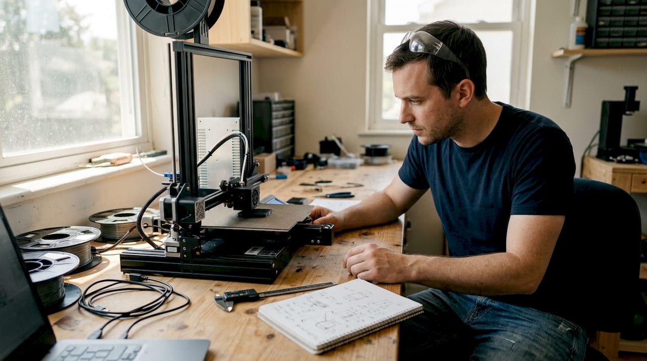
Filament 3D printing gets dismissed as a hobbyist tool far too often. That reputation is outdated and, frankly, costly for any engineer or product developer who buys into it. When you understand the mechanics, material science, and parameter logic behind this process, it becomes one of the most capable rapid prototyping platforms available. This article walks you through how the process works, the complete production workflow, how to choose the right material, how design decisions affect part strength, and how to troubleshoot the most common failures that slow teams down.
Table of Contents
- How filament 3D printing works
- The complete workflow: From digital model to physical part
- Choosing the right filament material: Options and trade-offs
- Design and print parameters: Impact on strength and quality
- Troubleshooting and optimizing: Common pitfalls and solutions
- Why filament 3D printing is underestimated for functional prototyping
- Get expert support for filament 3D printing projects
- Frequently asked questions
Key Takeaways
| Point | Details |
|---|---|
| Layer-by-layer process | Filament 3D printing forms objects from melted thermoplastic extruded and fused in sequential layers. |
| Material selection matters | Different filaments like PLA, ABS, and reinforced composites deliver unique properties for prototyping and production. |
| Design and settings impact strength | Orientation, infill, and printing parameters determine mechanical performance and reliability of parts. |
| Troubleshooting addresses defects | Careful adjustment of temperature, retraction, and moisture solves common printer issues like stringing and warping. |
| FDM is underrated | With thoughtful optimization, filament 3D printing rivals high-end methods for low-volume functional prototypes. |
How filament 3D printing works
At its core, filament 3D printing is a layer-by-layer extrusion process using heated thermoplastic. A spool of solid plastic filament feeds into a heated nozzle, melts, and gets deposited onto a build platform in precise paths. Each deposited layer fuses to the one below it, and the object builds up from the bottom. It sounds simple. The engineering behind it is anything but.
The nozzle diameter controls resolution and throughput. Standard sizes range from 0.2mm for fine detail work up to 0.8mm for fast structural prints. Layer heights typically fall between 0.1mm and 0.3mm, and print speeds run from 30mm/s for precision work to 100mm/s for draft parts. These three variables interact constantly, and tuning them for your specific material and geometry is where real control begins.
Understanding the 3D printing hardware components helps you make better decisions at every stage. The key hardware breaks down like this:
- Extruder: Drives the filament forward. Direct drive extruders sit on the printhead and give better control over flexible materials. Bowden setups place the motor remotely, reducing moving mass for faster speeds.
- Hotend: Melts the filament at a controlled temperature. The heat break separates the melt zone from the cold zone to prevent jamming.
- Build platform: The surface where parts form. Heated beds reduce warping on materials like ABS and PETG.
- Motion system: Controls printhead movement in X, Y, and Z axes. CoreXY and bed-slinger configurations each have speed and accuracy trade-offs.
Key components include the extruder, hotend, build platform, and motion system, and each one influences print quality in ways that compound quickly. A well-calibrated machine with mediocre filament will outperform a premium machine running wet or off-spec material every time.
The FDM extrusion process follows a logical sequence: model creation, slicing into toolpaths, filament extrusion through the nozzle, and layer-by-layer deposition until the part is complete. Each step has failure points. Knowing where they are is the first step to avoiding them.
| Parameter | Typical range | Effect on output |
|---|---|---|
| Nozzle diameter | 0.2 to 0.8mm | Detail vs. speed |
| Layer height | 0.1 to 0.3mm | Surface quality vs. print time |
| Print speed | 30 to 100mm/s | Accuracy vs. throughput |
| Bed temperature | 0 to 110°C | Adhesion and warping control |
With fundamentals established, it’s important to understand the typical workflow for engineers using filament 3D printing.
The complete workflow: From digital model to physical part
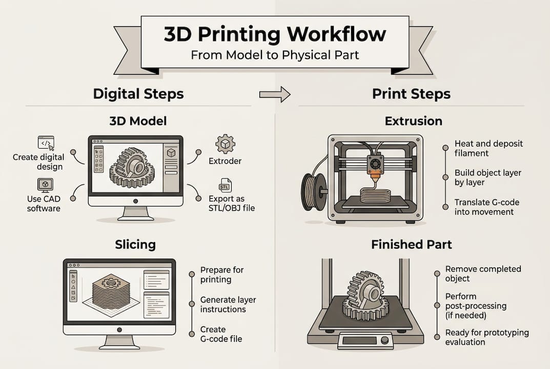
The workflow involves creating a 3D model in STL or OBJ format, slicing it into G-code, feeding filament, melting and extruding, and depositing layers until the part is complete. Each step has real decisions attached to it.
- Model creation: Your part starts in CAD software. SolidWorks, Fusion 360, and Onshape are common choices for engineering-grade work. Export as STL or OBJ. Choosing best CAD file formats for your workflow matters more than most engineers realize, especially when tolerances are tight.
- Slicing: Import your model into slicing software like Cura or PrusaSlicer. The slicer converts geometry into G-code, the machine-readable instruction set that tells the printer exactly where to move, how fast, and at what temperature. This is where you set layer height, infill, supports, and wall count.
- Printer preparation: Load your filament, confirm bed leveling, and set your temperature profiles. A poorly leveled bed is one of the most common causes of first-layer failure. Most modern printers offer automatic mesh bed leveling, but manual verification still matters for critical prints.
- Extrusion and deposition: The printer executes the G-code. The nozzle traces each layer path while depositing molten plastic. Cooling fans solidify each layer before the next one lands on top.
- Post-processing: Remove the part, strip supports, and inspect. Depending on your application, you may sand, prime, or perform secondary machining.
The filament extrusion process details show how tightly each step connects to the next. A poor model creates slicer problems. A bad slice creates print failures. A miscalibrated printer wastes both.
Pro Tip: Always dry hygroscopic filaments like Nylon and PETG before printing. Even a few hours of ambient exposure causes moisture absorption, which shows up as bubbling, rough surfaces, and inconsistent extrusion. A food dehydrator at 65°C for four hours works well. Also tune retraction carefully, typically 0.5 to 6mm depending on your extruder type, to eliminate stringing between features.
With the workflow clear, the choice of filament material is a critical next step for prototyping and production.
Choosing the right filament material: Options and trade-offs
Common materials include PLA, ABS, PETG, TPU, Nylon, PC, and carbon fiber composites, and each one brings a different set of properties to the table. Picking the wrong one for your application costs time and money.
| Material | Strength | Heat resistance | Ease of use | Best for |
|---|---|---|---|---|
| PLA | Moderate | Low (50-60°C) | Very easy | Visual prototypes, concept models |
| ABS | Good | Moderate (80-100°C) | Moderate | Functional housings, enclosures |
| PETG | Good | Moderate (70-80°C) | Easy | Food-safe parts, mechanical use |
| TPU | Flexible | Low to moderate | Moderate | Gaskets, grips, flexible components |
| Nylon | High | High (120°C+) | Difficult | Load-bearing, wear parts |
| PC | Very high | Very high (130°C+) | Difficult | Structural, high-temp applications |
| Carbon fiber composite | Very high | High | Moderate | Lightweight structural parts |
For early-stage concept models, PLA is hard to beat. It’s cheap, easy to print, and produces clean surfaces for stakeholder reviews. The moment your prototype needs to survive real-world loads, temperatures, or chemical exposure, you need to move up the material stack.
For a deeper breakdown, the material comparison guide covers mechanical properties in practical terms. If your parts will live outdoors, the outdoor filament options page is worth reviewing before you commit to a material.
The FDM material guide reinforces that material selection is application-driven, not preference-driven. Key considerations:
- Thermal environment: Will the part see temperatures above 60°C? PLA will fail. PETG, ABS, Nylon, or PC are better choices.
- Mechanical loading: Static display or dynamic stress? Nylon and carbon fiber composites handle cyclic loads far better than PLA.
- Chemical exposure: Oils, solvents, moisture? PETG and Nylon resist many common chemicals.
- Print difficulty: Tight deadline, limited calibration time? Stick to PLA or PETG.
Pro Tip: For functional low-volume parts, carbon fiber reinforced filaments and PC deliver the best strength-to-weight performance. Always dry these materials before printing, as moisture ruins dimensional accuracy and surface quality in high-performance filaments far faster than it does in PLA.
Knowing your material options, the next consideration is how design and print parameters impact the finished part’s properties.
Design and print parameters: Impact on strength and quality
Parts are anisotropic, meaning build orientation and infill pattern critically affect mechanical properties. This is the single most important concept for engineers to internalize before designing for filament printing.
Anisotropy means your part is not equally strong in all directions. Layers bond well within the XY plane but the Z-axis bond between layers is always the weak point. A part loaded perpendicular to its layers will fail earlier than one loaded parallel to them. Design with this in mind from the start.
“70 to 100% infill maximizes mechanical properties. PLA achieves ultimate tensile strength of 38 to 47 MPa at print temperatures of 195 to 220°C.”
Infill pattern and density directly control internal strength. Common options:
- Gyroid: Excellent for isotropic strength and fluid flow applications.
- Triangle: Efficient for flat load distribution.
- Octet: High stiffness, good for structural brackets and fixtures.
- Grid: Fast to print, adequate for non-critical parts.
Orientation is a design decision, not a printer setting. When you design a load-bearing bracket, orient it so the primary load path runs along the XY plane. Avoid thin vertical walls in the Z direction for structural parts.
For parameter tuning, use a design of experiments (DOE) approach. Vary one parameter at a time: temperature, speed, cooling, and wall count. Print small test coupons before committing to a full run. This saves material and time.
Choosing the right print type for prototypes depends heavily on these parameters. For parts that need to meet real performance specs, engineering-grade prints with optimized settings are the right call. The anisotropy and infill effects on finished parts are well-documented and should drive your parameter choices.
Finally, understanding common printing challenges and how to resolve them is critical for achieving consistent results.
Troubleshooting and optimizing: Common pitfalls and solutions
Stringing, oozing, diameter variance, humidity, and warping are the most common failure modes in filament printing. Each has a clear cause and a clear fix.
- Stringing and oozing: Caused by excess heat or insufficient retraction. Reduce print temperature by 5 to 10°C and increase retraction distance. Travel speed also matters. Faster travel gives the molten plastic less time to drip.
- Under-extrusion: Usually a partial clog, worn drive gear, or incorrect flow rate. Check filament diameter. Ideal tolerance is ±0.02mm. A filament that measures 1.78mm instead of 1.75mm will cause consistent under-extrusion.
- Over-extrusion: Too much material per move. Calibrate your extruder steps-per-mm and run a flow rate test before printing functional parts.
- Warping on large parts: Heated bed, enclosure, and brim settings all help. ABS and Nylon are the worst offenders. A 100 to 110°C bed and enclosed build chamber reduce warping significantly.
- Moisture-related defects: Bubbling, rough surfaces, and weak layers all point to wet filament. Dry your spools before every critical print run.
For stringing solutions, the fix is almost always a combination of temperature reduction and retraction tuning. For on-demand print troubleshooting, working with an experienced service provider eliminates most of these variables before your parts even start printing.
Pro Tip: Small parameter tweaks solve most problems. A 5 to 10°C temperature drop, a retraction adjustment of 0.5 to 6mm, and a travel speed increase of 20mm/s will resolve the majority of stringing and surface quality issues without requiring a full recalibration.
Why filament 3D printing is underestimated for functional prototyping
Most engineers who write off filament printing for functional work have never actually optimized it. They ran a part at default settings, saw weak layer lines, and moved on. That’s a methodology failure, not a technology failure.
FDM is best for low-volume functional prototypes when strength is prioritized through deliberate design choices. The teams that get real value from filament printing treat it like any other manufacturing process: they design for its constraints and exploit its strengths.
The biggest missed opportunity is ignoring anisotropy at the design stage. When you orient parts correctly, use reinforced filaments, and dial in wall thickness and infill, the results surprise people. We have seen carbon fiber PETG parts replace machined aluminum fixtures in low-load applications. That is not a fluke. It is the result of treating parameter optimization seriously.
Rapid iteration is where filament printing genuinely has no peer at the early hardware stage. You can go from a revised CAD file to a testable part in hours. No tooling, no lead time, no minimum order. For print terminology for engineers who are new to this space, understanding the vocabulary of the process is the first step toward using it strategically.
Pro Tip: Incorporate thicker perimeter walls (3 to 5 shells), use gyroid or octet infill at 40 to 60%, and always dry your filament. Those three changes alone can double the effective strength of a printed functional prototype.
Get expert support for filament 3D printing projects
Filament 3D printing rewards knowledge and punishes guesswork. If you are working on a prototype that needs to perform, not just look good, the material, parameter, and design decisions covered here are exactly where professional support adds the most value.

At CC 3D Labs, we work with product developers and engineers on professional 3D printing services that go beyond basic output. From material selection to parameter optimization and production-ready tolerances, we handle the variables so you can focus on your design. Whether you are exploring parts you can print for the first time or need reliable on-demand prototypes for an active development cycle, we are ready to help. Reach out for a free estimate and let’s build something that works.
Frequently asked questions
What is the difference between FDM and FFF in filament 3D printing?
FDM and FFF are essentially the same material extrusion process but with different names. FDM is a trademarked term, while FFF (Fused Filament Fabrication) is the open-source generic version used across the broader community.
How do I avoid stringing in filament 3D prints?
Reduce printing temperature, increase retraction distance, and raise travel speed. Retraction of 0.5 to 6mm combined with a 5 to 10°C temperature drop resolves most stringing issues without affecting overall print quality.
Which filament material is best for low-volume functional prototypes?
Carbon fiber composites and PC deliver the highest strength for demanding applications. PLA works for non-structural prototypes, but reinforced filaments are the right choice when parts need to survive real-world loading.
Why are 3D printed parts weaker in the Z direction?
Parts are stronger in XY than in Z because inter-layer bonding is mechanically weaker than in-plane deposition. Design your parts so primary loads run along the XY build plane to avoid inter-layer failure.
How do I store filament to prevent humidity issues?
Store filament in airtight containers with desiccant packs. Humidity affects filament flow and causes bubbling, rough surfaces, and weak layer bonding, so dry box storage is essential for hygroscopic materials like Nylon, PETG, and PC.
Recommended
- Choose the right 3D printing type for prototypes & production
- What can a 3D printer make? Prototypes to functional parts
- Find the best 3D print job for custom prototypes & parts
- Defining 3D printing terminology for product developers
- Beginner’s Guide to DTF Printing: Success for Apparel Creators – Transfer Kingz