
TL;DR:
- PETG outperforms ABS in impact resistance with 15-20% higher impact cycles before failure.
- Material choice depends on operating environment, with PETG suitable for impact and chemical exposure.
- Proper print parameters and part design are critical to ensure functional part reliability, not just material selection.
Most engineers assume ABS is the toughest material for functional 3D printed parts. That assumption has cost real projects real money. Recent bracket testing found that PETG survived 15-20% more impact cycles than ABS before failure, which forces a rethink of the default material hierarchy. Choosing between PLA, PETG, and ABS is not just a spec-sheet exercise. It involves understanding how each material behaves under real stress, how print settings amplify or undermine those properties, and how your part geometry interacts with the material’s natural weaknesses. This article gives you a practical, data-backed framework to make that call with confidence.
Table of Contents
- Understanding PLA, PETG, and ABS: Properties and applications
- Mechanical performance: Real-world testing and data
- Print processing and part design: From parameters to practicality
- Choosing the right material for your functional part
- A manufacturer’s perspective: What most comparisons miss
- Get expert help with functional 3D printing
- Frequently asked questions
Key Takeaways
| Point | Details |
|---|---|
| PETG excels in impact | PETG outperforms ABS and PLA in real-world impact tests for brackets and functional parts. |
| Design affects strength | Print settings like infill and orientation matter as much as material choice for part durability. |
| No universal best | Optimal material depends on use case, required heat resistance, and specific application demands. |
| Expert guidance helps | Consulting material and process experts prevents costly failures in functional 3D prints. |
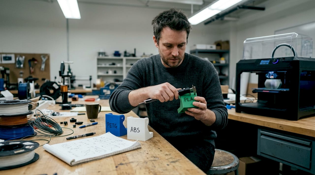
Understanding PLA, PETG, and ABS: Properties and applications
Before running any stress test, you need a clear picture of what each material actually offers. Knowing the 3D printing terms that describe material behavior will help you read data sheets and supplier claims more critically.
PLA (Polylactic Acid) is the easiest of the three to print. It runs at lower temperatures, sticks well to most build surfaces, and produces minimal warping. Tensile strength is competitive, often reaching 50-65 MPa in solid form. The catch is brittleness: PLA fails suddenly under impact rather than deforming, and its heat deflection temperature sits around 50-60°C, which rules it out for any part near a heat source.
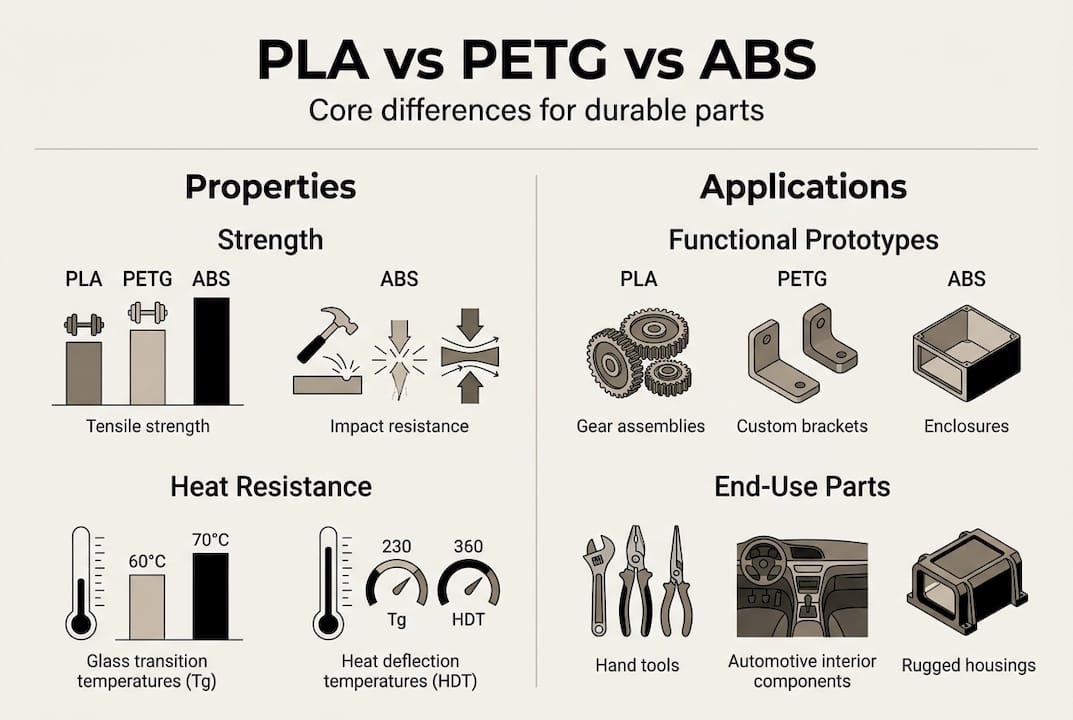
PETG (Polyethylene Terephthalate Glycol) sits in a practical middle ground. It is tougher and more ductile than PLA, offers solid chemical resistance to many common solvents, and handles temperatures up to roughly 80°C. It bonds well between layers, which reduces the anisotropy risk that plagues many FDM parts. Print settings are a bit more demanding than PLA but far more forgiving than ABS.
ABS (Acrylonitrile Butadiene Styrene) brings the highest heat resistance of the three, with a deflection temperature around 100°C, and it machines and post-processes well. The tradeoffs are real: ABS requires an enclosure to prevent warping, emits fumes that need ventilation, and shows weaker interlayer adhesion than PETG under certain loading conditions.
Here is a quick reference for the three materials:
| Property | PLA | PETG | ABS |
|---|---|---|---|
| Tensile strength (solid) | 50-65 MPa | 45-55 MPa | 40-50 MPa |
| Heat deflection temp | ~55°C | ~80°C | ~100°C |
| Impact resistance | Low | High | Moderate |
| Print difficulty | Easy | Moderate | Hard |
| Chemical resistance | Low | Moderate | Moderate |
| Cost | Low | Moderate | Moderate |
Common applications break down like this:
- PLA: Concept models, low-stress fixtures, display parts, short-run jigs
- PETG: Functional brackets, fluid-contact parts, snap-fit assemblies, enclosures
- ABS: Under-hood automotive components, electrical housings, parts requiring acetone smoothing
One critical point that many teams overlook: strength in FDM depends heavily on print parameters like infill and layer orientation, not just the raw material. Solid material tensile values are a starting point, not a guarantee. Following material selection best practices before committing to a filament can prevent expensive redesigns later.
Pro Tip: Before finalizing your material, ask whether your part will face chemical exposure or sustained heat. If yes, PLA is almost certainly off the table, and the real decision is between PETG and ABS based on your temperature ceiling.
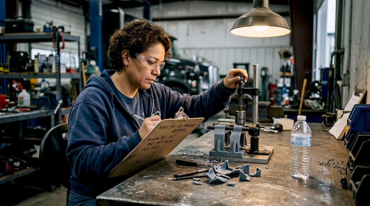
Mechanical performance: Real-world testing and data
With a clearer understanding of the base properties, it is important to examine how these materials actually behave in real functional stress scenarios.
The most telling data point for product developers is impact performance. In controlled bracket testing, PETG outperformed ABS by 15-20% in impact cycle counts before failure. That is not a marginal difference. For parts that experience repeated loading, vibration, or drop risk, PETG is the more reliable choice despite ABS’s reputation.
Infill geometry matters more than most teams realize. Hexagonal infill at 30% density produced a PETG tensile strength of 18.54 MPa in standardized testing, outperforming rectilinear and triangular patterns at the same density. That means you can hit stronger results without increasing material use, simply by changing the infill pattern in your slicer.
Here is how the three materials compare in key functional metrics:
| Test condition | PLA | PETG | ABS |
|---|---|---|---|
| Impact resistance | Brittle, sudden failure | High, ductile deformation | Moderate |
| Layer adhesion | Good | Excellent | Fair to good |
| Warping risk | Very low | Low | High |
| Post-failure behavior | Shatters | Deforms | Cracks/splits |
| Thermal cycling stability | Poor | Good | Good |
PLA’s failure mode is the most dangerous for functional parts. It does not warn you. It holds load until it does not, then fractures cleanly. For printed functional parts that carry real mechanical loads, that sudden failure mode is a liability.
To maximize performance from whichever material you choose, follow this process:
- Set infill to hexagonal or gyroid pattern for load-bearing parts
- Orient the part so the primary stress axis runs parallel to layer lines, not perpendicular
- Increase wall count to at least 3 perimeters for structural sections
- Run a short print at reduced scale to validate failure mode before full production
- Test at actual operating temperature, not just room temperature
Matching these settings to your specific application is exactly the kind of decision that separates a successful run from a costly reprint. Reviewing guidance on matching print jobs to needs before you start slicing is time well spent. For deeper context on industrial prototyping best practices, external resources can fill in the gaps your material data sheet leaves open.
Print processing and part design: From parameters to practicality
Beyond the material’s properties, how you print and design your part is just as critical.
FDM parts are inherently anisotropic. That is not a flaw to work around; it is a reality to design for. As FDM anisotropy research confirms, tensile values from solid material samples do not translate directly to printed parts because layer bonding creates directional strength differences. A part that tests at 50 MPa in the XY plane may perform at 30 MPa or less when loaded in the Z direction.
Key design decisions that directly affect part reliability:
- Wall thickness: Thicker walls reduce the impact of infill anisotropy and improve load distribution. For structural parts, 2.0-3.0 mm minimum wall thickness is a practical baseline.
- Geometry: Avoid sharp internal corners. They concentrate stress and are where layer-bonded parts crack first. Add fillets wherever load paths change direction.
- Orientation: Print the part so the weakest bond direction (Z axis) is not aligned with the primary load. This single decision often matters more than material choice.
- Support strategy: Poorly supported overhangs create surface defects that act as stress risers. Plan your orientation to minimize support contact on functional surfaces.
The most common mistake we see is engineers treating a 3D printed part like a machined one. The geometry looks the same, but the internal structure is completely different. Design for the process, not just the shape.
For teams working from existing CAD files, reviewing optimized CAD workflows for FDM can catch design issues before they become print failures. If you are reverse-engineering an existing part, high quality 3D scans give you accurate geometry to work from rather than guessing at tolerances.
Pro Tip: Always prototype in the exact print orientation you plan to use in production. A part that passes testing in one orientation can fail quickly when reoriented, even with identical settings.
A solid 3D print checklist before each production run catches the parameter drift that causes batch failures.
Choosing the right material for your functional part
Armed with print and performance knowledge, it is time to decide which material best fits your project.
Start with the operating environment. Temperature, chemical exposure, and mechanical loading type are your three filters. Apply them in that order and your material options narrow quickly.
Here is a decision matrix built for functional parts:
| Requirement | Best choice | Why |
|---|---|---|
| Heat above 80°C | ABS | Highest deflection temp |
| Repeated impact loads | PETG | 15-20% more impact cycles vs ABS |
| Chemical exposure | PETG | Better solvent resistance than PLA |
| Low cost prototyping | PLA | Easiest to print, lowest cost |
| Acetone smoothing needed | ABS | Only material that responds to acetone |
| Snap-fit assemblies | PETG | Ductility prevents brittle snap failure |
Use this numbered checklist to streamline your material selection process:
- Define the maximum operating temperature your part will face
- Identify any chemical or fluid contact requirements
- Classify the load type: static, cyclic, or impact
- Determine whether post-processing (smoothing, painting, threading) is required
- Set your cost and lead time constraints
- Cross-reference against the decision matrix above
For on-demand production examples that show how these decisions play out across real part types, reviewing actual project outcomes is more instructive than spec sheets alone. If you are producing prototypes and repair parts under tight timelines, having a clear material brief before you engage a print service cuts revision cycles significantly.
Pro Tip: Factor in post-processing before you lock in your material. ABS is the only one of the three that smooths with acetone vapor, which can matter for sealing surfaces or cosmetic requirements. PETG resists most adhesives, which affects assembly planning.
A manufacturer’s perspective: What most comparisons miss
Most material comparison articles stop at the spec table. That is where the real problems begin.
After working through hundreds of functional part projects, the pattern is clear: material choice causes far fewer failures than print tuning and part design. We have seen PETG parts fail in applications where PLA would have worked fine, simply because the infill was set to rectilinear at 15% and the wall count was two. The material was not the problem. The process was.
The other consistent mistake is ignoring the actual use environment during testing. A bracket that passes a static load test on a workbench will behave very differently when it is mounted in a vibrating enclosure at 70°C. Engineers often validate under ideal conditions and then wonder why field failures happen.
Material selection is a starting point, not a solution. The real work is in aligning material, process, and design to the specific demands of the application. Specialty material projects that push beyond standard filaments make this even more apparent: the process discipline required for high-performance materials exposes every shortcut taken with common ones.
No single material wins every application. The engineers who get consistent results are the ones who treat material, settings, and design as one integrated decision, not three separate checkboxes.
Get expert help with functional 3D printing
Getting material selection right is only the first step. Translating that choice into a reliable, production-ready part requires process expertise that goes well beyond slicer defaults.

At CC 3D Labs, we work with product developers and manufacturing teams to match material, print parameters, and part design to your specific functional requirements. Whether you are evaluating materials for a new bracket design or scaling a prototype to batch production, our team provides hands-on guidance at every stage. Our 3D printing services cover everything from initial material consultation to final part delivery, with fast turnaround and quality you can measure. Explore our on-demand printing solutions to get started with a free estimate today.
Frequently asked questions
Which material is most durable for functional parts: PLA, PETG, or ABS?
PETG typically outlasts both ABS and PLA in impact-heavy applications, with 15-20% more impact cycles before failure in controlled bracket testing. For parts facing repeated loading, PETG is the stronger default choice.
When should I pick PLA over PETG or ABS?
Choose PLA for functional prototypes where ease of printing, low cost, and moderate strength are the priorities and the part will not face sustained heat above 55°C or significant impact loading.
Does infill pattern really affect part strength?
Yes, significantly. FDM strength depends on infill pattern and print orientation, not just material, because printed parts show directional strength differences that solid material values do not capture.
Which material is best for high temperature environments?
ABS offers the highest heat deflection temperature of the three, around 100°C, making it the right choice for parts exposed to sustained elevated temperatures where PETG or PLA would deform.