

TL;DR:
- Design for Manufacturability in 3D printing emphasizes designing parts to align with printer constraints, reducing print time, costs, and failures. Applying early DfAM principles enables part consolidation, improves strength through orientation, and accelerates prototypes, saving costs and time. Most failures result from late-stage design fixes; integrating DfAM from the start produces better products faster and lowers overall manufacturing expenses.
Design for Manufacturability, known in additive manufacturing circles as DfAM, is the practice of shaping a part’s geometry to work with a printer’s physical constraints rather than against them. The benefits of DFM in 3D printing are direct and measurable: faster print cycles, lower material costs, stronger parts, and fewer failed builds. Product developers who apply DfAM principles early catch problems before they become expensive. This article breaks down the top advantages, with specific techniques and data you can act on immediately.
1. How DFM reduces print time and material costs in 3D printing
Applying DFM principles to 3D printing cuts print times by 20–40% and lowers per-part costs by reducing support material and post-processing. That single change, designing geometry that holds itself up, is the highest-leverage move most engineers overlook.
The core technique is self-supporting geometry. Any surface angled greater than 45° from horizontal requires no support structures in FDM printing. Supports add print time, consume filament, and leave surface marks that require finishing work. Eliminating them cuts all three costs at once.
Specific geometry choices that reduce or eliminate supports:
- Chamfers instead of horizontal overhangs. A chamfered edge at 45° prints cleanly. A flat horizontal ledge does not.
- Teardrop holes instead of round holes. Circular holes printed horizontally sag at the top. A teardrop profile with a pointed apex is self-supporting.
- Bridging spans under 5mm. Short horizontal gaps bridge cleanly without supports. Longer spans need either supports or a redesign.
- Angled walls instead of vertical undercuts. Undercuts trap supports in hard-to-reach areas. Angled walls avoid the problem entirely.
Pro Tip: Design overhangs at 50° or steeper rather than exactly 45°. The extra margin accounts for real-world printer variation and reduces the chance of a borderline overhang failing mid-print.
Reducing post-processing effort is just as valuable as cutting print time. Support removal, sanding, and finishing can double the labor cost of a part. DfAM eliminates most of that work before the printer even starts.
2. Part consolidation and simplified assemblies
DfAM enables up to 90% part consolidation, reducing bill-of-materials complexity by 50–80% and eliminating assembly labor and mechanical fasteners. That is not a marginal gain. It changes the economics of a product line.
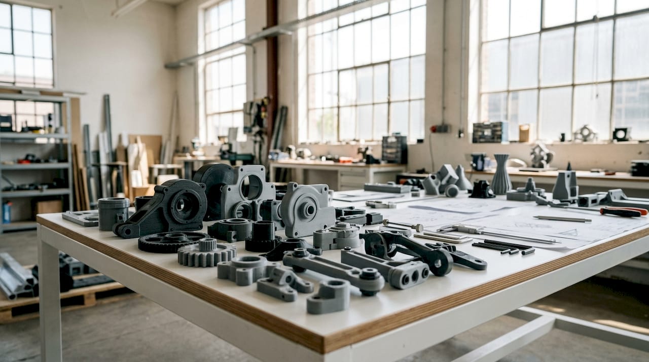
Traditional manufacturing forces engineers to split complex shapes into multiple pieces because molds and mills have geometric limits. 3D printing has no such constraint. A bracket, housing, and clip that once required three separate parts, three purchase orders, and an assembly step can print as one.
The practical benefits of consolidation follow a clear sequence:
- Fewer part numbers. Each eliminated component removes a purchase order, a supplier relationship, and a quality inspection point.
- No fastener costs. Screws, inserts, and adhesives add unit cost and assembly time. Consolidated parts need none.
- Reduced assembly risk. Every joint is a potential failure point. Fewer joints mean fewer failure modes.
- Simpler supply chains. Consolidating multiple parts into a single print reduces supply chain complexity and improves functional performance.
- Lower labor costs. Assembly time drops directly when there is nothing to assemble.
One important boundary: consolidation works best for static parts. Moving components, parts that need replacement, or assemblies requiring different materials should remain separate. Printing a hinge as one piece sounds appealing until the hinge wears out and the entire housing must be replaced.
3. Improving mechanical performance through design choices
3D printing is anisotropic. Interlayer bond strength is 50–70% of in-layer strength, which means a part’s orientation during printing directly determines where it will fail under load. This is the most underestimated mechanical variable in additive manufacturing.
The fix is straightforward: orient critical load paths parallel to the XY plane. A bracket that carries tensile load along its length should be printed so that load runs across layers, not between them. Engineers who treat print orientation as an afterthought consistently produce weaker parts than the material’s datasheet suggests.
Key design choices that improve mechanical performance:
- Fillets on internal corners. Fillets increase part strength by up to 200% by spreading stress across a curved surface instead of concentrating it at a sharp corner. This is one of the highest-return changes available at zero material cost.
- Internal lattice structures. Gyroid and octet truss lattices at 20–30% density deliver 80% of solid infill strength with significantly less material and print time. They outperform simple grid infill for most structural applications.
- Wall thickness matched to load. Thin walls flex and fail. Walls at 3–4 perimeters handle most functional loads without adding unnecessary mass.
- Avoid sharp internal transitions. Sudden changes in cross-section create stress risers. Gradual tapers distribute load more evenly.
Pro Tip: Do not default to 100% infill for structural parts. A gyroid pattern at 25% infill with four perimeter walls often outperforms solid infill in impact resistance while cutting print time by a third.
The 3D part optimization process for engineers goes deeper on matching infill patterns to specific load cases, which is worth reviewing before finalizing any functional part design.
4. Faster prototyping and fewer costly redesigns
The “Rule of 10” states that fixing a design issue becomes ten times more costly at each later stage of development. A change that costs $1 to fix in CAD costs $10 in prototyping, $100 in pre-production, and $1,000 after launch. DfAM shifts those fixes to the cheapest possible moment.
Engineers who integrate DfAM analysis before the first print catch geometry problems, wall thickness violations, and orientation issues in software rather than on the build plate. The result is fewer failed prints, fewer engineering change orders, and faster time to market.
Specific practices that accelerate prototyping cycles:
- Run a printability check before slicing. Tools that flag unsupported overhangs, thin walls, and non-manifold geometry catch errors in minutes that would otherwise waste hours of print time.
- Design for faster iteration cycles. Break complex parts into modular sections during early development. Print and test the critical feature first, not the entire assembly.
- Validate wall thickness against your printer’s minimum. Most FDM printers require walls at least 1.2mm thick for structural integrity. Thinner walls print inconsistently and fail early in testing.
- Use simulation before physical prints. FEA tools applied to the DfAM model identify weak points before any filament is consumed.
Early DFM involvement reduces overall project cost significantly by addressing manufacturing constraints before redesigns become necessary. The engineers who treat DfAM as a checklist item at the end of design consistently spend more time and money than those who run it in parallel with concept development.
Key Takeaways
DFM in 3D printing delivers the greatest returns when applied at the concept stage, not after the first failed print.
| Point | Details |
|---|---|
| Self-supporting geometry cuts costs | Angles above 45° eliminate supports, reducing print time by 20–40% and post-processing labor. |
| Part consolidation changes economics | DfAM enables up to 90% part consolidation, cutting BOM complexity by 50–80% and eliminating assembly steps. |
| Orientation determines strength | Load paths parallel to the XY plane avoid the 50–70% interlayer strength penalty in FDM parts. |
| Fillets are free strength | Internal corner fillets increase part strength by up to 200% with no added material cost. |
| Fix issues early or pay more | The Rule of 10 means a design fix in CAD costs a fraction of the same fix after production starts. |
Why most engineers get DfAM backwards
The most common mistake I see product developers make is treating DfAM as a finishing step. They complete the CAD model, send it to the printer, watch it fail, and then ask what went wrong with the print. The print did not go wrong. The design did.
The real value of DfAM is not in correcting prints. It is in making the design think like a printer from the first sketch. That shift requires cross-functional conversation between the engineer who owns the geometry and the person who understands the machine. When those two people work in parallel rather than in sequence, the number of failed builds drops sharply.
I have also seen teams resist part consolidation because it feels like a risk. Combining three parts into one means redesigning all three if something goes wrong. That logic sounds reasonable until you calculate the assembly labor, fastener costs, and supply chain overhead you are carrying every single production run. The consolidated part almost always wins on total cost.
The insight worth internalizing is this: viewing DfAM as simply printing traditional CNC designs misses its core value. Additive manufacturing unlocks geometries that subtractive methods cannot produce at any price. Engineers who design for those capabilities, rather than around them, build better products faster.
— Justin
Cc3dlabs brings DfAM expertise to your production workflow
Product developers who want DfAM applied from the first file, not retrofitted after a failed build, get better results with a manufacturing partner who understands both design and process.

Cc3dlabs offers professional 3D printing services built around manufacturing-grade quality, including design support, multi-color filament printing, and CAD modeling for clients near Philadelphia and shipping nationally. The team works with product developers and engineers on prototypes, functional parts, and batch production runs where DfAM principles are applied from the start. Getting a free online estimate takes minutes, and the design review process catches printability issues before they cost you a build. If you are ready to cut 3D printing costs through smarter design, Cc3dlabs is the right starting point.
FAQ
What are the main benefits of DFM in 3D printing?
DFM in 3D printing reduces print times by 20–40%, lowers material costs by eliminating support structures, improves part strength through better geometry, and cuts redesign costs by catching issues before production starts.
How does DfAM differ from traditional DFM?
Traditional DFM focuses on subtractive constraints like tool access and draft angles. DfAM focuses on additive constraints like overhang angles, layer orientation, and part consolidation opportunities that subtractive methods cannot achieve.
What is the 45° rule in 3D printing?
Surfaces angled greater than 45° from horizontal are self-supporting in FDM printing and require no support structures, which reduces print time, material use, and post-processing labor.
How much can part consolidation reduce assembly costs?
DfAM enables up to 90% part consolidation, which eliminates fasteners, reduces assembly time by 20 minutes or more per unit, and cuts BOM complexity by 50–80%.
When should DFM analysis happen in the design process?
DFM analysis should run in parallel with concept development. The Rule of 10 means fixing a design issue in CAD costs a fraction of fixing the same issue after production begins.