
TL;DR:
- Engineers often overlook that proper part orientation, wall count, and design choices significantly improve strength and reduce support needs. Focusing on defining requirements before slicing ensures optimal geometry, load paths, and fit, minimizing material waste and print time. Validating mating interfaces with small test prints early can prevent costly reprints and streamline production.
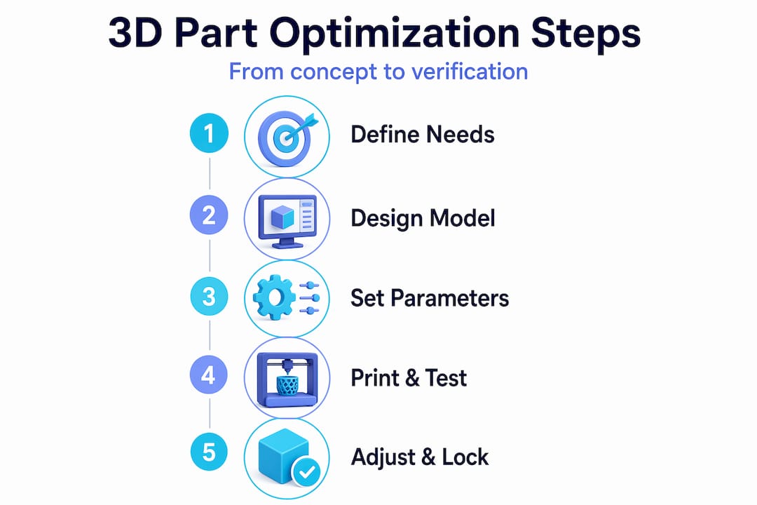
Every engineer who has pulled a brittle, support-crusted print off the bed and thought “this should have worked” knows the real cost of skipping the 3d part optimization process. Poor orientation choices, default infill settings, and designs that weren’t built with additive manufacturing in mind waste filament, machine time, and development cycles. The good news: optimization isn’t guesswork. It’s a structured sequence of decisions that starts before you touch your slicer and ends only after you’ve validated the finished part. This guide walks you through that sequence, step by step.
Table of Contents
- Key takeaways
- The 3D part optimization process starts with requirements
- Execution phase 1: print settings that actually build strength
- Execution phase 2: cutting supports and controlling fit
- Verification phase: test, adjust, and lock in
- What I’ve learned after watching engineers skip these steps
- Get expert support for your optimization workflow
- FAQ
Key takeaways
| Point | Details |
|---|---|
| Start with requirements, not settings | Define load paths, fit requirements, and production volume before opening your slicer. |
| Orientation beats infill for strength | Aligning loads parallel to layer lines delivers more strength per gram than chasing high infill percentages. |
| Walls drive structural performance | Increasing perimeter count from 2-3 to 4-6 can dramatically improve tensile strength with minimal added print time. |
| Design out supports early | Chamfers, 45° self-supporting angles, and split-part strategies reduce material waste before printing begins. |
| Validate interfaces before full runs | Printing only critical mating sections first catches fit issues early and protects your full material budget. |
The 3D part optimization process starts with requirements
Before you adjust a single slicer setting, you need to know exactly what the part has to do. That sounds obvious, but a surprising number of optimization failures trace back to this step being skipped or treated superficially.
Ask four questions about every part you intend to print:
- What loads will it carry? Tensile, compressive, torsional, impact? Each favors different orientation and material choices.
- Does it mate with anything? Threads, press fits, snap fits, and sliding interfaces all require tight tolerance control that must be planned, not fixed in post-processing.
- What’s the surface finish requirement? A cosmetic panel and a functional bracket can share the same material but need completely different layer heights and orientation decisions.
- How many are you producing? A single prototype tolerates extra support and slower speeds. A batch of 200 functional parts does not.
Understanding these requirements directly shapes your decisions about part orientation, wall strategy, and infill density in every phase that follows. This integrated thinking across design and settings is what separates a deliberate optimization process from random trial and error.
Design for additive manufacturing principles apply here too. The most effective way to reduce supports is to design a part that doesn’t need them. Self-supporting geometry relies on keeping overhangs at or below 45° from vertical. Steeper angles require support material, which adds print time, wastes filament, and often leaves surface artifacts where the support contacted the part. When a feature requires a steep overhang, replacing it with a chamfer or splitting the part into two printable sections is almost always the better call. If you’re still developing your design workflow for manufacturing, locking in these principles at the modeling stage pays dividends across every print you run.
Pro Tip: When designing for batch production, model your split lines and chamfers as first-class design decisions, not afterthoughts. A five-minute geometry change during CAD can eliminate 40 minutes of support removal per unit.
Execution phase 1: print settings that actually build strength
Once your design respects the geometry rules, your slicer decisions determine whether the part meets its mechanical targets. The priority order here matters more than most engineers expect.
-
Set orientation first. Parts are strongest along the X-Y plane because FDM materials exhibit layer anisotropy. Loads applied parallel to the layer plane are resisted by the full cross-section of the material. Loads applied perpendicular to layers rely on interlayer adhesion, which is the weakest bond in any FDM part. Orient the part so your primary load path runs parallel to the print bed whenever geometry allows.
-
Choose nozzle size based on the part’s demands. A 0.4mm nozzle is a reasonable default, but it isn’t always right. Coarse structural parts with no fine features print faster and often stronger through a 0.6mm or 0.8mm nozzle because thicker extrusions bond better. Fine detail parts may need a 0.2mm nozzle. Choosing the wrong nozzle size means you’re either wasting time or sacrificing resolution you didn’t need to sacrifice.
-
Prioritize walls over infill. This is where most engineers leave performance on the table. The priority decision-stack treats infill as supplemental, not structural. Infill supports the shell and transfers minor loads between walls. The walls themselves are load-bearing. Increasing perimeters from 2-3 to 4-6 can roughly double tensile strength with a fraction of the material cost that the same result would take with infill alone.
-
Set layer height based on finish and throughput needs. Thinner layers improve surface quality and bonding at a cost of print time. Thicker layers print faster with slightly reduced Z-direction resolution. For structural parts where finish matters less, 0.2mm to 0.3mm is a solid range. For cosmetic or precision-fit surfaces, 0.1mm to 0.15mm is worth the added time.
-
Dial in extrusion width and print speed together. Slightly over-extruding, setting extrusion width to 110-120% of nozzle diameter, improves layer bonding significantly. Pair that with conservative print speeds on outer walls and you get noticeably better surface finish without changing any material or hardware.
Pro Tip: Print your structural outer walls at 50-60% of your standard print speed. The inner walls and infill can run fast. The outer wall bond quality is what you’ll feel when you load the part.
If you want a consolidated view of how to reduce print costs without sacrificing mechanical performance, the relationship between wall count and infill is a good place to start.
Execution phase 2: cutting supports and controlling fit
Support material is the single most expensive line item in many print budgets. You pay for it in filament, print time, and post-processing labor. The goal of the 3d printing optimization process at this stage is to minimize supports through geometry choices, not just slicer settings.
Key tactics to reduce support usage:
- Replace any overhang steeper than 45° with a chamfer or stepped feature. Avoiding steep overhangs by design eliminates support needs at the source, which is far more material-efficient than generating supports and then removing them.
- Split complex parts along natural support-free planes and bond or fasten them after printing. Two clean parts printed without support often outperform one supported print both mechanically and dimensionally.
- Use slicer-level support controls as a last resort. Adjusting support overhang thresholds, interface layers, and Z-distance can reduce support volume and ease removal, but these are refinements to a design problem, not solutions.
Dimensional accuracy requires its own set of deliberate choices. Press fits and snap fits are particularly unforgiving. The standard approach of modeling a hole at nominal diameter and hoping the printer hits it rarely works without calibration. You need to run a calibration print for your specific material and temperature combination and capture your actual shrinkage coefficient before committing to tolerance-critical dimensions.
Pro Tip: For any part with a mating interface, print just the mating zone as a standalone test piece before running the full part. This fit-check approach uses under 3g of filament and roughly 30 minutes of print time to verify whether your tolerance assumptions are correct. It will save you full reprints.
Verification phase: test, adjust, and lock in
The 3d part optimization process does not end when the print finishes. A part that looks correct can still fail under load, exhibit unexpected surface artifacts, or refuse to mate with its counterpart. Verification is where you close that gap between what you designed and what the printer produced.
Follow this sequence for each new part or revised iteration:
- Print mating-section test pieces first. Fit-check prints isolate interface risk before you commit filament to the complete part.
- Evaluate the test piece dimensionally and functionally. Measure the actual feature dimensions against nominal. Check clearance, press force, snap engagement, or whatever the fit requirement specifies.
- Adjust tolerances in the model or slicer based on measured deviations. A 0.1mm to 0.2mm compensation is common for most FDM setups.
- Print the full part and evaluate strength and surface finish against your original functional requirements.
- Apply post-processing where the part still falls short. Annealing improves crystalline polymer strength. Epoxy coating improves surface hardness and moisture resistance. Sanding or chemical smoothing addresses cosmetic finish.
The table below summarizes what to adjust based on common verification failures:
| Failure Mode | Likely Cause | Adjustment |
|---|---|---|
| Part fractures under load | Weak layer adhesion or poor orientation | Reorient load path, increase wall count, reduce print speed |
| Mating interface too tight | Insufficient tolerance compensation | Add 0.1-0.2mm clearance to hole features |
| Mating interface too loose | Over-compensated tolerances | Reduce clearance offset, recheck calibration |
| Poor surface finish on top layers | Inadequate top layer count | Increase top solid layers to 5-6 |
| Warping or delamination | Cooling or adhesion issues | Reduce cooling fan speed, increase bed temperature |
For low-volume production, this iteration cycle often runs two to three times before settings are locked. For scaled manufacturing runs, the investment in that early iteration cycle pays back in reduced scrap rates across every subsequent print.
What I’ve learned after watching engineers skip these steps
In my experience working on functional print projects, the single most consistent mistake I see product developers make is treating infill as the primary strength lever. They see a weak part and immediately bump infill from 20% to 60%. That consumes significantly more material and adds print time, but delivers far less strength improvement than simply adding two perimeter walls would have.
I’ve watched teams spend days reprinting support-heavy assemblies because the support geometry was never questioned at the design stage. A split-part strategy, something that would have taken an hour to model, would have eliminated the entire problem. The labor cost of support removal is rarely factored into part cost calculations, but it should be.
What I’ve found actually works is this: treat the first iteration of any new part as a learning print, not a production print. Print the mating sections, validate them, check your orientation against the load path, and then run the full part. That discipline, applied consistently, shortens development cycles more than any single settings trick. And early design validation before committing to full runs is the clearest signal I know that an engineering team is thinking about optimization the right way.
— Justin
Get expert support for your optimization workflow

If you’re working through a print optimization challenge and want experienced support behind your production process, Cc3dlabs is built for exactly that. Located near Philadelphia, Cc3dlabs provides precision printing and design support for product developers and engineers running prototypes, functional parts, and batch production orders. Their team handles orientation strategy, tolerance validation, and material selection as part of every project, so your parts arrive ready to function, not just ready to look at. From on-demand part production to professional handheld 3D scanning (accuracy to ~0.1 mm) for fit verification, Cc3dlabs offers the technical depth that turns optimization principles into consistent, repeatable results.
FAQ
What is the first step in the 3D part optimization process?
Define your functional requirements before touching your slicer. Understanding load paths, fit requirements, surface finish needs, and production volume shapes every orientation and settings decision that follows.
Does infill percentage affect part strength more than wall count?
No. Wall count dominates strength per unit of material in FDM parts. Increasing perimeters from 2-3 to 4-6 delivers significantly more tensile strength than equivalent infill increases, with less added filament.
How do I reduce support material when optimizing printed parts?
Design out supports by keeping overhangs at or below 45° and using chamfers or split-part strategies in your CAD model. Support avoidance by design is consistently more material-efficient than generating and removing supports after printing.
How should I validate fit before committing to a full print run?
Use your slicer to isolate and print only the mating-interface section of the part first. These fit-check test pieces use minimal filament and print quickly, letting you verify tolerance accuracy before running the complete part.
Why does part orientation matter so much in 3D printing optimization?
FDM parts are anisotropic. Strength along the X-Y plane is significantly higher than across layer boundaries. Orienting the part so primary loads run parallel to layers is one of the highest-return decisions in the entire optimization process.