
TL;DR:
- Achieving precise 3D prints relies on proper hardware calibration, environment control, and process documentation.
- Follow a systematic calibration sequence: E-steps, flow rate, temperature, XY compensation, then verify with a calibration cube.
- Consistent accuracy requires rigorous QC, documentation, and functional testing rather than solely relying on test models.
A single millimeter of dimensional error can turn a promising prototype into a costly restart. For product developers and small manufacturers, a bracket that doesn’t seat properly, a housing that won’t close, or a functional part that binds under load isn’t just frustrating — it’s a schedule killer. The good news is that most accuracy failures in FDM 3D printing trace back to a handful of fixable root causes: uncalibrated hardware, poorly chosen parameters, and skipped verification steps. Work through those systematically, and you can hit repeatable tolerances that actually serve your design intent.
Table of Contents
- What you need for precise 3D printing
- Step-by-step calibration for dimensional accuracy
- Print parameter tuning for accuracy and performance
- Verifying accuracy and troubleshooting common issues
- Getting repeatable results: Best practices for production and QC
- Our take: Why print accuracy isn’t just about numbers
- Accurate 3D printing starts with the right partner
- Frequently asked questions
Key Takeaways
| Point | Details |
|---|---|
| Preparation is key | Gather the right tools, environment, and expectations to set the stage for print accuracy. |
| Follow calibration order | Calibrate extruder steps, flow rate, and temperature in sequence for the most consistent results. |
| Tweak parameters wisely | Adjust speed, temperature, and layer height according to your printer and project needs. |
| Verify and troubleshoot | Always measure finished prints and address issues like shrinkage, over-extrusion, and first layer errors. |
| Quality control drives consistency | Document processes and apply standards for repeatability and reliability in production. |
What you need for precise 3D printing
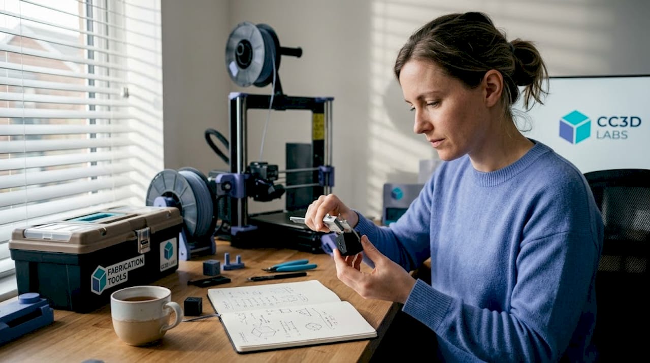
Before diving into specific steps, understand what gear and setup you need for successful, accurate prints. Skipping this foundation is one of the most common reasons teams struggle with dimensional consistency even after hours of calibration work.
Essential hardware and tools:
- A printer with a rigid frame and quality linear motion components (linear rails improve consistency significantly)
- Digital calipers accurate to 0.01mm for measuring test prints
- A feeler gauge set for bed leveling
- A known-weight filament spool from a reputable supplier
- Calibration test models (single-wall cubes, calibration towers, XY compensation squares)
Software requirements:
- A capable slicer such as PrusaSlicer, Cura, or OrcaSlicer with calibration tools built in
- Firmware that supports input shaping and pressure advance (Klipper or Marlin 2.x)
- A spreadsheet or calibration log to track every change you make
Your environment matters more than most people expect. Temperature swings in your print space directly affect filament viscosity and cooling behavior, both of which shift your dimensions. Aim for a room temperature between 65°F and 75°F with minimal airflow drafts around the printer. Enclosures help with materials like ABS and Nylon that are sensitive to ambient temperature.
Set realistic expectations based on your hardware. Industry benchmarks show tuned mid-range FDM printers achieve ±0.1–0.2mm, linear rail systems reach ±0.05–0.15mm, and Stratasys industrial FDM systems hold dimensional variation within 2%. Understanding print accuracy basics before you start calibrating helps you avoid chasing tolerances your hardware simply can’t deliver.
| Printer type | Typical achievable tolerance | Best use case |
|---|---|---|
| Budget FDM (Cartesian) | ±0.2–0.4mm | Concept models, non-critical parts |
| Tuned mid-range FDM | ±0.1–0.2mm | Functional prototypes, fixtures |
| Linear rail FDM | ±0.05–0.15mm | Precision parts, snap fits |
| Industrial FDM (Stratasys) | ±0.05–0.1mm | Production-grade components |
For manufacturing-grade 3D printing that needs to meet engineering specs, investing in a quality machine and a controlled environment isn’t optional — it’s the baseline.
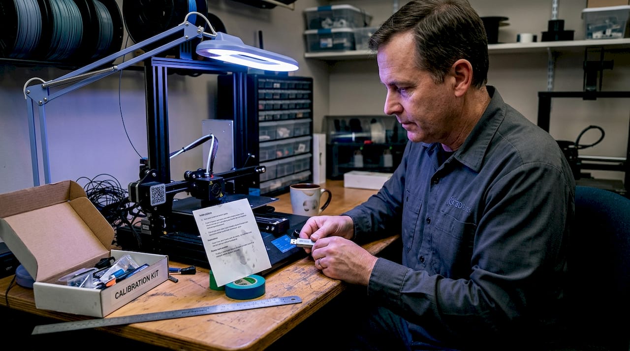
Pro Tip: Keep a dedicated calibration kit in a labeled box next to your printer: a set of calipers, a test print USB or SD card, and a printed log sheet. Calibration done without documentation is just guessing.
Step-by-step calibration for dimensional accuracy
Once you have what you need, follow these concrete steps to calibrate your printer for true dimensional accuracy. The order matters. Skipping ahead or doing steps out of sequence creates compounding errors that are very hard to trace.
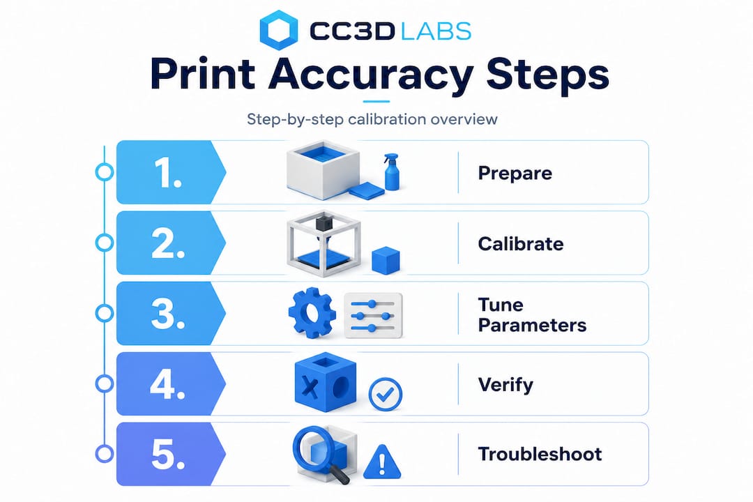
The correct calibration sequence is: calibrate extruder E-steps first, then flow rate using a single-wall test, followed by temperature tuning, XY compensation, and finally verify everything with a calibration cube.
Calibration sequence:
-
Calibrate E-steps. Measure 100mm of filament from the extruder entrance, command the extruder to feed 100mm, and measure what actually moved. Adjust E-steps with the formula: New E-steps = (Current E-steps × 100) ÷ Actual mm fed. This is your foundation. Every other calibration assumes your extruder is delivering accurate filament length.
-
Tune flow rate with a single-wall test. Print a single-wall box (no infill, no top/bottom layers) and measure wall thickness with calipers. Your measured wall should equal your nozzle diameter. If it reads 0.48mm on a 0.4mm nozzle, reduce flow rate by approximately 17%. The formula: New flow = (Nozzle diameter ÷ Measured wall) × Current flow %. This step catches over-extrusion that inflates all your external dimensions.
-
Run a temperature tower. Print a temperature tower model and inspect each section for stringing, layer adhesion, and surface quality. Pick the temperature zone that gives the cleanest surface with no stringing. For PLA this is typically 195°C to 215°C, but it varies by brand and color.
-
Apply XY compensation. Print a calibration square and measure the actual outer dimensions versus the model dimensions. Most slicers let you apply an XY contour compensation value (typically 0.1mm to 0.2mm inward for holes, outward for outer profiles) to correct for systematic over-extrusion on perimeters.
-
Verify with a calibration cube. Print a 20mm calibration cube and measure all three axes. Your target is within ±0.2mm on a tuned mid-range printer. If Z is off, check your layer height settings and leadscrew pitch.
| Calibration step | Accuracy impact | Difficulty | Time required |
|---|---|---|---|
| E-steps | Very high | Low | 10 minutes |
| Flow rate | High | Low | 20 minutes |
| Temperature tuning | Medium | Medium | 45 minutes |
| XY compensation | High | Low | 15 minutes |
| Calibration cube verify | Diagnostic | Low | 30 minutes |
For parts that will be measured against designing reliable prototypes standards, a high quality scan calibration process can validate your physical output against the original CAD geometry, catching errors that calipers alone might miss.
Pro Tip: Always recalibrate after any maintenance: nozzle swap, belt tension adjustment, or firmware update. What was accurate last week may not be accurate today.
Print parameter tuning for accuracy and performance
After basic calibration, dial in print parameters for your specific machine and project needs. Calibration sets your baseline, but parameter tuning is where you optimize for the part in front of you.
Research on PLA FDM printing shows that printer-specific optima vary significantly. The Prusa MK4 performs best at lower speeds (20–40mm/s) with a higher nozzle temperature (around 230°C) and small layer heights (0.05mm for fine detail). The LulzBot TAZ Pro handles higher speeds (40–60mm/s) and thicker layers (0.2mm) more effectively. Lower layer heights generally improve XY accuracy by reducing the staircase effect on curved surfaces.
| Parameter | Prototype run | Functional/production part |
|---|---|---|
| Print speed | 40–60mm/s | 20–40mm/s |
| Layer height | 0.15–0.2mm | 0.05–0.1mm |
| Nozzle temperature | Manufacturer default | Fine-tuned per material batch |
| Cooling fan | 100% | 50–80% (material dependent) |
| Perimeter count | 2–3 | 3–5 |
Quick tuning tips for production versus prototype runs:
- For concept prototypes, prioritize speed over fine detail. Use 0.2mm layers and 50mm/s to get a physical model in hand quickly.
- For functional parts with tight fits, drop to 0.1mm layers and 30mm/s on perimeters. Slow perimeters reduce ringing artifacts that distort edge dimensions.
- For batch production, lock in a parameter profile and save it as a named preset. Never tweak a production profile mid-run.
- Use pressure advance (or linear advance in Marlin) to reduce corner bulging, which is one of the most common causes of oversized outer dimensions.
- Check out this manufacturing optimization checklist for broader process efficiency ideas that complement your print parameter strategy.
For low-volume print tips that balance speed with accuracy, the key is treating each small batch like a mini production run: same parameters, same filament brand, same environment. And if you’re working with specialty materials, our guide to precision with filament printing covers material-specific parameter strategies in detail.
Pro Tip: Document every parameter change per project in a simple spreadsheet. Note the date, filament batch number, temperature, speed, and measured output. Six months from now, when a client reorders, you’ll reproduce the result in one print instead of three.
Verifying accuracy and troubleshooting common issues
Once your parts are printed, verifying their accuracy and resolving any issues should be routine, not an afterthought.
Measuring and verifying part dimensions:
- Let parts cool fully before measuring. Warm PLA is slightly flexible and will read smaller than it actually is once rigid.
- Use digital calipers for features above 1mm. For bore diameters and precision holes, use a calibrated pin gauge set.
- Measure at multiple points on the same feature. A hole that reads 5.00mm at the top may read 4.85mm at the bottom if elephant’s foot is present.
- Compare all critical dimensions to your CAD drawing, not just the nominal size. Note deviations by axis and by feature type.
- Use PrusaSlicer’s built-in dimensional accuracy test, which includes an XYZ cross gauge with holes to check shrinkage and XY skew simultaneously.
Troubleshooting common accuracy problems:
- Elephant’s foot: First layer squishes outward by roughly 0.2mm per side. Fix it by increasing the initial layer height slightly or using your slicer’s elephant’s foot compensation setting.
- Over-extrusion on outer walls: Mimics an E-steps error but is actually a flow rate problem. Calibrate flow first before touching steps/mm.
- Oversized holes: Apply XY compensation of 0.1 to 0.2mm inward for holes in your slicer. This is separate from your outer profile compensation.
- XY skew: If your calibration square prints as a parallelogram, use your slicer’s skew correction tool to dial in the actual angle of your motion system.
Material shrinkage matters. PLA shrinks 0.3–0.5% as it cools. For a 100mm part, that’s up to 0.5mm of dimensional loss. Scale your model up by the shrinkage percentage, or use your slicer’s shrinkage compensation field. ABS and Nylon shrink significantly more and require enclosures plus active compensation to hit tight tolerances.
Slicer tools are underused by most teams. PrusaSlicer’s built-in tools include XY skew correction, flow calibration tests, and a dimensional accuracy test model that gives you a complete picture of your printer’s current state in a single print. Run this test after every major calibration session and keep the results in your log.
For parts where accuracy is truly non-negotiable, review the critical print accuracy factors that go beyond slicer settings and into design and material choices.
Getting repeatable results: Best practices for production and QC
Beyond a single print, consistent accuracy demands reliable quality control. One good print doesn’t mean your process is stable. Repeatability is what separates a calibrated machine from a production-ready process.
Core best practices for process consistency:
- Write a one-page print process document for each recurring part: material, brand, profile name, bed surface, and post-processing steps.
- Tag every batch with the filament lot number. Material properties vary between lots, and tracking this is the fastest way to diagnose unexpected dimensional shifts.
- Perform a first-article inspection on the first part of every new batch. Measure all critical dimensions before committing the full run.
- Assign specific operators to specific machines where possible. Operator-to-machine consistency reduces variability significantly.
- Schedule preventive maintenance on a fixed interval: belt tension, nozzle condition, and bed surface replacement. Don’t wait for failures.
ISO 5725 standards define accuracy as bias (how close to true value) and precision as repeatability and reproducibility across operators and time. Applying this framework to your 3D printing process means you’re not just checking one print — you’re validating that your process delivers consistent results across shifts, machines, and team members.
Post-processing is often the final step to hitting the tightest tolerances. Reaming critical bores to a final diameter, light sanding of mating surfaces, or a quick pass with a file on snap-fit features can take a ±0.2mm printed part to a ±0.05mm functional fit. Plan for this in your design and your schedule.
For teams that need precise estimates for QC planning and budgeting, knowing your expected scrap rate and post-processing time per part is essential for accurate project costing.
Our take: Why print accuracy isn’t just about numbers
Here’s something we’ve seen repeatedly: teams spend hours chasing a perfect calibration cube score, then send a functional bracket to assembly and discover it doesn’t fit the mating part. The cube was perfect. The bracket was wrong. Why? Because dimensional accuracy in isolation doesn’t account for how a part actually functions in context.
The real test of print accuracy is assembly fit and end-use performance, not caliper readings on a test model. A hole that measures 5.02mm on a calibration print may still bind on a 5.0mm shaft because of surface texture, material compliance, or thermal expansion in service. Conversely, a part that reads 0.15mm undersized might assemble perfectly because the mating part has a complementary tolerance.
This is where an application-first mindset pays off. Before you set a dimensional target, ask: what does this part actually need to do? A snap-fit clip needs a specific deflection range, not a specific wall thickness. A bearing housing needs a specific press-fit interference, not a perfect 20mm cube score. Design your verification around the functional requirement, not the geometric ideal.
Teams also tend to measure what’s easy (outer dimensions, wall thickness) and skip what’s hard (hole roundness, flatness, perpendicularity). Those harder-to-measure features are often exactly where assembly problems hide.
Our advice: always review printed parts as part of the design and assembly process. Fit them to their mating components. Test the function. Use calipers as a diagnostic tool, not as the final verdict. And when you’re designing parts for tight tolerances, reliable prototypes by design gives you the framework to build accuracy into your geometry from the start.
Accurate 3D printing starts with the right partner
Precision matters at every stage of product development, from the first prototype to a production batch. If your team is spending more time troubleshooting dimensional errors than iterating on design, the problem might not be your calibration skills — it might be the equipment and process behind your prints.

At CC 3D Labs, we bring calibrated, production-ready 3D printing services to product developers and manufacturers who need parts that are right the first time. Whether you’re producing prototypes and functional parts for fit-and-function testing or running a batch of production components, our quality-controlled process handles the calibration, parameter tuning, and first-article verification so you don’t have to. Get started with on-demand 3D printing and request a free online estimate today.
Frequently asked questions
What is a typical tolerance for high-accuracy FDM 3D printing?
Well-calibrated FDM printers can achieve tolerances of about ±0.1 to ±0.2mm, with advanced linear rail systems reaching as tight as ±0.05mm on a well-maintained machine.
How do I fix oversized holes in my 3D prints?
Apply XY hole compensation of 0.1 to 0.2mm inward in your slicer settings, and always calibrate your flow rate before adjusting steps/mm to avoid compounding errors.
Do layer height and print speed affect dimensional accuracy?
Yes; lower layer heights improve XY accuracy by reducing staircase effects on curved surfaces, while slower perimeter speeds reduce corner bulging that inflates outer dimensions.
Why do my prints measure smaller after cooling?
PLA shrinks 0.3–0.5% as it cools from print temperature to room temperature, so scaling your model up slightly or using your slicer’s shrinkage compensation field corrects for this predictable loss.
How can I verify my 3D printer’s repeatability?
Print calibration parts in batches across multiple sessions, measure all critical dimensions, and evaluate results using ISO 5725 bias and precision criteria to confirm consistency across operators and time.
Recommended
- Why Print Accuracy Is Critical for 3D Prototyping
- How to scan objects for 3D printing: accurate steps
- Step-by-Step 3D Printing: Guide to Quality Prototypes
- How to design 3D prints: reliable prototypes & parts
- Step by Step Shaft Design for Precision Applications
- How to design optical glass: expert steps for precision results – Precision Glass