Technician prepares part in 3D scanning lab

How we achieve a high quality 3D scan for manufacturing

Achieving precision in 3D scanning can transform your manufacturing workflow, but many product developers struggle with incomplete data, reflective surface challenges, and uncertainty about scan accuracy. This comprehensive guide walks you through every step of the high quality 3D scan process, from surface preparation and equipment setup to execution, troubleshooting, and verification. You’ll learn proven techniques to capture complete geometry, handle difficult materials, and validate scan quality using quantitative metrics. Whether you’re creating prototypes or functional parts, mastering these methods ensures your scans deliver the accuracy your projects demand.

Table of Contents

Key Takeaways

Point Details
Preparation boosts accuracy Thorough preparation reduces missing geometry and data noise before you scan.
Surface handling strategies Apply scanning spray to reduce reflectivity and use adhesive markers to aid alignment across passes.
Plan multi angle scans Plan scan passes from multiple angles to capture geometry with sufficient overlap for full data.
Post scan verification Evaluate scan quality with quantitative metrics to confirm completeness and reliability after data capture.

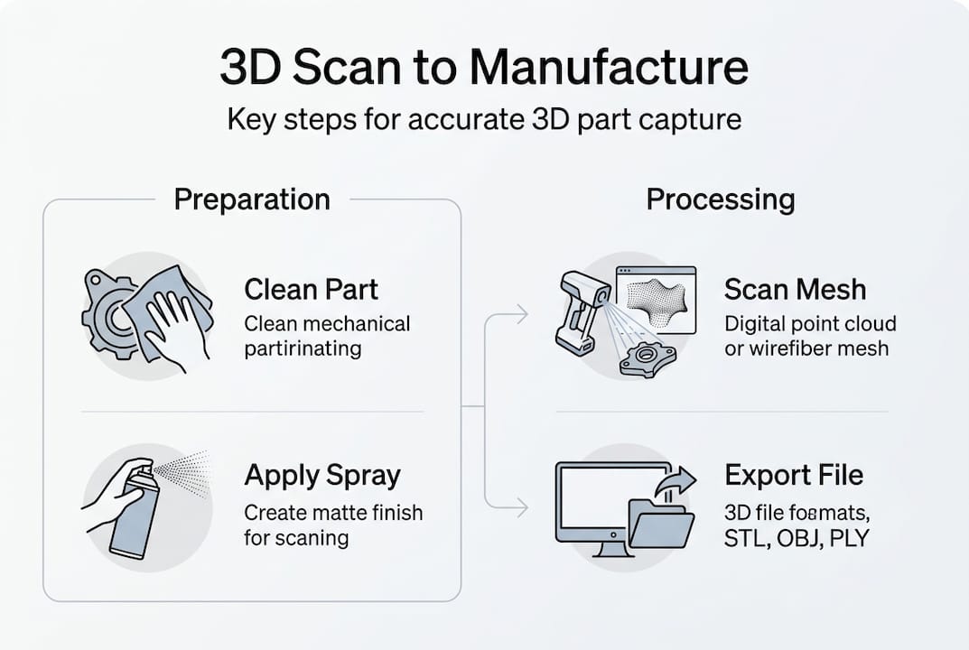
Preparing for a high quality 3D scan

Successful 3D scanning starts long before you power up the equipment. Your preparation phase determines whether you’ll capture clean, complete data or spend hours troubleshooting missing geometry and noise artifacts. Product developers who skip this stage often face repeated scans and project delays.

Start by examining your part’s material properties and surface characteristics. Reflective and black surfaces cause data loss that derails even expensive scanning equipment. Shiny metal components, glossy plastics, and dark rubber parts scatter or absorb the scanner’s light, creating gaps in your point cloud data. Document these problem areas before you begin.

Apply scanning spray to reduce reflectivity on challenging surfaces. This temporary coating creates a matte finish that allows scanners to capture accurate geometry. Choose sprays that evaporate cleanly without residue, especially for parts heading to production. For transparent or highly reflective areas, consider using adhesive markers to give the scanner tracking points. These reference dots help the software align multiple scan passes and maintain accuracy across complex geometries.

Your scanning environment matters as much as surface preparation. Control ambient lighting to prevent interference with the scanner’s projected patterns. Natural sunlight and fluorescent fixtures can introduce noise that corrupts your data. Set up in a space with consistent, diffuse lighting or use blackout conditions for optimal results. Secure your part on a stable platform that won’t shift during scanning. Even minor vibrations translate to measurement errors.

Create an equipment checklist before each session:

  • Calibrated scanner with fresh calibration verification
  • Scanning spray and application tools
  • Reference markers and adhesive
  • Stable mounting platform or turntable
  • Controlled lighting setup
  • Clean lens and projection surfaces

Pro Tip: Test your setup on a simple geometric shape before scanning complex parts. A calibration cube or cylinder helps you verify that your preparation steps are working and your scanner is performing within specification.

Our 3D scanning lab handles these preparation challenges daily, ensuring every scan starts with optimized conditions for maximum accuracy.

Executing the 3D scan: step by step instructions

With preparation complete, you’re ready to capture high quality scan data. The execution phase requires methodical technique and attention to scanner settings. Rushing through this process guarantees you’ll need to rescan, wasting time and potentially damaging spray coated surfaces.

  1. Select your scanner type based on accuracy requirements and working environment. Portable scanners trade some accuracy for shop floor usability, while stationary systems deliver laboratory grade precision. Match the tool to your tolerance specifications and workspace constraints.
  2. Calibrate the scanner immediately before use. Temperature changes and transport can affect measurement accuracy. Run the manufacturer’s calibration routine and verify results against a known reference object. Document calibration data for quality records.
  3. Plan your scanning path to capture geometry from multiple angles. Complex parts require overlapping scan passes to ensure complete coverage. Start with broad passes to capture overall shape, then focus on detailed features like holes, edges, and fine textures. Rotate the part systematically rather than moving the scanner erratically.
  4. Adjust exposure settings for reflective surfaces. If scanning spray didn’t completely eliminate shine, reduce scanner sensitivity to prevent oversaturation. Modern scanners offer exposure bracketing that captures multiple passes at different settings, giving you clean data even on challenging materials.
  5. Switch to infrared or blue light modes when scanning metallic or highly reflective parts. Different wavelengths interact with surfaces in unique ways. Blue light often penetrates thin translucent materials better, while infrared reduces glare on polished metals. Experiment with these settings during your test scans.
  6. Monitor data quality in real time through the scanner software. Most systems display point cloud density and coverage as you work. Watch for gaps, noise clusters, or alignment errors. Address problems immediately rather than discovering them during post processing.

Pro Tip: Scan in short sessions rather than one marathon pass. This approach lets you verify data quality incrementally and adjust technique before investing hours in a flawed scan.

Statistic spotlight: Professional scanning services achieve uncertainty measurements around 41 microns on additive manufacturing artifacts, demonstrating the precision possible with proper technique.

Our 3D scanning lab uses metrology grade equipment and proven scanning protocols to deliver consistent, high accuracy results for manufacturing applications.

Troubleshooting common problems and verification of scan quality

Even experienced operators encounter scanning challenges. Recognizing problems early and knowing how to fix them separates successful scans from wasted effort. Your verification process must catch issues before you commit scan data to expensive manufacturing operations.

Detect missing data areas by reviewing your point cloud for gaps and sparse regions. These holes typically appear on undercuts, deep recesses, or areas where the scanner couldn’t maintain line of sight. Remediate by rescanning from different angles or using a smaller scanner head that accesses tight spaces. For persistent gaps on reflective surfaces, apply additional scanning spray and increase marker density.

Engineer checks point cloud for scan errors

Noise artifacts show up as scattered points floating away from the actual surface. This happens when ambient light interferes with the scanner or when surface properties confuse the measurement system. Clean up minor noise in post processing software, but severe artifacts require rescanning with better environmental control. Check that your lighting hasn’t changed and that no reflective objects are visible in the scanner’s field of view.

Compare scan results to original CAD models or physical measurements to validate accuracy. Import your point cloud into inspection software and run deviation analysis. Color maps instantly reveal where your scan differs from the reference geometry. Focus on critical dimensions and functional features rather than cosmetic surfaces.

Use quantitative metrics for objective quality assessment:

  • Coverage Factor: Percentage of target surface captured in scan data
  • Point density: Number of measurement points per square millimeter
  • Standard deviation: Variation in measurements across repeated scans
  • Scan Quality Index (SQI): Composite score based on completeness and noise levels
Metric Target Value Acceptable Range
Coverage Factor 98-100% 95% minimum
Point Density 50-100 pts/mm² 30 pts/mm² minimum
Standard Deviation <0.05mm <0.1mm acceptable
SQI Score 90-100 80 minimum

Understand precision limits and expected uncertainty for your scanner class. Uncertainty measurements of 41 microns represent achievable performance with industrial CT and CMM systems, but portable scanners typically operate at 50-150 micron uncertainty. Set realistic expectations based on your equipment capabilities.

Pro Tip: Create a reference artifact that matches your typical part materials and geometry. Scan it regularly to track your system’s performance over time and catch calibration drift before it affects production parts.

“Quantitative verification transforms scanning from guesswork into a controlled measurement process. Metrics give you confidence that your data meets manufacturing requirements.” — Manufacturing metrology expert

Our 3D modeling gallery showcases parts created from verified scan data, demonstrating the quality achievable with rigorous verification protocols.

Applying high quality 3D scans in manufacturing and prototyping

Accurate scan data becomes valuable only when you successfully integrate it into your manufacturing workflow. Real world applications emphasize scan accuracy as critical for functional parts and prototypes that must perform under real conditions. Understanding how to bridge scanning and production maximizes your investment in measurement technology.

Integrate scan data into CAD workflows by importing point clouds or mesh files into your design software. Modern CAD platforms offer tools to fit geometric primitives to scanned surfaces, extract cross sections, and create parametric models from measurement data. This reverse engineering process lets you modify existing parts, create replacement components, or design assemblies that interface with scanned geometry.

Prepare scan files for 3D printing or CNC manufacturing by converting point clouds to watertight mesh models. Clean up scan artifacts, fill small holes, and smooth surfaces while preserving critical dimensions. Export in formats appropriate for your manufacturing process: STL for 3D printing, STEP for CNC machining, or IGES for injection molding tool paths. Verify that file resolution matches your manufacturing tolerances without creating unnecessarily large datasets.

Infographic showing 3D scan workflow steps

Understand tolerances achievable from scan based models. Your final part accuracy depends on both scan precision and manufacturing process capabilities. A scan with 50 micron uncertainty combined with 3D printing at 100 micron layer height produces parts with approximately 150 micron total variation. Stack these tolerances appropriately when designing assemblies with multiple scanned components.

Benefits of accurate scans extend beyond dimensional correctness:

  • Reduced rework cycles by catching design issues before manufacturing
  • Faster development timelines through parallel scanning and design work
  • Improved communication with manufacturers using verified 3D data
  • Lower prototype costs by minimizing failed builds
  • Better documentation for quality control and inspection

Best practices for scanning to prototype workflow include maintaining a digital thread from initial scan through final production. Document scan parameters, verification results, and any modifications made during CAD processing. This traceability helps you troubleshoot problems and replicate successful processes. Archive raw scan data alongside processed models so you can return to original measurements if needed.

Our 3D printed prototypes service combines accurate scanning with precision manufacturing, delivering functional parts that match your specifications from initial measurement through final production.

Enhance your projects with expert 3D scanning and printing services

Mastering the high quality 3D scan process takes time, specialized equipment, and repeated practice. Many product developers find that partnering with experienced scanning professionals accelerates their projects while ensuring measurement accuracy. Professional services eliminate the learning curve and equipment investment, letting you focus on design and development.

https://cc3dlabs.com

CC 3D Labs delivers metrology grade scanning integrated with advanced manufacturing capabilities. Our scanning experts handle surface preparation, multi-angle capture, and rigorous verification, providing you with clean, accurate data ready for immediate use. We bridge scanning and production seamlessly, offering 3D printing services that transform your scans into functional prototypes and production parts.

Whether you need 3D scanning services for reverse engineering, quality inspection, or prototype development, our Philadelphia area facility provides fast turnaround with engineering grade accuracy. We support projects from single prototype scans to batch production scanning, with options for local pickup or international shipping. Get a free online estimate and discover how professional scanning accelerates your development timeline while reducing costs.

Our 3D printed prototypes and repair parts service completes the workflow from scan to finished component, ensuring your parts meet functional requirements and manufacturing tolerances.

Frequently asked questions

What surfaces are hardest to scan and how to handle them?

Reflective metallic surfaces, glossy plastics, and black rubber materials present the greatest scanning challenges. Shiny and dark surfaces cause data loss by scattering or absorbing the scanner’s projected light patterns. Apply temporary scanning spray to create a matte coating that improves light return. Use adhesive reference markers on highly reflective areas to give the scanner tracking points. For transparent materials, consider using colored dyes or coatings that wash off after scanning.

How to verify the accuracy of a 3D scan?

Compare your scan data to original CAD models using deviation analysis software that generates color coded error maps. Measure critical dimensions on the physical part with calipers or micrometers, then verify those same features in your scan data. Empirical studies measure uncertainty around 41 microns for industrial scanning systems, providing a benchmark for expected precision. Use quantitative metrics like Coverage Factor and Scan Quality Index for objective assessment rather than relying on visual inspection alone.

What scanner type is best for shop floor use versus lab accuracy?

Portable handheld scanners offer flexibility for shop floor measurement but trade some accuracy for usability, typically achieving 50-150 micron precision. Stationary structured light or laser scanners deliver laboratory grade accuracy below 50 microns but require controlled environments and fixed setups. Select scanners using quantitative metrics that match your tolerance requirements. For functional prototypes, portable scanners often provide sufficient accuracy. For metrology and quality inspection, invest in stationary systems with verified uncertainty specifications.

How long does a typical high quality 3D scan take?

Scanning time varies dramatically based on part size, complexity, and required accuracy. Simple parts under 6 inches may scan in 15-30 minutes including setup and verification. Complex assemblies with intricate features can require 2-4 hours for complete multi-angle coverage. Factor in additional time for surface preparation, calibration, and post-processing. Professional scanning services optimize these workflows, often completing projects faster than in-house scanning due to experience and specialized equipment.

Product developer examines 3D printed prototype at desk

Defining 3D printing terminology for product developers

Product developers and engineers often discover that inconsistent terminology in 3D printing leads to costly miscommunications, design revisions, and production delays. A simple misunderstanding about layer adhesion or anisotropy can derail an entire prototype run. Understanding the precise language of additive manufacturing empowers you to make informed decisions about material selection, process optimization, and design for manufacturability. This guide clarifies essential 3D printing terms with practical context, helping you communicate effectively with manufacturers and optimize your projects from concept through production.

Table of Contents

Key Takeaways

Point Details
Core technologies overview The guide covers Material Extrusion, Vat Photopolymerization, Powder Bed Fusion, Material Jetting, and Binder Jetting and explains how each technology affects part quality and suitability.
Technology selection impact Choosing the right process requires mapping project requirements to mechanical properties, surface finish, and dimensional accuracy.
Defect terminology Common defects such as warpage shrinkage and delamination are explained with causes and mitigation strategies.
Mechanical properties basics Tensile strength and anisotropy are clarified to guide material selection and design for manufacturability.

Core 3D printing technologies and their defining terms

Understanding the fundamental technologies shapes every decision you make in product development. Each process uses distinct mechanisms and materials that directly impact part quality, cost, and lead time.

Core 3D printing technologies include Material Extrusion, Vat Photopolymerization, Powder Bed Fusion, Material Jetting, and Binder Jetting, each with unique strengths. Material Extrusion, commonly known as FDM or FFF, works by heating thermoplastic filament and depositing it layer by layer through a nozzle. This technology dominates prototyping and functional part production because of its accessibility and material variety, from standard PLA to engineering-grade nylon and carbon fiber composites.

Vat Photopolymerization includes SLA and DLP processes that cure liquid resin using UV light. These technologies excel at producing highly detailed parts with smooth surface finishes, making them ideal for intricate geometries and visual prototypes. Powder Bed Fusion encompasses SLS, DMLS, and MJF, which use lasers or heat to fuse powder particles. These processes create strong, functional parts without support structures, perfect for complex assemblies and end-use components.

Material Jetting resembles inkjet printing but deposits photopolymer droplets that cure immediately, enabling multi-material 3D printing with varying colors and properties in a single build. Binder Jetting sprays liquid binder onto powder layers, offering fast production speeds for large batches and metal parts that require sintering post-processing.

Technology Process Mechanism Common Materials Typical Applications
Material Extrusion (FDM/FFF) Heated filament extrusion PLA, ABS, Nylon, PETG, Composites Prototypes, functional parts, tooling
Vat Photopolymerization (SLA/DLP) UV light cures liquid resin Standard, tough, flexible resins High-detail models, dental, jewelry
Powder Bed Fusion (SLS/MJF) Laser or heat fuses powder PA12, PA11, TPU, metals Functional parts, complex assemblies
Material Jetting (PolyJet) Droplet deposition and UV cure Photopolymers, multi-material Visual prototypes, medical models
Binder Jetting Binder sprayed on powder Sand, metals, ceramics Large batches, metal parts, casting

Infographic of 3D printing technologies comparison

Choosing the right technology requires matching your project requirements to process capabilities. Engineering-grade 3D printing demands understanding how each technology affects mechanical properties, surface finish, and dimensional accuracy.

Pro Tip: Match your material requirements and geometric complexity to technology first, then optimize for cost. A part with thin walls and fine details may cost less in SLA despite higher per-unit pricing because it eliminates extensive post-processing required with FDM supports.

The 3D printing technologies overview provides additional technical comparisons for advanced applications. When you need custom 3D printing solutions, understanding these fundamental differences helps you communicate requirements clearly and avoid costly revisions.

Common terminology for defects and quality factors in 3D printing

Quality issues in 3D printing stem from predictable causes that you can mitigate through proper terminology understanding and design choices. Recognizing defect patterns helps you troubleshoot failures and optimize your manufacturing process.

Warpage occurs when parts curl or bend during printing due to uneven cooling and internal stresses. This defect particularly affects large flat surfaces and corners in thermoplastic materials. Shrinkage describes dimensional changes as materials cool from processing temperature to room temperature, with different materials exhibiting varying shrinkage rates that affect final part accuracy. Delamination happens when layers separate due to poor adhesion, often caused by insufficient heat, contamination, or incorrect print parameters.

Technician inspects warped 3D printed part

Distortion and warping from residual stresses and thermal gradients can be mitigated by orientation, supports, and heat treatment. Understanding these root causes empowers you to make informed design decisions before production begins. Residual stress builds up as each layer cools and contracts while bonded to previous layers, creating internal tension that manifests as warpage or cracking.

Thermal gradients describe temperature differences within a part during printing, with areas near the build plate staying warmer while upper layers cool rapidly. These gradients drive many quality issues in FDM printing. Print orientation refers to how you position a part on the build platform, directly affecting strength, surface quality, and support requirements. Strategic orientation minimizes thermal gradients and reduces warpage risk.

Support structures are temporary scaffolding that holds overhanging features during printing. These supports require removal during post-processing and can leave surface marks. Different support types include:

  • Linear supports that create vertical columns beneath overhangs
  • Tree supports that branch from a central trunk to minimize contact points
  • Breakaway supports designed for easy manual removal
  • Soluble supports that dissolve in chemical baths for complex geometries

Heat treatment post-processing includes annealing to relieve residual stresses and improve dimensional stability. This process involves heating printed parts in a controlled environment below the glass transition temperature, allowing molecular chains to relax and redistribute internal stresses. The result is improved dimensional accuracy and reduced warpage in finished parts.

Pro Tip: Test your specific material and printer combination to determine maximum unsupported overhang angles. Most FDM printers handle 45-degree overhangs without supports, but this varies by material flow characteristics and cooling efficiency. Document your results to optimize future designs.

When producing 3D printed prototypes and repair parts, understanding defect terminology helps you specify quality requirements and acceptance criteria. Reviewing 3D modeling and CAD projects shows how design choices prevent common quality issues before printing begins.

Mechanical property terminology bridges material science and practical engineering, helping you select appropriate materials and predict part performance under load. These terms define how printed parts behave in real-world applications.

Tensile strength measures the maximum stress a material withstands before breaking when pulled apart, expressed in megapascals (MPa). This property varies significantly based on print parameters and orientation. Yield strength indicates the stress level where permanent deformation begins, marking the transition from elastic to plastic behavior. Ductility describes how much a material can deform before fracturing, with higher ductility allowing greater elongation under stress.

Anisotropy coefficient quantifies how mechanical properties vary with direction in 3D printed parts. Unlike injection-molded parts with relatively uniform properties, printed parts exhibit different strengths parallel versus perpendicular to layer lines. This directional dependence stems from the layer-by-layer construction process, where interlayer bonding typically provides less strength than in-layer cohesion.

PLA tensile strength is optimized by layer thickness, angle, and speed, while PA-CF composites offer superior ductility and stiffness versus ASA or nylon. Process parameters dramatically impact final properties. Layer thickness affects bonding surface area between layers, with thinner layers generally providing better interlayer adhesion but longer print times. Print angle relative to load direction determines whether forces act along strong in-layer bonds or weaker interlayer interfaces.

PA12 SLS and MJF achieve tensile strength around 48 MPa, while PLA FDM varies from 40-60 MPa depending on parameters. These benchmarks help you evaluate material suitability for specific applications.

Material/Process Tensile Strength (MPa) Key Characteristics Best Applications
PLA FDM 40-60 Easy printing, biodegradable, brittle Prototypes, visual models
PA12 SLS/MJF 48 Isotropic, durable, flexible Functional parts, assemblies
PA-CF Composite 70-90 High stiffness, low weight Structural components, tooling
ABS FDM 35-45 Impact resistant, heat tolerant Functional prototypes, housings
Tough Resin SLA 55-65 High detail, moderate toughness Snap-fit parts, jigs

Factors affecting mechanical performance in 3D printing include:

  • Layer height and width ratios that determine bonding surface area
  • Print speed affecting material flow and layer fusion quality
  • Nozzle temperature controlling melt viscosity and interlayer bonding
  • Infill density and pattern distributing internal stress
  • Raster angle determining load-bearing orientation relative to layers

Composite materials incorporate reinforcing fibers like carbon or glass into base polymers, significantly improving stiffness and strength. These materials require specialized nozzles and print parameters but deliver mechanical properties approaching traditional manufacturing methods. Understanding how fiber orientation aligns during extrusion helps you design parts that maximize reinforcement benefits.

When developing 3D printed prototypes and repair parts for functional testing, specifying mechanical property requirements ensures parts perform as intended. On-demand 3D printing services can help you iterate quickly through material options to find the optimal balance of properties for your application.

Support structures and orientation: terms that impact design and print success

Support strategy and part orientation represent critical decisions that affect print quality, material usage, and post-processing labor. Mastering this terminology helps you optimize designs for manufacturability.

Support structures serve as temporary scaffolding that prevents sagging or collapse during printing. Tree supports branch from a minimal base to contact points on the part, reducing material usage and contact marks compared to linear supports. These organic structures work particularly well for complex geometries with multiple overhangs. Chamfers are angled transitions that reduce sharp corners, often eliminating support requirements by keeping surfaces within printable overhang angles.

Orientation determines which surfaces face up, down, and sideways during printing. This choice affects multiple factors simultaneously: surface finish quality, mechanical strength direction, support requirements, and build time. Bottom surfaces typically show support marks and roughness, while top surfaces achieve better finish quality. Side surfaces display visible layer lines that affect aesthetics and dimensional accuracy.

The relationship between orientation and mechanical properties stems from anisotropy. Parts loaded parallel to layer lines leverage strong in-layer bonding, while loads perpendicular to layers stress weaker interlayer interfaces. Strategic orientation aligns the strongest material direction with primary load paths.

To optimize orientation and minimize supports, follow these steps:

  1. Identify critical surfaces requiring high quality finish and position them facing up or at angles avoiding supports.
  2. Analyze load directions and orient parts so primary stresses act parallel to layer lines for maximum strength.
  3. Evaluate overhang angles throughout the geometry and rotate to minimize surfaces exceeding your printer’s capability.
  4. Balance competing requirements by prioritizing functional over aesthetic surfaces when compromises are necessary.
  5. Test orientation options using slicer software preview to visualize support generation and estimate material usage.
  6. Document successful orientations for similar geometries to build institutional knowledge for future projects.

Pro Tip: Print test coupons at various orientations and overhang angles using your specific material and printer settings. Mechanical testing reveals actual strength differences, while visual inspection shows surface quality variations. This empirical data guides design decisions more accurately than generic material specifications.

Design adjustments based on orientation knowledge include adding chamfers to eliminate supports, splitting parts along optimal planes for separate printing and assembly, and incorporating self-supporting angles into organic shapes. These modifications reduce post-processing while improving final part quality.

Leveraging professional 3D printing services provides access to expertise in orientation strategy and support optimization. Experienced technicians understand how different geometries behave across various materials and can recommend design modifications before printing. 3D modeling and CAD services help you implement design for additive manufacturing principles that account for orientation and support considerations from the start.

Explore expert 3D printing services and solutions

Applying the terminology and concepts covered in this guide becomes significantly easier when you work with experienced 3D printing professionals who understand these technical nuances. CC 3D Labs specializes in translating engineering requirements into optimized print strategies that deliver functional, accurate parts.

https://cc3dlabs.com

Our 3D printing services encompass everything from rapid prototyping to production runs, with expertise across multiple technologies and materials. When your project demands engineering-grade 3D printing with specific mechanical properties or tight tolerances, our team applies the terminology and best practices discussed here to ensure successful outcomes. We also offer comprehensive 3D modeling and CAD services to optimize your designs for additive manufacturing, addressing orientation, supports, and material selection before production begins. Whether you need a single prototype or batch production, our Philadelphia-based facility delivers precision parts with quick turnaround times.

Frequently asked questions

What is the difference between FDM and SLA 3D printing?

FDM extrudes melted thermoplastic filament through a heated nozzle, building parts layer by layer through material deposition. SLA uses a UV laser or projector to selectively cure liquid photopolymer resin in a vat. FDM generally costs less per part and offers wider material options including engineering thermoplastics, while SLA delivers higher resolution and smoother surface finishes ideal for detailed prototypes.

How does print orientation affect 3D printed parts?

Orientation determines which direction layers stack relative to part geometry, directly influencing mechanical strength, surface quality, and support requirements. Parts are strongest when loaded parallel to layer lines due to continuous material paths within each layer. Orienting critical surfaces upward or at self-supporting angles minimizes support contact marks and improves finish quality.

What is anisotropy in 3D printing and why does it matter?

Anisotropy means mechanical properties vary depending on the direction of measurement relative to print layers. This occurs because interlayer bonding typically provides less strength than in-layer material cohesion. Engineers must account for anisotropy when designing functional parts by aligning the strongest material direction with primary load paths to prevent premature failure.

When are support structures necessary in 3D printing?

Supports are required for overhanging features that exceed your printer’s maximum unsupported angle, typically around 45 degrees for FDM. Complex geometries with undercuts, bridges, or hollow sections also need supports to prevent sagging or collapse during printing. Choosing appropriate support types like tree supports versus linear supports reduces material waste and simplifies removal while maintaining part quality.

How do process parameters affect tensile strength in FDM printing?

Layer thickness, print speed, and nozzle temperature directly impact how well layers bond together, affecting overall part strength. Thinner layers increase bonding surface area between layers, improving interlayer adhesion. Higher nozzle temperatures reduce melt viscosity, promoting better layer fusion, while optimal print speeds allow sufficient time for thermal bonding without compromising dimensional accuracy through excessive material flow.