

TL;DR:
- 3D art design combines visual appeal with functional geometry for manufacturable prototypes.
- Successful printing relies on proper technical parameters, validation, and iterative testing.
- Integrating artistic judgment, engineering, and manufacturing awareness ensures high-quality, print-ready models.
Most businesses treat 3D art design as a visual exercise — something you do to make a product look good on screen before handing it off to engineering. That assumption costs time, money, and failed prints. Vital role in prototyping is what separates teams that iterate fast from those stuck in endless revision cycles. This guide breaks down what 3D art design actually means for product developers, how the workflow runs from concept to print-ready file, which technical parameters determine real-world part performance, and what pitfalls to avoid before you ever load a spool of filament.
Table of Contents
- Defining 3D art design: Purpose and scope
- Core workflows in 3D art design: From idea to printable model
- Essential technical factors: What makes a design printable and strong
- Design pitfalls and advanced solutions: Getting print-ready for custom parts
- Our perspective: Why mastering 3D art design means thinking beyond the model
- How CC3DLabs can turn your design vision into reality
- Frequently asked questions
Key Takeaways
| Point | Details |
|---|---|
| 3D art design explained | It integrates creativity with engineering to turn digital models into printable, functional objects. |
| Workflow matters | Using the right mix of CAD and AI tools ensures designs are accurate and ready for manufacturing. |
| Technical choices drive quality | Infill density, layer height, and geometry corrections greatly influence prototype strength and print success. |
| Fix design errors early | Address issues like thin walls and non-manifold geometry in the design phase to avoid costly print failures. |
Defining 3D art design: Purpose and scope
Strip away the aesthetics conversation and 3D art design becomes something very precise: it is the discipline of creating digital three-dimensional geometry that serves both visual and functional goals. Unlike a 2D illustration or a rendered product concept, a 3D art design file carries spatial data — wall thickness, internal geometry, surface topology — that directly controls how a physical object gets manufactured.
For businesses and product developers, the distinction matters enormously. A designer who only thinks in terms of appearance will produce files that look stunning in a render and fail catastrophically on the print bed. A developer who only thinks in terms of engineering tolerances may produce parts that are accurate but lack the surface quality or aesthetic cohesion needed for a marketable prototype. The strongest 3D art designs sit at the intersection of both.
3D art design translates creative and engineering concepts into digital files ready for custom 3D printing and manufacturing. That translation process is where most of the real work happens — converting a sketch, a scan, or an idea into a watertight mesh that a slicer can process without errors.
Here is what 3D art design actually produces in a business context:
- Product prototypes: Functional mockups that test form, fit, and mechanical behavior before committing to tooling
- Artistic fabrication parts: Custom sculptures, branded objects, or decorative components with precise dimensional accuracy
- Engineering mockups: Assembly verification models that confirm spatial relationships between components
- Batch production masters: Reference parts used to validate consistency across a production run
“The digital model is not the end product — it is the manufacturing instruction. Every decision you make in the design file shows up in the finished part.”
You can see how these outputs look in real applications by browsing our 3D modeling gallery, which shows the range of projects that move from digital concept to physical prototype. Understanding the vocabulary behind these workflows also helps — getting familiar with 3D printing terminology early prevents costly miscommunications between designers and print technicians.
Core workflows in 3D art design: From idea to printable model
Once you know what 3D art design is, the next step is understanding how ideas turn into print-ready files. Here is how modern businesses convert concepts to physical parts.
The standard workflow follows four stages:
- Ideation and reference gathering: Sketches, reference images, scan data, or engineering specifications define the geometry constraints and aesthetic intent before any software opens.
- Modeling and geometry construction: Either parametric CAD software or mesh-based sculpting tools (including AI-assisted platforms) are used to build the 3D geometry. This is where file quality diverges sharply based on tooling choices.
- Validation and mesh repair: The model is checked for printability errors — non-manifold geometry, inverted normals, open surfaces. Any issues get resolved before export.
- File preparation and export: The clean model exports as STL, OBJ, or 3MF depending on the print service’s requirements. 3MF is increasingly preferred because it carries color, material, and unit data inside a single file.
The biggest decision point sits at step two: AI-assisted tools versus parametric CAD.
| Feature | AI tools (e.g., Meshy, Wonder3D) | Parametric CAD (e.g., Fusion 360) |
|---|---|---|
| Speed of ideation | Very fast | Moderate |
| Dimensional accuracy | Low to moderate | High |
| Mesh quality | Often error-prone | Clean and watertight |
| Editing flexibility | Limited | Full parametric control |
| Best use case | Concept exploration | Production-ready prototypes |
AI tools accelerate ideation but often create error-prone meshes needing CAD repair for printability. Parametric CAD tools like Fusion 360 remain superior for precise prototypes because they build geometry from defined constraints rather than interpolated surface data.

For businesses, the practical answer is often a hybrid approach: use AI tools to generate a fast concept, then rebuild critical geometry in CAD for accuracy.
Pro Tip: Always run your STL file through a mesh repair tool like Meshmixer or Netfabb before submitting it for printing. Even CAD-generated files can develop small errors during export that cause slice failures.
Understanding print accuracy for prototypes before you finalize your file saves significant rework time. A step-by-step 3D printing workflow that accounts for file validation at each stage dramatically improves first-print success rates.
Essential technical factors: What makes a design printable and strong
Understanding the workflow is half the story. For real prototype or product success, you need to master several technical details that have measurable, documented effects on print outcomes.
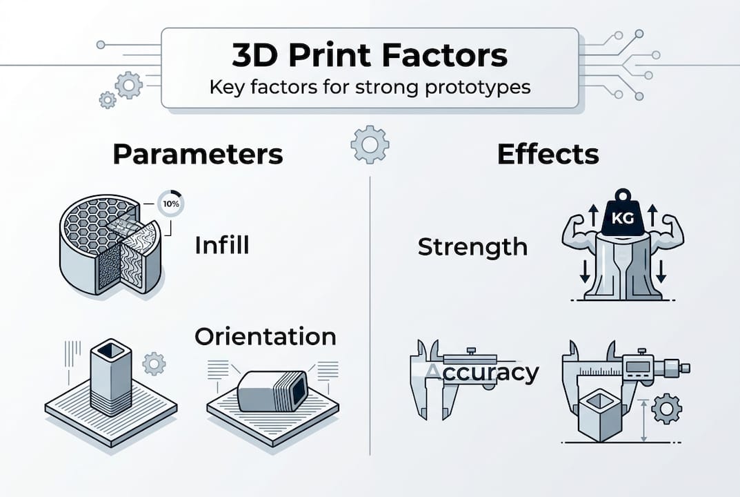
The parameters that matter most:
| Parameter | Effect on prototype | Recommended range |
|---|---|---|
| Infill density | Drives tensile, compression, and impact strength | 20% to 60% for most functional parts |
| Layer height | Controls surface roughness and Z-axis detail | 0.1 mm to 0.3 mm |
| Wall thickness | Determines shell rigidity and surface finish | Minimum 1.2 mm for structural parts |
| Print orientation | Governs anisotropic strength distribution | Orient load-bearing axis away from Z |
Infill density impacts tensile strength by 55%, compression strength by 81%, and impact strength by 64% in PLA. That is not a marginal difference — going from 20% to 60% infill is an engineering decision, not a print setting.
Infill pattern also matters more than most teams realize. Gyroid infill boosts bending modulus 15 to 35% compared to honeycomb, making it the better choice for parts that will experience lateral load. Layer thickness affects both surface roughness and hardness. And Z-axis strength remains anisotropic — parts printed vertically are significantly weaker along their build direction than parts printed flat.
Common design mistakes that create problems:
- Thin walls below 0.8 mm: The slicer may not generate any toolpath at all, leaving structural voids
- Overhangs steeper than 45 degrees: Without support structures, these collapse during printing
- Tolerances tighter than 0.2 mm: Material shrinkage and thermal expansion make sub-0.2 mm tolerances unreliable in FDM printing
- Ignoring warping on large flat bases: Parts with large footprints need brim settings or material choices that resist bed separation
The good news is that all of these are preventable at the design stage. Resources on designing reliable prototypes and low-volume manufacturing tips give you specific geometry guidelines that catch these issues before manufacturing begins.
Design pitfalls and advanced solutions: Getting print-ready for custom parts
Even with the right technical setup, custom part designs can present tough edge cases. Here is how to address and solve them for a successful print.
The most common problem categories and their solutions:
- Non-manifold geometry: Surfaces that share an edge or overlap internally confuse slicers. Fix with Meshmixer’s Inspector tool or Netfabb’s automatic repair. Always verify with a manifold check before export.
- Thin walls and fragile features: Features below 1.2 mm wall thickness may not print cleanly. Add material to thin features or redesign with a minimum feature size that matches your nozzle diameter.
- Sharp overhangs above 45 degrees: Add chamfers or fillets at transition points. A 1 mm to 2 mm fillet at a sharp edge reduces the overhang angle and eliminates the need for support material in most cases.
- Shrinkage and warping on large parts: Choose materials with lower thermal expansion (like PETG over ABS for moderate-temperature applications) and include a brim in your slicer settings for large flat footprints.
- Over-tight assembly tolerances: Design-in clearance gaps of at least 0.2 mm to 0.3 mm between mating parts. Test fit with a single-layer print of the mating interface before committing to the full print.
- Draft angle omission: Parts designed for injection molding often lack draft angles, which causes adhesion problems on vertical walls during FDM printing. Add 1 to 2 degree draft angles to vertical faces wherever possible.
Non-manifold geometry, thin walls, sharp overhangs, and over-tight tolerances are the leading causes of print failure for custom parts. The fix in almost every case starts with catching the error in the file, not on the printer.
Pro Tip: Before submitting a complex prototype for full production, run a scaled-down test print at 50% size. This validates the geometry, support structures, and layer adhesion in a fraction of the time and material cost of a full-size print.
For unfamiliar geometry types or advanced material requirements, 3D printing jargon defined is a practical reference that clears up terminology confusion between design teams and print specialists. For parts that need to meet strict functional standards, exploring engineering-grade printing options ensures the material and process match the application.
Our perspective: Why mastering 3D art design means thinking beyond the model
Here is what most businesses and product teams miss when approaching 3D art design: a beautiful model is not a manufacturable product. We see it consistently — teams invest heavily in high-end rendering and visual design, then submit a file that fails the first slicer check because no one validated it against print constraints.
The uncomfortable truth is that 3D art design for prototyping requires three disciplines to work together: artistic judgment, engineering precision, and manufacturing awareness. Drop any one of them and your output quality drops. A stunning geometry that ignores layer adhesion mechanics will break under functional load. An accurate CAD file that ignores aesthetics produces a prototype nobody wants to show to stakeholders.
What separates successful teams is iterative, test-driven thinking. They design for the print process, not around it. They run test prints, measure results against specifications, and feed that data back into the next design revision. That loop — design, print, measure, revise — is where real innovation happens. Browsing best 3D print jobs gives you a reference point for what that discipline produces in practice.
How CC3DLabs can turn your design vision into reality
Ready to put world-class 3D art design to work for your business? At CC 3D Labs, we work with product developers and businesses near Philadelphia and across the country to transform high-quality 3D art designs into precise, functional prototypes and custom parts.

Our team handles everything from CAD validation and mesh repair to full-run production using advanced filament-based printing. Whether you need a single concept prototype or a batch of functional parts, our 3D printing services are built for accuracy and fast turnaround. Not sure what your design can produce? Explore what you can print to see the range of applications we support, or jump straight into print on demand to get your project moving with a free online estimate.
Frequently asked questions
What is the difference between 3D art design and regular 3D modeling?
3D art design combines artistic and engineering principles to produce geometry that is both visually resolved and manufacturable, while standard 3D modeling often targets digital-only assets without accounting for physical production constraints. 3D art design translates creative concepts directly into files ready for custom manufacturing.
Why do AI tools for 3D art design need CAD repair before printing?
AI-generated meshes commonly contain non-manifold geometry, surface gaps, and inverted normals that cause slicer failures. CAD repair tools rebuild the mesh structure to make the model watertight and dimensionally accurate. AI tools accelerate ideation but consistently require post-processing before any file is print-ready.
Which technical factor most affects the strength of 3D printed prototypes?
Infill density and print orientation have the greatest combined impact on prototype strength. Infill density impacts tensile strength by 55%, compression by 81%, and impact resistance by 64% in PLA, making it the single highest-leverage parameter in the slicer settings.
What common design pitfalls can ruin 3D print quality?
Thin walls below 0.8 mm, non-manifold geometry, overhangs above 45 degrees, and assembly tolerances tighter than 0.2 mm are the most frequent causes of failed or unusable prints. Non-manifold geometry, thin walls, and over-tight tolerances can all be caught and corrected during the design validation stage before manufacturing begins.