
TL;DR:
- 3D scanning provides precise digital models, faster prototyping, and reliable quality control.
- Choosing the right technology depends on accuracy, object size, surface, and budget.
- Integrating 3D scanning early improves design accuracy, reduces errors, and accelerates workflows.
3D scanning gets dismissed as a glorified copy machine for 3D printing. That misunderstanding costs product teams weeks of rework and thousands in avoidable errors. In reality, 3D scanning is one of the most powerful tools available for businesses that need precise digital models, faster prototyping cycles, and reliable quality control. This guide walks you through how 3D scanning works, the main technologies available, the real business benefits, and how to integrate scan data into your design and manufacturing workflows without the common pitfalls.
Table of Contents
- How 3D scanning works: The basics explained
- Main types of 3D scanning technologies compared
- Key benefits for product development and manufacturing
- From scan to workflow: Where and how 3D data is used
- Common challenges and tips for getting reliable 3D scans
- Our take: Why mastering 3D scanning drives real innovation
- Level up your workflow with CC3DLabs 3D scanning and printing solutions
- Frequently asked questions
Key Takeaways
| Point | Details |
|---|---|
| 3D scanning basics | 3D scanning transforms real objects into accurate digital models for design and prototyping. |
| Top technologies | Laser triangulation, structured light, and photogrammetry each suit different accuracy and use-case needs. |
| Business benefits | 3D scanning saves time, reduces errors, and enables rapid iteration in product development and manufacturing. |
| Workflow integration | Scanned data seamlessly fits into CAD and production pipelines, connecting design with manufacturing. |
| Real-world success tips | Preparation, surface treatment, and calibration improve scan quality and project success. |
How 3D scanning works: The basics explained
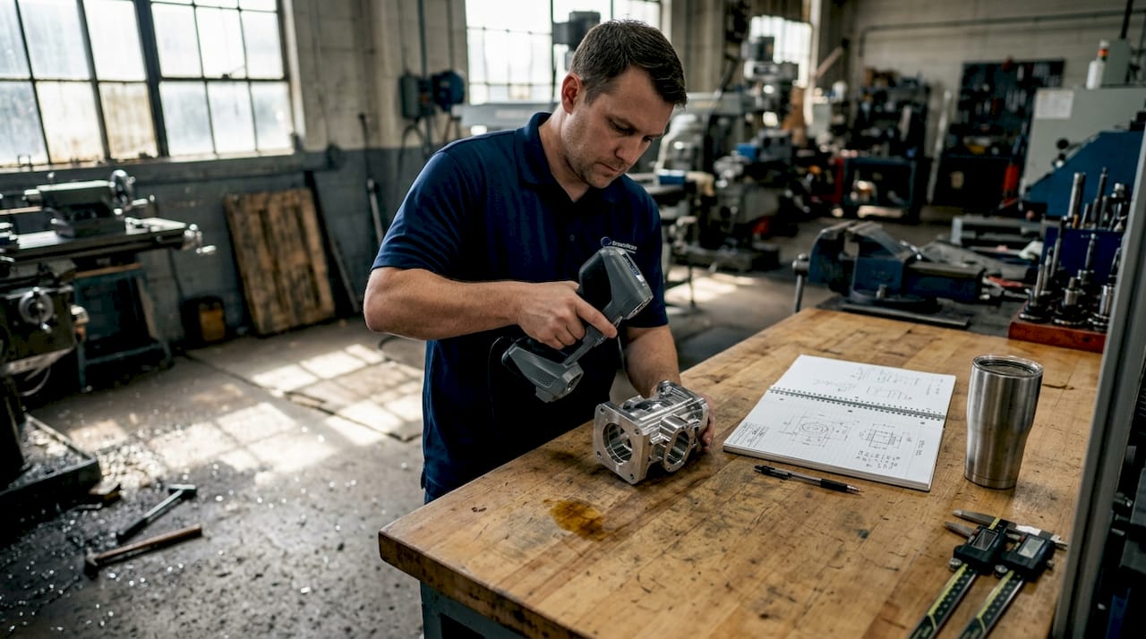
At its core, 3D scanning captures the exact geometry and surface details of a physical object and converts that data into a digital model. That model can then be edited, analyzed, reproduced, or fed directly into a CAD (computer-aided design) system. The process has three main stages: data capture, point cloud creation, and mesh or model generation.
During data capture, the scanner emits light, laser beams, or uses cameras to measure the surface of an object from multiple angles. Each measurement records the position of a point in 3D space. Thousands or even millions of these points combine to form a point cloud, which is essentially a dense map of the object’s surface geometry. That point cloud is then processed into a mesh, a connected surface made of triangles, which becomes the usable 3D model.
The three most common scanning technologies are:
- Laser triangulation: Projects a laser line or point onto the surface; a sensor reads the reflected angle to calculate position. Laser triangulation is highly accurate for short-range work and fine detail.
- Structured light: Projects a pattern of light (often stripes) onto the object and uses cameras to measure how the pattern deforms across the surface. Fast and excellent for medium-sized parts.
- Photogrammetry: Uses overlapping photographs taken from different angles to reconstruct a 3D model mathematically. Cost-effective and scalable for larger objects.
Learning how 3D scanning optimizes workflows early in a project helps teams avoid costly design revisions later.
Pro Tip: Lighting and object positioning matter more than most people expect. Consistent, diffused lighting reduces shadows and surface noise, which directly improves point cloud density and model accuracy.
A poorly set up scan environment can introduce errors that ripple through every downstream step, from CAD modeling to final part inspection. Investing 15 minutes in proper setup saves hours of cleanup.
Main types of 3D scanning technologies compared
Now that you know the basics, let’s compare the main 3D scanning techniques so you can match the right tool to your project.
Choosing the wrong scanning method is one of the most common mistakes product teams make. Each technology has a distinct performance profile depending on accuracy needs, object size, surface type, and budget.
| Technology | Accuracy | Speed | Cost | Best for |
|---|---|---|---|---|
| Laser triangulation | Very high | Moderate | Medium-high | Small parts, fine detail |
| Structured light | High | Fast | Medium | Mid-size parts, smooth surfaces |
| Photogrammetry | Moderate | Slow | Low | Large objects, outdoor use |
| CT scanning | Extremely high | Slow | Very high | Internal geometry, medical |
Here is a simple process for matching your scanning method to your application:
- Define your accuracy requirement. Engineering tolerances under 0.05mm demand laser triangulation or CT scanning.
- Assess your object size. Larger objects favor photogrammetry or structured light; small precision parts favor laser-based methods.
- Evaluate the surface. Reflective or dark surfaces need special preparation regardless of technology.
- Set your budget. Photogrammetry is the most accessible entry point; CT scanning is reserved for high-value inspection needs.
- Consider turnaround time. Structured light scanning is typically the fastest for medium-complexity parts.
Understanding the key 3D scanning techniques available helps you ask better questions when working with a scanning service provider.
Pro Tip: For highly detailed engineering parts or small components, laser triangulation consistently delivers the best results. It is the standard choice for metrology-grade work where tolerances are tight and repeatability is critical.
Key benefits for product development and manufacturing
With the options in mind, let’s look at the real business benefits of integrating 3D scanning into your development process.
The most immediate gain is the elimination of manual measurement. Traditional calipers and coordinate measuring machines (CMMs) are slow, operator-dependent, and limited in the complexity of geometry they can capture. 3D scanning captures the full surface of a part in minutes, with far less human error involved.
| Workflow factor | Traditional method | 3D scanning method |
|---|---|---|
| Measurement time (medium part) | 2 to 4 hours | 15 to 45 minutes |
| Error rate | Higher (operator-dependent) | Significantly lower |
| Geometry complexity handled | Limited | Full freeform surfaces |
| Iteration speed | Slow | Fast |
| Documentation quality | Manual records | Full digital archive |
The real-world impact spans multiple business functions:
- Part design: Capture existing components with no original CAD file and rebuild them accurately.
- Reverse engineering: 3D scanning significantly increases accuracy in reverse engineering and prototyping, reducing guesswork entirely.
- Quality control: Compare scanned production parts against the original CAD model to catch deviations before they become costly defects.
- Tooling verification: Confirm that molds and fixtures match design intent before committing to full production runs.
Teams focused on ensuring 3D scan quality for manufacturing report faster iteration cycles and fewer engineering change orders. For businesses doing reverse engineering with 3D scanning, the ability to digitize legacy parts without original drawings is a significant competitive advantage.
The compounding effect is real. Fewer errors early in development mean fewer corrections late, which directly reduces cost per prototype and shortens time to market.
From scan to workflow: Where and how 3D data is used
Understanding the benefits, let’s explore where 3D scan data delivers real impact in business workflows.
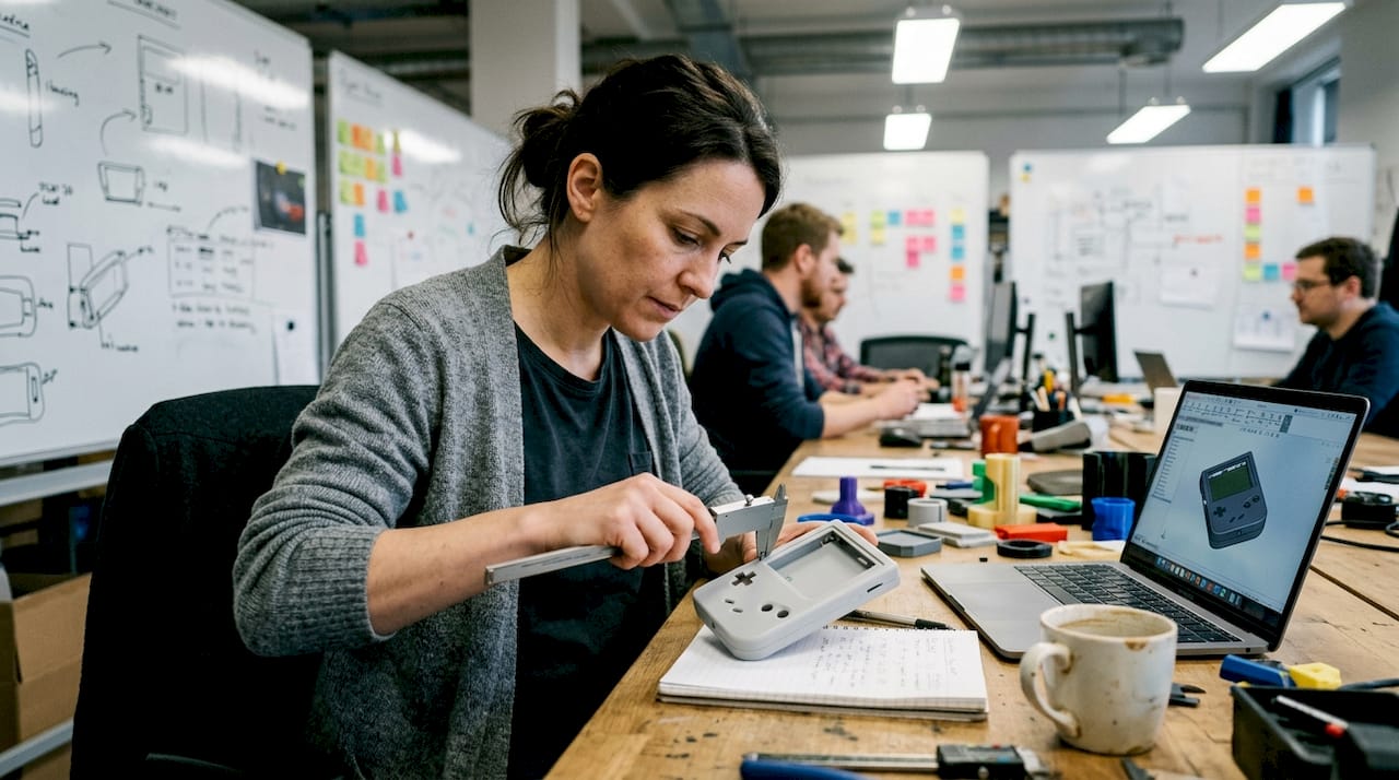
A raw point cloud is useful, but its true value comes when it is converted into a workable CAD model. Most professional scanning workflows use software like Geomagic, Artec Studio, or SOLIDWORKS to process the point cloud into a clean mesh, then into a parametric CAD file that designers can modify and manufacture from.
Here are the most common ways businesses use 3D scan data:
- Reverse engineering: Recreate parts with no existing drawings, especially for legacy components or competitor benchmarking.
- Quality inspection: Overlay the scan against the original CAD model to produce a color deviation map showing where parts are out of tolerance.
- Tooling and fixture verification: Confirm that production tooling matches design specifications before first-article inspection.
- Archiving: Build a permanent digital record of physical assets, molds, or prototypes for future reference.
- Design iteration: Scan a physical prototype, bring it into CAD, refine it, and print or machine the next version faster.
“Modern 3D scanning streamlines the full development pipeline for new and legacy products, reducing the gap between physical reality and digital design intent.”
Exploring 3D scanning in CAD workflows shows just how tightly scanning integrates with modern design tools. Teams that understand using 3D scan data in CAD can move from physical object to production-ready file in a fraction of the time traditional methods require.
The key insight is timing. Scanning should not be an afterthought reserved for inspection. Integrating it early, at the concept and first-prototype stage, is where the biggest gains in speed and accuracy happen.
Common challenges and tips for getting reliable 3D scans
To wrap up the core guide, let’s address the most common snags and how smart teams get reliable results consistently.
Even with good equipment, scan quality can suffer if preparation and technique are not right. Surface type and environment directly influence scan accuracy, and skipping preparation steps is the fastest way to produce unusable data.
The most common challenges and how to address them:
- Reflective surfaces: Shiny metals and plastics scatter laser or structured light unpredictably. Apply a temporary matte scanning spray to create a uniform, readable surface.
- Dark or black surfaces: These absorb light rather than reflecting it, creating data gaps. Scanning spray also solves this problem in most cases.
- Object movement: Even small vibrations during a scan introduce misalignment. Use a stable fixture or turntable to hold the part securely.
- File misalignment: When combining multiple scan passes, poor alignment creates visible seams in the mesh. Use reference markers (small adhesive targets) placed on the object before scanning to give the software fixed registration points.
- Calibration drift: Scanners can drift out of calibration over time or with temperature changes. Always run a calibration check before a critical scan session.
Pro Tip: For complex objects that require multiple scan passes, place reference markers on the object before you start. These give the alignment software fixed anchor points, which dramatically reduces mesh errors and cleanup time afterward.
Visit our tips for high quality 3D scanning resource for a deeper breakdown of preparation and post-processing best practices. Proper technique at the scan stage protects every hour of CAD work that follows.
Our take: Why mastering 3D scanning drives real innovation
Most conversations about 3D scanning focus on speed and cost savings. Those are real, but they are not the most important part of the story.
What we see consistently at CC 3D Labs is that businesses which integrate scanning early in their process do not just move faster. They think differently. When your team can digitize any physical object in minutes and bring it into a shared CAD environment, the collaboration between designers, engineers, and production teams changes fundamentally. Decisions get made with real geometry, not assumptions.
The conventional wisdom treats scanning as a QC or reverse engineering tool used after design is mostly done. That is backwards. The teams that leapfrog competitors use real-world 3D scanning insights to inform design from the very first prototype. They catch fit and function issues in the digital model before a single part is machined or molded.
The future of product development is agile, and agility requires closing the loop between physical and digital as fast as possible. 3D scanning is the bridge. Mastering it is not a technical upgrade. It is a strategic one.
Level up your workflow with CC3DLabs 3D scanning and printing solutions
Ready to put these insights into action for your business?

CC 3D Labs offers metrology-grade 3D scanning services paired with end-to-end CAD modeling and pro-level 3D printing for product developers and manufacturers near Philadelphia and beyond. Whether you need to digitize a legacy part, verify a production run, or accelerate your prototyping cycle, our team handles the full workflow from scan to finished part. Browse our CAD project gallery to see real examples of scan-to-print projects, or request a free estimate to get started on your next build.
Frequently asked questions
What is 3D scanning used for in business?
Businesses use 3D scanning for design accuracy, prototyping, reverse engineering, and quality control. It significantly increases accuracy in reverse engineering and prototyping compared to manual measurement methods.
Which 3D scanning method is best for fine detail?
Laser triangulation is best for short-range, high-precision applications and is the standard choice for capturing highly detailed or small parts at engineering tolerances.
What impacts 3D scanning accuracy?
Surface reflectivity, ambient lighting, and scanner calibration are the three biggest factors. Surface type and environment require careful preparation to achieve reliable, repeatable scan results.
Can 3D scan data be edited or modified?
Yes. Scan data is processed into a mesh and then converted to a parametric CAD model, which designers can fully edit, refine, and adapt for manufacturing or further prototyping.