
TL;DR:
- A modern CAD workflow in 2026 relies on disciplined parametric modeling, PLM-enforced version control, and 3MF exports to produce print-ready parts efficiently. Consistently sequencing assembly, validation, and detail features prevents costly rework and ensures reliable manufacturing outcomes. Process discipline, rather than software upgrades, remains the key to optimizing design and production efficiency.
A modern CAD modeling workflow is a structured sequence of design operations that, when executed correctly, reduces iteration time and produces print-ready geometry with fewer errors. For product developers and engineers targeting 3D printing efficiency in 2026, the difference between a functional workflow and a chaotic one comes down to three disciplines: parametric modeling in tools like SOLIDWORKS or CATIA, data management through PDM/PLM systems, and export practices built around the 3MF file format. Get those three right, and every downstream step from CAE validation to physical print becomes faster and more predictable.
What are the essential tools for a CAD modeling workflow in 2026?
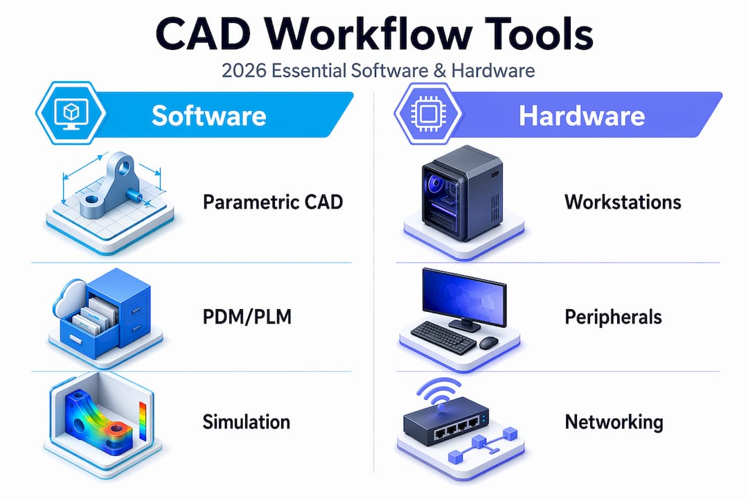
The foundation of any efficient CAD design process in 2026 is software that supports parametric, feature-based modeling. SOLIDWORKS, CATIA, and Solid Edge are the three platforms most widely used in professional product development because each supports full constraint-driven geometry, assembly management, and direct integration with simulation and manufacturing tools. Choosing between them depends on industry context: CATIA dominates aerospace and automotive, SOLIDWORKS leads in mechanical product design, and Solid Edge offers strong sheet metal and frame capabilities.

Hardware matters more than most engineers admit. Complex assemblies with hundreds of components demand workstations with high single-core clock speeds, 32–64 GB of RAM depending on assembly size, and certified graphics cards from NVIDIA Quadro or AMD Radeon Pro lines. Running a 400-part assembly on an underpowered machine does not just slow you down. It introduces instability that corrupts rebuild sequences and forces manual intervention.
PDM/PLM systems replace shared folders as the backbone of file management. They enforce check-in/check-out protocols, maintain full version history, and apply naming conventions automatically. Without them, teams routinely work on outdated geometry and produce conflicting revisions that cost days to reconcile.
| Tool category | Recommended options | Primary benefit |
|---|---|---|
| Parametric CAD | SOLIDWORKS, CATIA, Solid Edge | Constraint-driven design and assembly management |
| PDM/PLM | SOLIDWORKS PDM, Windchill, Teamcenter | Version control and change management |
| Simulation (CAE) | ANSYS, Abaqus, SOLIDWORKS Simulation | Structural, thermal, and fluid validation |
| Slicing/export | PrusaSlicer, Bambu Studio, Chitubox | 3MF and G-code generation for printing |
Pro Tip: Keyboard shortcuts and templates can improve productivity by 20 to 30% in professional CAD environments. Build a custom startup template with your standard units, material libraries, and drawing formats before starting any new project.
How to structure your CAD workflow steps for 3D printing projects
A well-structured CAD workflow follows a deliberate sequence. Skipping steps or reordering operations to save time upfront almost always creates larger problems during validation and export. The following sequence applies to parametric solid modeling for additive manufacturing projects.
-
Define the assembly structure first. Before modeling a single part, map out the functional subassemblies. Identify which components move, which are fixed, and where the critical interfaces are. This prevents structural rework later when parts fail to mate correctly.
-
Create master sketches to drive parametric design. A master sketch is a 2D layout sketch at the assembly level that defines key dimensions, reference planes, and spatial relationships. Changes to the master sketch propagate through all dependent parts automatically, which is the core advantage of parametric modeling.
-
Model base volumes before adding detail features. Build the primary solid geometry first: extrusions, revolves, and lofts that define the overall shape. Leave fillets, chamfers, threads, and surface textures for later. Applying fillets too early creates large rebuild penalties and should be postponed until base volumes are fully validated.
-
Validate geometry before detailing. Run interference checks and confirm wall thicknesses meet your printer’s minimum requirements before adding any cosmetic or functional detail features. Catching a wall thickness violation at this stage takes minutes. Catching it after threading and filleting takes hours.
-
Add detail features in a controlled sequence. Apply threads, fillets, chamfers, and surface finishes only after base geometry passes validation. Group similar operations together to minimize rebuild cycles.
-
Embed review steps throughout, not just at the end. Formal review steps embedded throughout the process reduce rework iterations and drawing errors significantly. Schedule a peer review after step 3 and again after step 5.
Pro Tip: For complex assemblies, use a top-down modeling approach where the master sketch lives at the assembly level. For simpler parts, bottom-up modeling is faster and easier to manage.
| Workflow approach | Best for | Key trade-off |
|---|---|---|
| Top-down (master sketch driven) | Complex multi-part assemblies | Higher setup time, lower rework risk |
| Bottom-up (independent parts) | Simple parts and small assemblies | Faster start, harder to propagate global changes |
| Hybrid | Mid-complexity products with modular subassemblies | Balances speed and control |
How does CAD integrate with CAM, CAE, and PLM for manufacturing?
CAD is the source of truth for geometry and tolerances. Every downstream system, whether it is a simulation solver or a CNC toolpath generator, reads from the CAD model. That dependency makes the quality of the CAD model the single largest variable in manufacturing outcome. CAD-CAM-CAE integration through PLM coordination ensures that only validated designs proceed to production.
The integration loop works as follows:
- CAD defines geometry, tolerances, and material specifications.
- CAE (tools like ANSYS or SOLIDWORKS Simulation) validates structural, thermal, and fluid performance against design requirements.
- CAM (tools like Mastercam or Fusion 360 CAM) generates toolpaths and manufacturing instructions from validated CAD geometry.
- PLM (Windchill, Teamcenter, or SOLIDWORKS PDM) coordinates the gating between each phase, controls who can approve transitions, and triggers re-validation when edits occur after approval.
The gating function of PLM is what most teams underuse. Without formal gates, engineers edit geometry post-CAE without triggering a new simulation run. That gap between the validated model and the manufactured model is where costly field failures originate. Every geometry change after CAE sign-off must restart the validation cycle. PLM enforces that rule automatically when configured correctly.
| Phase | Primary tool | Output |
|---|---|---|
| Geometry definition | SOLIDWORKS, CATIA | Parametric solid model with tolerances |
| Performance validation | ANSYS, Abaqus | Simulation report and pass/fail status |
| Manufacturing prep | Mastercam, Fusion 360 CAM | Toolpaths, G-code, or print instructions |
| Change control | Windchill, Teamcenter | Approved revision with audit trail |
What file formats optimize CAD models for 3D printing?
3MF is the preferred format for additive manufacturing in 2026. Unlike STL, which stores only surface triangles with no color, material, or metadata, 3MF packages geometry, slicer settings, color assignments, material specifications, and project information inside a single ZIP/XML container. That means a 3MF file sent to a printer or service bureau carries everything needed to reproduce the design intent without a separate specification document.
STL remains common because legacy workflows depend on it, but its limitations create real problems. STL files carry no unit information, no material data, and no tolerance context. A print service receiving only an STL file must make assumptions about scale, orientation, and material that the designer never intended. Those assumptions cause the “mysterious” print failures that engineers spend hours diagnosing.
The right export package for any serious 3D printing project includes three files. First, the 3MF for the printer or service bureau. Second, a STEP file for cross-software review and manufacturing quotes, since STEP preserves solid geometry and works across all major CAD platforms. Third, a 2D drawing with GD&T callouts that documents tolerances, critical surfaces, and inspection requirements.
Pro Tip: Before exporting, run a mesh quality check inside your CAD tool or a dedicated utility like Netfabb or Meshmixer. Look for non-manifold edges, inverted normals, and gaps in the mesh. These defects are invisible in the CAD environment but cause slicer failures that are hard to trace back to their source. Learn more about optimizing CAD file formats for additive manufacturing.
What common mistakes slow down CAD modeling efficiency?
The most expensive mistake in parametric CAD is applying heavy operations too early. Moving fillets and threads to the end of the feature tree is not just a style preference. Reversing detail and main shape operations causes considerable time loss. For complex models with 400 or more cavities, restructuring the feature order has reduced computation time from over an hour to seconds.
Version control failures are the second most common source of rework. Engineers working from shared folders without PDM often edit the wrong revision, overwrite a colleague’s changes, or submit geometry that was superseded two days earlier. Strong data management practices like templates, naming conventions, and version control underpin sustainable workflow efficiency. There is no software feature that compensates for absent version discipline.
GD&T errors are subtler but equally damaging. Tolerance attachments and derived datum controls are often not automatically validated by CAD constraint solvers, which means incorrect or missing GD&T semantic attachments require engineering review even in automated workflows. Choosing between ISO 1101 and ASME Y14.5 is not a minor formatting decision. It directly affects inspection outcomes and manufacturing conformance, particularly for aerospace and medical applications.
- Apply fillets, chamfers, and threads only after base geometry validation passes.
- Use PDM check-in/check-out for every file, even on solo projects.
- Verify GD&T callouts against the applicable standard (ISO 1101 or ASME Y14.5) before releasing drawings.
- Run interference analysis at the assembly level before detailing individual parts.
- Automate repetitive exports with macros to eliminate manual errors and save time.
“Most CAD workflow efficiency gains come from disciplined process improvements rather than solely new software features.” — Efficient modeling workflow guide
Key takeaways
An optimized CAD modeling workflow in 2026 requires parametric discipline, PLM-enforced version control, and 3MF-based exports to produce reliable, print-ready geometry at speed.
| Point | Details |
|---|---|
| Structure before modeling | Define assembly hierarchy and master sketches before creating any part geometry. |
| Delay detail features | Apply fillets, threads, and chamfers only after base volumes pass interference checks. |
| Use PDM/PLM for all files | Version control through Windchill or SOLIDWORKS PDM prevents costly revision conflicts. |
| Export 3MF plus STEP | Send 3MF for printing and STEP with 2D drawings for manufacturing quotes and review. |
| Gate every phase | PLM must trigger re-validation after any geometry edit post-CAE approval. |
Why process discipline beats software upgrades every time
I have watched teams spend significant budget on new CAD seats and simulation licenses, then wonder why their iteration cycles did not shorten. The answer is almost always the same. The software was not the bottleneck. The process was.
The most impactful change I have seen in any CAD environment was not a software upgrade. It was a team that committed to top-down assembly structuring and master sketch discipline. Their rebuild times dropped from hours to minutes on assemblies that had previously been nightmares to modify. The tools were the same. The sequence changed.
What I tell every product developer I work with is this: map your current workflow on paper before touching any settings. Identify where you are applying operations out of order, where files live outside PDM, and where GD&T callouts are being added as afterthoughts. Those three areas account for the majority of rework in most teams I have seen.
The future CAD workflows that will define 2026 and beyond are not defined by AI-assisted sketching or cloud rendering. They are defined by teams that treat their modeling sequence as a living process, review it regularly, and enforce it consistently. Technology amplifies discipline. It does not replace it.
— Justin
How Cc3dlabs supports your CAD-to-print workflow
When your CAD model is ready for production, the transition from file to physical part should be frictionless. Cc3dlabs specializes in handling complex CAD files optimized for additive manufacturing, accepting 3MF, STEP, and native formats to preserve your design intent from model to print.

Whether you need a single functional prototype or a batch of production parts, Cc3dlabs’ professional 3D printing services near Philadelphia cover multi-color printing, professional handheld 3D scanning (accuracy to ~0.1 mm), and design support for engineers who need accurate, durable results fast. If you want to see how 3D printing drives product innovation in 2026, the Cc3dlabs team is ready to take your optimized CAD files and turn them into parts that perform.
FAQ
What is a CAD modeling workflow?
A CAD modeling workflow is a structured sequence of design steps that takes a product from concept geometry to a validated, export-ready model. It includes assembly structuring, parametric modeling, simulation validation, and file export for manufacturing or 3D printing.
What is the best CAD software for 3D printing in 2026?
SOLIDWORKS and Fusion 360 are the most widely used platforms for 3D printing-focused design because both support parametric modeling and direct 3MF export. CATIA and Solid Edge are preferred in aerospace and automotive contexts where tighter PLM integration is required.
Why is 3MF better than STL for 3D printing?
3MF stores geometry alongside colors, materials, slicer settings, and project metadata inside a single ZIP/XML package, while STL stores only surface triangles with no unit or material information. That metadata gap in STL files causes scale errors and print failures that 3MF eliminates by design.
How does PLM improve CAD workflow efficiency?
PLM systems like Windchill and Teamcenter gate each design phase, enforce re-validation after geometry edits, and maintain a full audit trail of approved revisions. Without PLM, teams routinely manufacture from outdated or unapproved geometry, which is the leading cause of costly production rework.
When should you apply fillets and chamfers in a CAD model?
Apply fillets, chamfers, and threads only after base geometry has passed interference checks and wall thickness validation. Adding detail features too early creates rebuild penalties that can extend computation time from seconds to over an hour on complex assemblies.